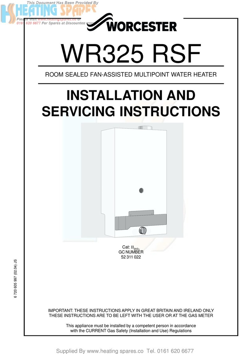
1.1 as Safety (Installation and Use) Regulations 1984:- All gas
appliances must be installed by a competent person in
accordance with the above regulations. Failure to install
appliances correctly could lead to prosecution.
1.2 The manufacturer’s notes must not be taken, in any way, as
overriding statutory obligations.
1.3 The compliance with a British Standard does not, of itself,
confer immunity from legal obligations. In particular the
installation of this appliance must be in accordance with the
relevant requirements of the as Safety (Installation and Use)
Regulations 1984 (as amended), local Building Regulations, Building
Standards (Scotland) (Consolidation), byelaws of the local Water
Company and Health and Safety Document No. 635 (Electricity at
Work Regulations 1989). It should be in accordance with the
relevant recommendations of the following British Standards.
BS 6798:1987 Specification for Installation of gas fired hot water
boilers of rated input not exceeding 60 kW.
BS 5546:1990 Installation of gas hot water supplies for domestic
purposes.
BS 5440:1:1990 Flues and ventilation for gas appliances of rated
input not exceeding 60 kW: Flues.
BS 5440:2:1989 Flues and ventilation for gas appliances of rated
input not exceeding 60 kW: Air Supply.
BS 6891:1988 Installation of low pressure gas pipework
installations up to 28 mm (R1).
1. To ensure that the installation will perform to the highest
standards, the system and components should conform to any
other relevant British Standards in addition to those mentioned
in the instructions.
2.1 This appliance is available for use with natural gas.
When installing the appliance for use with natural gas, please
check 10 digit number on carton to ensure that the correct
appliance has been specified. The 10 digit number for a natural
gas appliance is 7 702 340 006.
2.2 This appliance is available for use with LP .
When installing the appliance for use with LP , please check 10
digit number on carton to ensure that the correct appliance has
been specified.
The 10 digit number for an LP appliance is 7 702 440 007.
2.3 This appliance is not suitable for external installation.
2. The appliance is set to provide a maximum output of 21.4
kW and a minimum output of 7 kW.
2.5 The appliance has a permanent pilot.
2. General Information
1. Installation Regulations
1. Installation Regulations.................................................Page 2
2. eneral Information ......................................................Page 2
3. Technical Data ................................................................Page 5
4. Siting the Appliance ......................................................Page 5
3. Siting the Flue Terminal ........................ ........................Page 5
6. Air Supply .......................................................................Page 6
7. as Supply ..................................... ................................Page 6
8. Installation ................ .....................................................Page 6
9. Commissioning ..............................................................Page 7
10. Inspection and Servicing ..............................................Page 8
11. Replacement of Parts ....................................................Page 9
12. Fault Finding ....................... ...........................................Page 10
13. Short Parts List ...................... ........................................Page 10
2.6 PRINCIPLE APPLIANCE COMPONENTS
A low thermal capacity as to Water heat exchanger.
A stainless steel main gas burner.
A gas section.
A water section.
A thermoelectric safety valve.
2.7 PACKING
The appliance and flue components are packed in separate
cartons.
2.8 GENERAL INSTALLATION
If the appliance is to be fitted into a compartment, the
compartment must conform to the requirements of BS
6798:1987: Section 6.
The specified ventilation openings made into a wall or
compartment door must not be obstructed.
Do not place anything on top of the appliance.
The clearances specified for servicing must be maintained.
2.9 FLUE
The appliance has a room-sealed balanced flue system to the
rear.
The standard flue assembly will accommodate a wall thickness
of between 260 mm and 430 mm. The 10 digit code number for
the standard flue assembly is 7 709 000 423.
A short flue assembly is available and will accommodate a wall
thickness of between 100 mm and 150 mm. The 10 digit code
number for the short flue assembly is 7 709 000 425.
An extended flue assembly is available and will accommodate a
wall thickness of between 410 mm and 570 mm. The 10 digit
code number for the extended flue assembly is 7 709 000 424.
2.10 FACILITY TO FIT A SPOUT AND INTEGRAL TAP KIT
The appliance has the facility for a spout and integral tap kit to
be fitted for oversink installation. If this type of installation is
required, please order the following components as necessary:
Integral tap kit
(incorporating hot and cold taps and handles) 7 709 000 406
Chrome plated swivel spout – 150 mm length 7 709 000 041
Chrome plated swivel spout – 250 mm length 7 709 000 042
Chrome plated swivel spout – 350 mm length 7 709 000 043
2
Contents
