Workhorse Products SUPER SECA User manual

23730 E. SOUTHERN AVE., PHOENIX, AZ 85040 | USA
CONGRATULATIONS!
You are now the proud owner of a Super Seca Flash Curing Unit.
We thank you for choosing Workhorse Products!
While our packaging has been designed to handle normal shipping conditions, we
cannot foresee damages caused by the carrier and are not responsible for damages
that occur during transportation.
Be sure to inspect the crate contents IMMEDIATELY, while the carrier is still present.
If shipping damage has occurred:
1) Contact the carrier to file a claim immediately
2) Contact Workhorse Products at 800.778.8779
---- AND ----
THE IMPORTANCE OF THE OWNER’S MANUAL
The purpose of the Owner’s Manual is to familiarize you with the parts and operations
of the Super Seca. There are step-by-step instructions to assemble the product,
explanations of the product’s key features, and additional information that will help with
the maintenance of the product.

3
800.778.8779 | WORKHORSEPRODUCTS.COM
TABLE OF CONTENTS
SAFETY INFORMATION
SPECIFICATIONS
PARTS FOR ASSEMBLY
ASSEMBLY
STEP 1: Attach legs and insert levelers
STEP 2: Assembling the top plate and inner tube
STEP 3: Installing inner tube and top plate onto heating element
STEP 4: Installing reflector skirts
USING THE SUPER SECA FLASH
ELECTRIC
WIRING DIAGRAM
LIMITED WARRANTY
4
5
6
7
8
9
10
12
13
14
15
I.
II.
III.
I V.
V.
VI.
VII.
VIII.

43730 E. SOUTHERN AVE., PHOENIX, AZ 85040 | USA
SAFETY INFORMATION
WARNING!
RISK OF ELECTRICAL SHOCK! Turn ALL power to the unit OFF before service.
All service should be done by or under the supervision of a trained technician.
THIS ELECTRIC FLASH CURE UNIT IS INTENDED SOLELY FOR THE PURPOSE OF CURING
INK ON TO TEXTILE AND CUT GOODS. THIS FLASH IS NOT INTENDED FOR USE IN
HEATING, CURING OR BAKING OF ANY OTHER MATERIALS WHATSOEVER. THIS FLASH
IS INTENDED FOR IN-DOOR USE ONLY.
THE EXCLAMATION WITHIN AN EQUILATERAL TRIANGLE IS INTENDED TO ALERT THE
USER OF IMPORTANT SAFETY PRECAUTIONS SHOP PERSONNEL SHOULD BE AWARE
OF DURING OPERATION.
For your safety, do not store or use any flammable liquids in the vicinity (within at least 3 feet)
of this appliance
Never place any item other than the stock to be cured or dried under the flash element
Never leave the flash unit unattended when it is operating
Do not perform maintenance on this machine until unit is un-plugged
Never alter the internal wiring of this machine

5
800.778.8779 | WORKHORSEPRODUCTS.COM
SPECIFICATIONS
Part Number
Head Size
Power Requirements
11010-SS-1616-C
16” x 16”
(41cm x 41cm)
ELECTRIC
110V, 50-60Hz, 1600 Watts, 14 amps
11010-SS-1818-C
18” x 18”
(46cm x 46cm)
ELECTRIC
110V, 50-60Hz, 1950 Watts, 17 amps
11010-SS-1818-220-C
18” x 18”
(46cm x 46cm)
ELECTRIC
220V, 50-60Hz, 2500 Watts, 12 amps
11010-SS-1824-C
18” x 24”
(46cm x 61cm)
ELECTRIC
220V, 50-60Hz, 3000 Watts, 14 amps
11010-SS-2424-C
24” x 24”
(61cm x 61cm)
ELECTRIC
220V, 50-60Hz, 4000 Watts, 18 amps
MODEL NUMBER
MODEL NUMBER
SS1616C SS1818C110 SS1818C220
SS1824C SS2424C
Part Number
Head Size
Power Requirements

63730 E. SOUTHERN AVE., PHOENIX, AZ 85040 | USA
PARTS FOR ASSEMBLY
DESCRIPTION
Flash Element (16x16)
Reflective Skirt (16x16)
Legs (16x16)
Inner Tube
Lower Tube
Top Plate
Shaft Collar
Handle Bar
Tapered Knob
Angle Adjustment Knob
Hex Bolt (1/4 20 x 1-1/4)
Lock Washer
Flat Washer
Silver Screw
Leveler
Hex Nut
Mounting Screw
QTY. PART NUMBER
1
3
5
1
1
1
1
1
1
1
12
12
2
9
5
12
8
390617
81524
85923
85291
85292
81496
50-2437
81497
40-1825
56-2050
41-HB-250-58
43-LOK-250-32
43-FLT-250-11
41-HB-250-15
40-1635
42-HEX-250-10
41-PSMS-12-175
The part numbers will
differ depending on the
specific model being
assembled.
In this manual, a 16” x
16” Super Seca Flash is
being assembled.
The part number will
not match if assembling
another model of the
product.

7
800.778.8779 | WORKHORSEPRODUCTS.COM
ASSEMBLY
STEP 1: ATTACH LEGS AND INSERT LEVELERS
TOOLS NEEDED PARTS NEEDED
5 x Legs
10 x Hex Nuts
10 x Lock Washers
10 x Hex Bolts (1/4-20 x1-1/4)
5 x Leg Levelers
Lower Tube
•
•
•
•
•
•
7/16” Ratchet
7/16” Wrench
Line up the holes of the
leg with the holes on the
bottom of the lower tube
and insert two hex bolts.
Using a 7/16” ratchet and
7/16” wrench tighten every
bolt and nut.
On the other side of the
leg thread a lock washer
and a nut onto the
opposite end of each bolt.
Install each leveler an
equal distance from the
bottom of the leg to
ensure base stability.
Repeat steps 1 and 2 for
every leg.
To install the optional
caster system, thread the
caster completely into the
bottom of the leg.
•
•
1.
4.
2.
5.
3.
6.

83730 E. SOUTHERN AVE., PHOENIX, AZ 85040 | USA
ASSEMBLY
STEP 2: ASSEMBLING THE INNER TUBE AND TOP PLATE
TOOLS NEEDED PARTS NEEDED
Inner tube
Top plate
Handle bar
2 x Hex Bolts
2 x Lock Washers
2 x Hex Nut
2 x Flat Washers
•
•
•
•
•
•
•
7/16” Ratchet
7/16” Wrench
Turn the top plate over
along with smaller top
plate piece. Line up the
large hole on both pieces
and stack them.
Screw on a lock washer
and a nut to the other end
of the bolt. Repeat to the
other side. At this point,
both of the bolts should
only be tightened by hand.
Line up the hole on the
bottom of the inner tube
with the hole of the top
plate, and stack the inner
tube on top.
Install the angle
adjustment knob into the
threaded hole on top of
the plate.
Insert and hand tighten a
hex bolt with a flat washer
from the bottom of the
plate, so that the end of
the bolt is exposed on top.
Repeat for the other side.
With a 7/16” ratchet and
7/16” wrench tighten the
two bolts. The inner tube
and top plate are now
assembled.
•
•
1.
4.
2.
5.
3.
6.

9
800.778.8779 | WORKHORSEPRODUCTS.COM
ASSEMBLY
STEP 3: INSTALLING THE INNER TUBE AND TOP PLATE
ONTO HEATING ELEMENT
TOOLS NEEDED PARTS NEEDED
Silver Hex Bolt
Shaft Collar
8 x Mounting Screws
Shaft Collar Wrench
Heating Element
•
•
•
•
•
Phillips Head
Screwdriver
Place the heating element
onto a table. Then stack
the assembled inner tube
and top plate onto the
element, while aligning
the holes.
Place the silver hex bolt under
the top plate into the open
middle hole. The end of the
bolt needs to be exposed on
top. Screw the handle onto
the exposed thread.
Place eight mounting
screws into every hole
except for the very top
middle hole.
Install the shaft collar and
shaft collar wrench onto
the lower tube. Then adjust
the height of the flash
to desired position, and
tighten collar to shaft.
With a Philips screwdriver
tighten the screws slowly.
DO NOT over tighten them.
•
1.
4.
2.
5.
3.

10 3730 E. SOUTHERN AVE., PHOENIX, AZ 85040 | USA
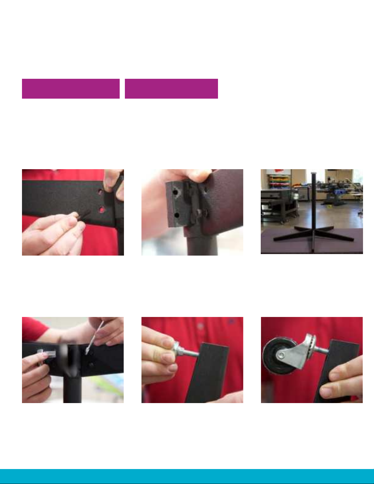
ASSEMBLY
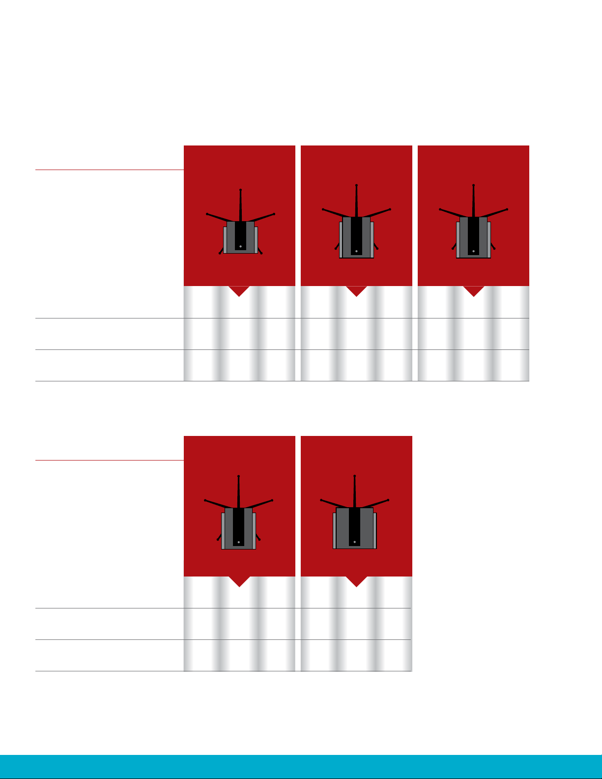
STEP 4: INSTALLING REFLECTOR SKIRTS
TOOLS NEEDED PARTS NEEDED
11 x Screws
3 x Reflector Skirts
•
•
Phillips Head
Screwdriver
Start with the middle
reflective skirt, place
it against the heating
element and align the holes
of the skirt with the holes
of the element.
With the middle skirt and
side skirt attached, thread
the screw at the front
bottom corner.
For the middle skirt, thread
the middle screw first. This
allows for room to adjust if
needed. Thread the other
two screws into the top of
the skirt.
Place the third skirt onto
the other side. Repeat
steps 3 and 4.
Place the second skirt on
either side of the element.
First, thread the screw at the
end in order to leave room
for adjustments. Thread the
other two screws into the
top of the skirt.
•
1.
4.
2.
5.
3.

11
800.778.8779 | WORKHORSEPRODUCTS.COM
CONGRATULATIONS!
Your Super Seca Flash Unit is now fully assembled.

12 3730 E. SOUTHERN AVE., PHOENIX, AZ 85040 | USA
USING THE SUPER SECA FLASH CURE UNIT
The Super Seca Flash Curing Unit is very easy to function.
Place the flash element assembly over the platen. Make sure the placement of the flash does
not make contact with the platen when it rotates.
Once set, swing the element assembly out of the way as to not burn the shirt board when
the unit is turned on. Adjust the height by loosening the shaft collar and holding the element
assembly with one hand to slide the element assembly up or down to the desired height.
Once the position and height are set, plug the unit into a wall receptacle with the correct
voltage for the unit and turn the unit on. The element will take a few moments to reach full
temperature.
When ready to print, swing the element assembly over the platen and begin.
Leveling the base will ensure even heat distribution and an evenly cured print.
Adjusting the flash to an appropriate height will prevent damage to material.
Avoid plugging the Flash Unit into an extension cord. Use a wall receptacle with the correct
voltage.
If the Super Seca won’t heat up, check the power source. If the power source is working fine
and the issue is with the flash, call our Tech Support line for further assistance.
800.778.8779 EXT. 2
1)
2)
3)
4)
•
•
•
•

13
800.778.8779 | WORKHORSEPRODUCTS.COM
ELECTRIC
POWER LOOP/FLASH PLUGS
110V 15amp
NEMA
5-15R
NEMA
6-15R
NEMA
L5-30R
NEMA
L6-30R
NEMA
5-20R
NEMA
6-20R
NEMA
5-15P
NEMA
6-15P
NEMA
L5-30P
NEMA
L6-30P
NEMA
5-20P
NEMA
6-20P
POWER LOOP/FLASH PLUGS
220V 15amp
POWER LOOP/FLASH PLUGS
220V 30amp (old style)
POWER LOOP/FLASH PLUGS
110V 20amp
POWER LOOP/FLASH PLUGS
220V 15amp

14 3730 E. SOUTHERN AVE., PHOENIX, AZ 85040 | USA
WIRING DIAGRAM
Wiring Diagram: 115/220V Element
NOTE: The diagrams for the 115V and 220V models are the same, with variations in the
components only. Shown Below with 220V components: Power Cord, Elements, Light.

15
800.778.8779 | WORKHORSEPRODUCTS.COM
LIMITED WARRANTY
SUPER SECA FLASH CURING UNIT
Although every effort has been made to provide accurate specifications, Workhorse Products does not assume any
liability for damages, whether consequential or incidental, that may result from the use or misuse of the indicated
specifications. Workhorse Products requires the use of a licensed industrial electrician for the installation of
electrical service to equipment requiring electrical power.
Workhorse Products reserves the right to alter specifications in the manufacture of its products. It is understood and
agreed that Seller’s liability for any equipment whether liability in contract, in tort, under any warranty, in negligence,
in strict liability or otherwise shall not exceed the return of the amount of the purchase price paid by Buyer. Not
withstanding the foregoing provision, under no circumstances shall Seller be liable for special, indirect or consequential
damages. The price stated for the equipment is a consideration in limiting Seller’s liability. No action regardless of
form, arising out of the transactions under this Agreement may be brought by Buyer more than five (5) years after
the cause of action has occurred. Our warranty is specified, is exclusive and no other warranty, whether written or
oral, is expressed or implied. Workhorse Products specifically disclaims the implied warranties of merchantability and
fitness for a particular purpose. Equipment manufactured or sold by Workhorse Products is warranted against defects
in workmanship and materials for a period of one year from receipt by customer. All warranties initiate from date of
shipment to original customer. Replacement parts are covered for the term of the equipment warranty period. Parts
not under warranty are covered for thirty (30) days from receipt by customer. Any part found by Workhorse Products to
be defective in material or workmanship within the stated warranty period will be replaced or repaired at Workhorse’s
option without charge.
AFTER OBTAINING AN RMA# SEND RETURNED FREIGHT PREPAID TO:
3730 E. Southern Avenue, PHOENIX, AZ 85040 USA.
Written authorization must be obtained from Workhorse before any part will be accepted. Replacement parts are
sent out freight collect. Parts sent out prior to receiving defective require a credit card hold for cost plus freight.
Upon return of defective part, if it is deemed that the part was not damaged by customer but failed, the cost of the
replacement part will be refunded.
This warranty does not extend to expendable parts such as filters, fuses, elements and brushes, casters. Workhorse
does not warrant failure of parts or components resulting from misuse or lack of proper maintenance. Installation,
inspection, and maintenance costs are the sole responsibility of the purchaser.
FOR WARRANTY TO TAKE PLACE YOU MUST COMPLETE THE PRODUCT REGISTRATION FORM ONLINE:
https://workhorseproducts.com/equipment-registration-form/

WWW.WORKHORSEPRODUCTS.COM
PARTS & SUPPLIES ARE AVAILABLE ONLINE AT:
https://support.workhorseproducts.com/store/
67-1520 REV 0519
Table of contents
Other Workhorse Products Printer manuals