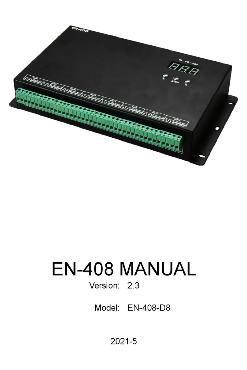
World Uniqueen EN-508 User manual

EN-508 MANUAL
Version:
3.
Model:
EN-508-F10
2021-4

CONTENTS
1. FUNCTION OVERVIEW........................................................................................................................................................1
2. TECHNICAL PARAMETERS...................................................................................................................................................1
3. CONNECTION MODE.......................................................................................................................................................... 2
3.1. PORT INTRODUCTION..................................................................................................................................................2
3.2. CONNECTION DIAGRAM OF CONTROLLER.................................................................................................................. 2
3.3. OPTICAL FIBER COMMUNICATION.............................................................................................................................. 3
3.4. CONNECT WITH LIGHTING FIXTURE............................................................................................................................ 3
3.5. TRANSMISSION DISTANCE........................................................................................................................................... 4
4. BASIC OPERATION.............................................................................................................................................................. 4
4.1. MENU INTRODUCTIION............................................................................................................................................... 4
4.2. PARAMETERS SETTINGS...............................................................................................................................................5
4.2.1. STARTING UP DISPLAY...........................................................................................................................................5
4.2.2. ID SETTINGS.......................................................................................................................................................... 5
4.2.3. IP SETTINGS (ONLY FOR MADRIX SOFTWARE)......................................................................................................5
4.2.4. CONFIGURE ADDRESSING.....................................................................................................................................6
4.2.5. TEST EFFECT.......................................................................................................................................................... 6
4.2.6. CHIP SETTINGS (FOR TEST FUNCTION AND MADRIX SOFTWARE)........................................................................6
4.2.7. CHANNEL OF CHIP (FOR TEST FUNCTION AND MADRIX SOFTWARE).................................................................. 7
4.2.8. BAUD RATE SETTINGS (FOR TEST FUNCTION AND MADRIX SOFTWARE)............................................................. 7
4.2.9. LANGUAGE SETTINGS........................................................................................................................................... 7
4.2.10. RESTORE FACTORY SETTING............................................................................................................................... 8
5. IP ADDRESS SETTINGS (PC)................................................................................................................................................ 8
6. ADDRESSING BY LED PLAYER............................................................................................................................................. 9
7. APPENDIX (CHIPS ADDRESSING)......................................................................................................................................10
7.1. CHIP SUPPORT........................................................................................................................................................... 10
7.2. UCCESSFULLY ADDRESSED AND SET PARAMETERS................................................................................................... 11
8. PARTS LIST.........................................................................................................................................................................12

1
1. FUNCTION OVERVIEW
1. Support access and control by Madrix software or LED Player software.
2. Unique data processing method for the display with complex shape, it’s easy to make a solution.
3. It supports 1,000,000 channels or cascade connection of 400 pieces controllers.
4. Use Art-Net Tool software to set the IP address of the controller online (which can also be set by key of the
controller), the self-check chip, the baud rate and the number of channels.
5. Support one-key addressing function, LED Player software search equipment and detection of packet loss rate.
6. Support our IAP-Loader software upgrade online.
7. 8-port data-independent signal output (with the isolation), control variety of regular chips in LED digital tube screen,
LED pixel light screen, and etc.
SW Single chip:
D**S, D**J.
Single-wire:
TM180*-400K/800K, UCS19**, UCS29**, WS2811/12, TLS3001(1Mhz), SM167**.
DMX512:
SW-D, SW-U, UCS512A/B/C0/C4/D/E0/EH/G4/G6, DMX512AP/SM512,
SM16500P/511/512, SM17500P/512P/522P, SM17512/522, SM18522P/PH,
SM16823E/824E, Hi512A0/A4/A6, TM512AB3/AL1/ACx/AD/AE, QED512P,
GS8512/513/515, standard DMX512 lighting fixture on the market.
Please refer to the "CHIP SUPPORT" section for addressing.
Break-point resume:
UCS5603, WS2818, GS8206, P9883, TM1914, XT1506S.
65536 gray scale:
UCS8903, UCS8904, UCS9812, SM16813.
8. With professional LED Player software, user can make any effect by themselves.
9. Encryption function is available when use with customized controller.
10. The load capacity of different lighting fixtures is different. (If frame frequency is not required, load capacity of each
channel can be increased independently, and must test it in the factory.)
2. TECHNICAL PARAMETERS
Cover material:
Iron
Input voltage:
AC100V - 240V
Input signal:
The RGB signal of Art-Net protocol, SW Ethernet Protocol
Output port:
TTL & RS-485 * 8 ports
Pixel driven:
Madrix software:
Single chip: 4 universes × 512 channels × 8 ports
Standard DMX512: 2 universes × 512 channels × 8 ports
LED Player software:
Single chip: 2880 channels ×8 ports, Single-wire: 3072 channels ×8 ports,
Standard DMX512: 512 channels ×8 ports, Extensible DMX: 1024 channels ×8 ports,
Break-point resume: 2160 channels ×8 ports, 65536 gray scale: 2160 channels ×8 ports.
Output power:
5W
Working temperature:
-15℃~60℃
Relative humidity:
≤50%
Connecting mode:
In parallel (address manually)
IP grade:
IP20 (Prevent people from touching the components inside electrical appliance, prevent
object which diameter is more than 12.5mm from getting in, no special protection to water
or moisture.)
Working environment:
1.Please do not install the controller in magnetic, high pressure, high temperature or
seriously wet environment.

2
2.Please do connect the earth safely in order to reduce risks of fire and damage which cause
by short circuit.
3.Please ensure AC100-240V power supply is used, and same polarity is connected between
transformer and controller in order to guarantee the proper supply voltage.
4.No waterproof function in the control system, please pay attention on rainproof and
waterproof during installing.
Net weight:
1.5kgs
Size:
L285*W156*H44
Unit mm
3. CONNECTION MODE
3.1. PORT INTRODUCTION
Port
Description
IN
Connect with PC / SN controller / EN controller.
Top left light
Signal indicator, flicker when the 8 output port output the correct signal.
Top right light
Nonuse.
OUT
Connect with EN controller.
Top left light
Receive data indicator, flicker when the control gain the data completely..
Top right light
Nonuse.
3.2. CONNECTION DIAGRAM OF CONTROLLER
★
Connect with switch (gigabit) in order to improve the efficiency of data transmission.

3
3.3. OPTICAL FIBER COMMUNICATION
Must use single mode transceivers. User can use single fiber or double fiber (alternative) according to on-site condition.
The double fiber transceiver must be connected with two optical fibers. It cannot use in EN controller when ID is 00
and the connecting position of EN controller and lighting fixture.
T568B structure
Use UTP, distance between the controllers can be 100m. It can be 5km if use the optical fiber.
3.4. CONNECT WITH LIGHTING FIXTURE
Please connect the cables in accordance with silk print on lighting fixture.
★Signal cables connection cautions:
1. Use UTP—Unshielded Twisted Pair (resistance per 100M<10Ω), low quality
Ethernet cables, telephone cables and copper wires are unavailable.
2. Use one group twisted pair, suggest green + green white or orange + orange
white. The quality and color of the cable are very important. Blue and brown
wires greatly influence the signal transmission. Please don't use several groups
of twisted pairs together.
3. Controller signal output GND must connect directly with input GND of lighting
fixture. Cannot connect with lighting fixture through power supply.
4. Switch on the controller after all hardware signal and power cables are
connected. Please don’t CONNECT / DISCONNECT the signal cables while the controller is power on;avoid back-flow
current burning circuit and components of output port.

4
3.5. TRANSMISSION DISTANCE
Transmission Type
Signals
Medium
Distance (M)
Remark
MP / PC → EN controller
EN controller → EN controller
100M Ethernet
UTP CAT5e
50-80
EN controller→DMX lighting
DMX lighting→DMX lighting
RS-485
UTP CAT5e
30-50
The address wire
must be within
5m.
Controllable pixels
reduce if wire is
over 5m.
Three core wire
1-20
Four core wire
1-20
EN controller→Single-wire lighting
DMX lighting→DMX lighting
TTL
UTP CAT5e
5-20
Two core wire
1-5
Three core wire
1-5
Single-wire lighting→Single-wire lighting
TTL
UTP CAT5e
1-2
Pixels controlled
less if over 1m.
Two core wire
0.1-1
4. BASIC OPERATION
4.1. MENU INTRODUCTIION
CHIP:
UCS512A
CHANNEL:
3
IP:
002.000.000.101
ID:
001
EN
MENU
◄
►
ENTER
Universe Page
Port:
12345678
UNum:
11111111
Start:
1
End:
8
MENU
◄
►
ENTER
Menu
Button
Description
/
MENU
Function list: ID Setting, IP Setting, Configurate Addressing, Test Effect, Chip,
Channel, Baud Rate Setting, Language Setting, Restore factory Setting.
/
ENTER
Enter in setting interface.
Confirm and save after modification.
ID Setting
◄
Decrease value.
►
Increase value.
IP Setting
◄
Increase value.
►
Move the cursor to the right.
Configurate Addressing
ENTER
Long press, start addressing.
Test Effect
◄
Press to toggle the previous effect.
►
Press to toggle the next effect.
Chip
◄
Press to toggle the previous chip.
►
Press to toggle the next chip.
Channel
◄
Move the cursor to the left.
►
Move the cursor to the right.
Baud Rate Setting
◄
Press to toggle the previous baud rate.
►
Press to toggle the next baud rate.
语言设置
◄
Move the cursor to the left.
►
Move the cursor to the right.
Restore Factory Setting
◄
Move the cursor to the left.
►
Move the cursor to the right.

5
4.2. PARAMETERS SETTINGS
4.2.1. STARTING UP DISPLAY
1. PC connects with controller by network cable, switch on the power. Controller screen will display “Network INIT...”.
After few seconds, it becomes “Network INIT OK” and jump to the page of IP address information. In this case, the
network of the controller is accessible.
Network INIT ...
Network INIT OK
SWnet-8
IP:
002.000.000.101
GW:
002.000.000.001
Controller_ID:
001
EN
2. When the network of the controller is unavailable, the controller will show “Network INIT Fail Check the cable?” after
the power switches on for a while. In this case, press “MENU” button to enter different options and conduct the
setting.
Network INIT ...
Network INIT Fail
Check the cable?
4.2.2. ID SETTINGS
1. Press “MENU” button and select ID Setting, press “ENTER” button to enter it and set the ID.
ID Settings
Controller_ID
1
2. Press“►” and “◄” button to decrease/increase the value.
Controller_ID
2
Note: Please don't open the LED Player when you are setting ID, and restart the controller to confirm the address after the setting is
completed.
3. Press “ENTER” button to save ID if it is confirmed.
Controller_ID
2
4.2.3. IP SETTINGS (ONLY FOR MADRIX SOFTWARE)
1. Press “MENU” button and select IP Setting, press “ENTER” button to enter it and set the IP.
IP Settings
IP Address Setting
002.000.000.101
2. Press“►” and “◄” button to decrease/increase the value.
IP Address Setting
002.000.000.102
Note: All controller must be set different IP. In the meantime, Set the first controller to 101, set the second to 102, the third is 103, and so
on. The IP segment of the controller should correspond to computer. If the IP of the controller is 192.168.1.101, and computer can be
set to 192.168.1.98.

6
3. Press “ENTER” button to save IP if it is confirmed.
4.2.4. CONFIGURE ADDRESSING
1. Press “MENU” button and select Configurate Addressing, long press “ENTER” button to start addressing.
Configurate
Addressing
Addressing...
Configurate
Addressing
2. When the interface returns "Configurate Addressing", the address operation is completed.
Note, the feature requires LED Player to send address parameters to the controller by the addressing function.
Whether the light-fixture amp is successfully addressed actually depends on the display color of the light-fixture,
refer to "UCCESSFULLY ADDRESSED AND SET PARAMETERS".
The controller without signal can also use this function by press “MENU”.
4.2.5. TEST EFFECT
1. Press “MENU” button and select Test Effect, press “ENTER” button to start playing the test effects.
Test Effect
Red
2. Press“►” and “◄” button to toggle the next effect. Support: Red, Green, Blue, White(RGB), White(W), Color Hopping,
Pixel Pile-up, Single Port Pile-up, Port Check.
Green
Note, The chips and channels should be set first.
The controller without signal can also use this function by press “MENU”.
4.2.6. CHIP SETTINGS (FOR TEST FUNCTION AND MADRIX SOFTWARE)
1. Press “MENU” button and select Chip, press “ENTER” button to set the chip.
Chip
UCS512A
TM1804
TM1914
TM1814
UCS1903N
UCS2904B
SM16703P
GS8206
2. Press“►” and “◄” button to toggle the chip. The chips can be set via our Art-net tool software. The maximum
number of chips is 32. Default: UCS512A, TM1804, TM1914, TM1814, UCS1903N, UCS2904B, SM16703P, GS8206,
LX1003, P9883.
UCS512A
TM1804
TM1914
TM1814
UCS1903N
UCS2904B
SM16703P
GS8206
3. Press “ENTER” button to save chip if it is confirmed. The corresponding chip can be viewed on the first line of the
main interface.
CHIP:
TM1804
CHANNEL:
3
IP:
002.000.000.101
ID:
001
CH

7
4.2.7. CHANNEL OF CHIP (FOR TEST FUNCTION AND MADRIX SOFTWARE)
1. Press “MENU” button and select Channel, press “ENTER” button to set the channel of chip.
Channel
3 Channels
4 Channels
2. Press“►” and “◄” button to toggle the channel. The text flashed is selected or editable.
3 Channels
4 Channels
3. Press “ENTER” button to save channel if it is confirmed.
CHIP:
UCS512A
CHANNEL:
4
IP:
002.000.000.101
ID:
001
CH
4.2.8. BAUD RATE SETTINGS (FOR TEST FUNCTION AND MADRIX SOFTWARE)
1. Press “MENU” button and select Baud Rate Setting, press “ENTER” button to set the baud rate.
Baud Rate Setting
250K
500K
2. Press“►” and “◄” button to toggle the baud rate. The text flashed is selected or editable.
DMX512 lighting fixture supports 250k and 500k, and TTL lighting fixture supports 650k, 700k, 800k.
250K
500K
3. Press “ENTER” button to save baud rate if it is confirmed.
4.2.9. LANGUAGE SETTINGS
1. Press “MENU” button and select Language Setting; press “ENTER” button to enter it. Set the display language of the
controller.
Language Setting
中文
English
2. Flickering content is the one can be modified (cursor location). Press “◄” and “►” buttons to move the cursor to the
left and right.
中文
English
3. Press “ENTER” button to confirm the language selected, then it returns to the page of parameters.
The language selected can be seen on the bottom right corner: CH is Chinese and EN is English.
CHIP:
UCS512A
CHANNEL:
3
IP:
002.000.000.101
ID:
001
CH

8
4.2.10.RESTORE FACTORY SETTING
1. Press “MENU” button and select Restore Factory Setting; press “ENTER” button to enter it.
Restore
Factory Setting
Restore:
YES
NO
2. Flickering content is the one can be modified (cursor location). Press “◄” and “►” buttons to move the cursor to the
left and right.
Restore:
YES
NO
3. Press “ENTER” button to save modification if it is confirmed, then it returns to the page of parameters and all
parameters become factory defaults.
CHIP:
UCS512A
CHANNEL:
3
IP:
002.000.000.101
ID:
001
CH
Note, parameters restored to factory state include: Chip, Channel, IP address, ID, chip list, baud rate and language.
5. IP ADDRESS SETTINGS (PC)
1. Open “Network Connection” on the PC, right click “Local Connection” and select “Properties”.
2. Select Internet Protocol (TCP/IP), then click “Properties”. Set the IP address as below.
3. Click “OK” after the setting is finished.

9
6. ADDRESSING BY LED PLAYER
Access the controller correctly and open LED Player. Click Address of Debug to open the interface.
After setting the chip address drove by the controller, click "Address All Controllers" to save address data into
controllers.
Note, If the controller is offline, there is a probability that the address data cannot be saved to the controller normally if
it is offline.
Hardware
Controller
Shows the number of controllers in the project.
[Online] Indicates that the controller is connected properly.
[Offline] Indicates that the controller will not be able to address the lighting fixtures.
[Forbidden] Indicates that the driven chip is not DMX. It can be set at “Hardware” of
“Settings”.
Chip
Shows the number of chips and address information. Maximum 960 chips per port.
If the chip address is beyond the actual wiring of project, the selected chip will not "light
up".
Online Debug
Click and jump into the One Debug interface.
Chip Address Settings
Chip Oty.
The number of single drive points set by Hardware Settings.
Chip Type
The chip set by Hardware Settings.
Channel Qty.
The channel set by Hardware Settings.
Address Mode
“Common Address” and “Auto-Increment”
Address Mode
“Unselect”, “Postpone Address”, “Use Same Address”.
Unselect:
When saving the current chip address parameter, the address of
others will not change accordingly.
Postpone Address:
When saving the current chip address parameter, the subsequent
will automatically change according to the original channel value.

10
Use Same Address:
When saving the current chip address parameter, all chips are set
the same address.
Address
Set the selected chip address. The chip list will be updated automatically after it is fill in
the address.
Note, Please do not fill in the value exceeding total chips to avoid abnormal output.
Segment
Sets the number of pixels driven by the selected chip. The chip list is automatically
updated after it be selected the number of segments.
Address Application
Address All
Controllers
Send the address parameters to all controllers.
Advanced
Address
Apply Checked Controller:
Click to save the address parameter of the checked
controllers.
Address Current Port:
Click to address the lighting fixture of current port.
Address Current Controller:
Click to address the lighting fixture of current controllers.
Address Checked Controller:
Click to address the lighting fixture of the checked
controllers.
Address All Controllers:
Click to address the lighting fixture of all controllers. It
would be addressed correctly if the controller is offline.
Light-up
Check it and click the chip under a port. The chip will light up RGB (of RGBW). And the location of this chip
can be seen in the LED Player preview area.
Please ensure that the data of LED Player is consistent with the address of the actual lighting fixture.
(It is recommended that the luminaire be addressed once before lighting up.)
7. APPENDIX (CHIPS ADDRESSING)
7.1. CHIP SUPPORT
Chip
Addressing
Custom
Channel
Set parameters
No signal
State
Power-on
Setting
Current
Forward
Serial
GAMMA
UCS512A
√
×
×
×
×
×
×
×
UCS512B
√
×
×
×
×
×
×
×
UCS512C0
√
×
×
×
×
×
×
×
UCS512C4
√
×
×
√
×
×
×
×
UCS512CN
√
×
√
√
×
×
×
×
UCS512D
√
×
√
√
√
×
×
×
UCS512E0
√
√
√
√
√
√
×
×
UCS512EH
√
√
√
√
√
√
×
×
UCS512G4
√
×
×
×
×
×
×
×
UCS512G6
√
×
×
×
×
×
×
×
DMX512AP
√
×
×
×
×
×
×
×
SM16511
√
×
×
×
×
×
×
×
SM16512
√
×
×
×
×
×
×
×
SM16520
√
×
×
×
×
×
×
×
SM16500
√
×
√
√
×
×
×
×
SM17500
√
√
√
√
√
×
×
×
SM17512
√
×
√
√
√
×
×
×
SM17522
√
×
√
√
√
×
×
×

11
Chip
Addressing
Custom
Channel
Set parameters
No signal
State
Power-on
Setting
Current
Forward
Serial
GAMMA
SM18522P
√
×
√
√
√
×
×
√
SM18522PH
√
×
√
√
√
×
×
√
SW-D
√
×
×
×
×
×
×
×
Hi512A0
√
√
×
×
×
×
×
×
Hi512A4
√
×
√
√
×
×
×
×
Hi512A6
√
×
√
√
×
×
×
×
Hi512D
√
×
×
×
×
×
×
×
TM512AB3
√
×
×
×
×
×
×
×
TM512AL1
√
×
×
×
×
×
×
×
TM512ACx
√
×
×
×
×
×
×
×
TM512AD
√
×
√
√
√
×
×
×
QED512P
√
×
√
√
√
×
×
×
GS8512
√
×
×
×
×
×
√
√
GS8513
√
×
×
×
√
×
√
√
GS8515
√
×
×
×
√
×
√
√
7.2. UCCESSFULLY ADDRESSED AND SET PARAMETERS
Chip
Lighting color
after power on
Addressed
Byte + No signal + No
signal
Current parameter
Self-Channel Setting
First
chip
Other
chip
First
chip
Other
chip
First
chip
Other
chip
First
chip
Other
chip
UCS512A
White
Blue
Blue
-
-
-
-
-
-
UCS512A1
White
Blue
Blue
-
-
-
-
-
-
UCS512A2
White
Blue
Blue
-
-
-
-
-
-
UCS512B3
White
Blue
Blue
-
-
-
-
-
-
UCS512C
Custom
White
White
-
-
-
-
-
-
UCS512C0
-
White
White
-
-
-
-
-
-
UCS512C3
Custom
White
White
Red
Red
-
-
-
-
UCS512C4
Custom
White
White
Red
Red
-
-
-
-
UCS512CN
Custom
Yellow
White
Yellow
Power on
-
-
-
-
UCS512D
Custom
Yellow
White
Yellow
Power on
Yellow
Red
-
-
UCS512E0
Custom
Yellow
White
Yellow
Power on
-
-
Yellow
Green
UCS512EH
Custom
Yellow
White
Yellow
Power on
Yellow
Red
Yellow
Green
UCS512G4
Custom
Yellow
White
White
(Or custom)
White
(Or custom)
White
White
-
-
UCS512G6
Custom
Yellow
(Or custom)
White
(Or custom)
White
(Or custom)
White
(Or custom)
White
White
-
-
DMX512AP
-
White
White
-
-
-
-
-
-
SM16512
-
Green
Green
-
-
-
-
-
-
SM16511
-
Green
Green
-
-
-
-
-
-
SM16520
-
Green
Green
-
-
-
-
-
-
SM16500
Custom
Red
Green
Red
Power on
-
-
-
-
SM17500
Custom
Red
Green
Red
Power on
Red
Yellow
Red
Purple
SM17512
Custom
Red
Green
Blue
Blue
-
-
-
-

12
Chip
Lighting color
after power on
Addressed
Byte + No signal + No
signal
Current parameter
Self-Channel Setting
First
chip
Other
chip
First
chip
Other
chip
First
chip
Other
chip
First
chip
Other
chip
SM17522
-
Red
Green
Red
Blue
Red
Yellow
-
-
SM18522P
-
Red
Green
Red
Blue
Red
Yellow
-
-
SM18522PH
-
Red
Green
Red
Blue
Red
Yellow
-
-
SW-D
-
Yellow
Green
-
-
-
-
-
-
Hi512A4
Custom
Red
Green
Red_
Green
-
-
-
-
Hi512A6
Custom
Red
Green
Red
Green
-
-
-
-
Hi512A0
-
White
White
White
White
-
-
-
-
Hi512D
-
Red
Green
Green
Green
Green
Green
-
-
Hi512E
-
Red
Green
Green
Green
Green
Green
-
-
TM512AB3
White
Blue
Blue
-
-
-
-
-
-
TM512AL1
White
Blue
Blue
-
-
-
-
-
-
TM512AC0
-
White
White
-
-
-
-
-
-
TM512AC2
Custom
White
White
-
-
-
-
-
-
TM512AC3
Blue
White
White
-
-
-
-
-
-
TM512AC4
Blue
White
White
-
-
-
-
-
-
TM512AD
Blue
Yellow
White
Yellow
Power on
Yellow
Red
-
-
GS8512
Custom
Red
Cyan
-
-
-
-
-
-
GS8513
Red+Cyan
Red
Cyan
-
-
-
-
-
-
GS8515
Red+Cyan
Red
Cyan
-
-
-
-
-
-
8. PARTS LIST
Picture
Model
Number
Remark
1.5m power cord
1
5P Female terminal stud
9
Spare part * 1
2meter Cat 5e (T568B)
1
This manual suits for next models
1
Table of contents
Other World Uniqueen Controllers manuals