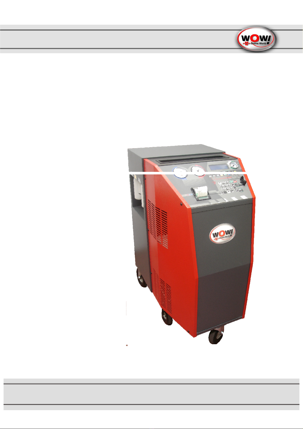
Automatic A/C-Service Unit
2
Letzte Änderung: 24.06.2009 / Art.Nr.: 2059ENG
CONTENTS
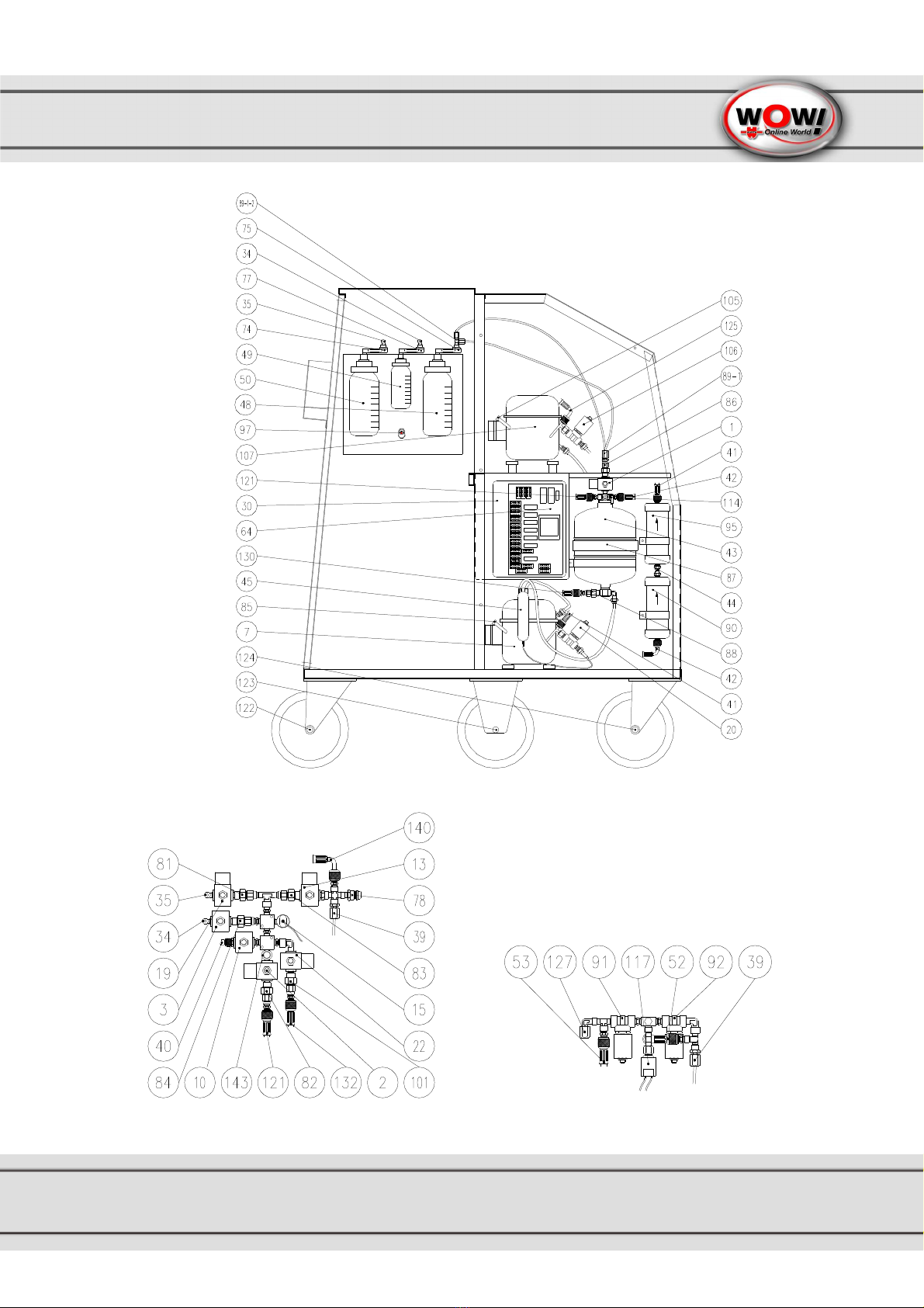
Layout drawing .......................................................................................................................5
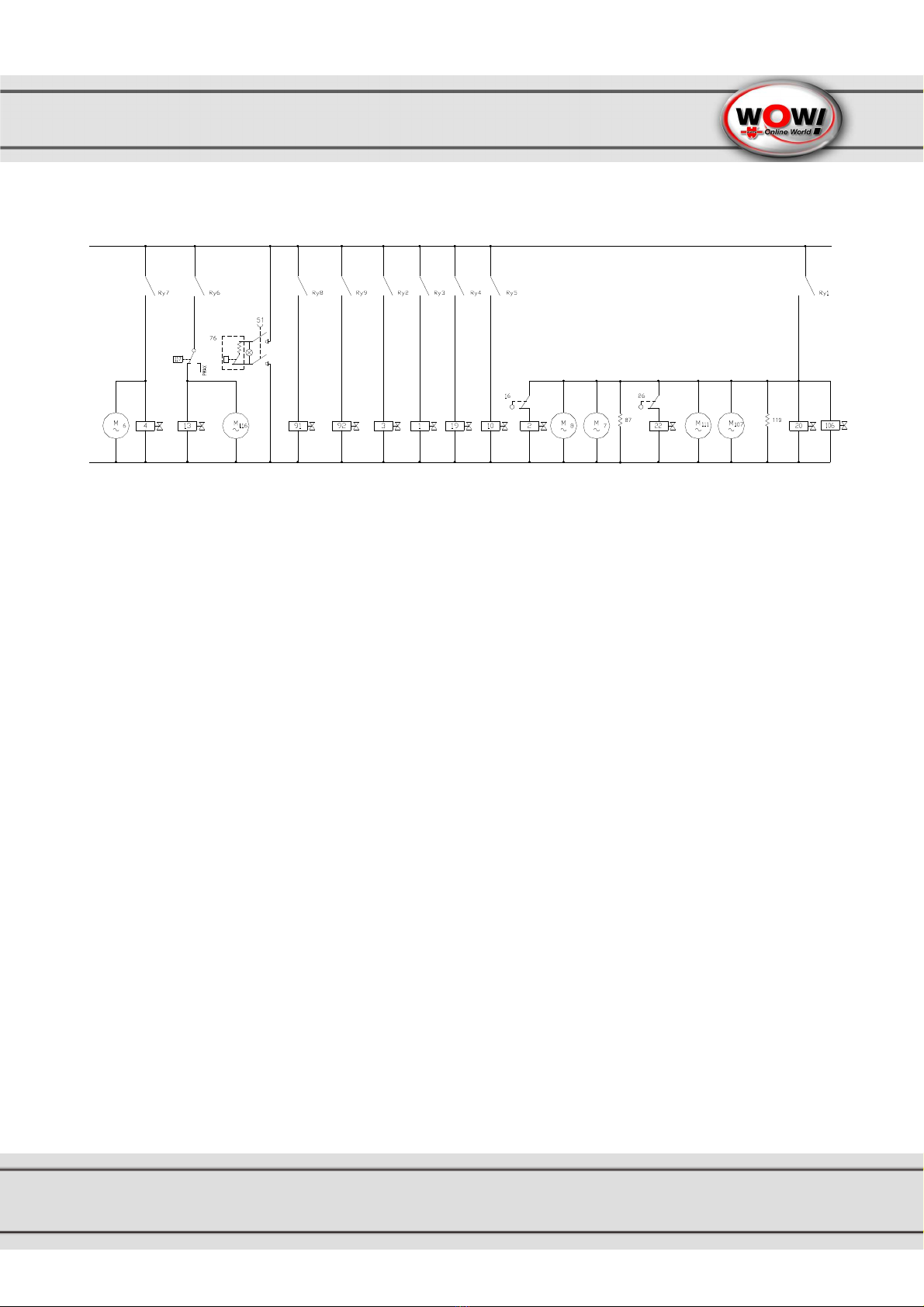
Electric scheme ......................................................................................................................9
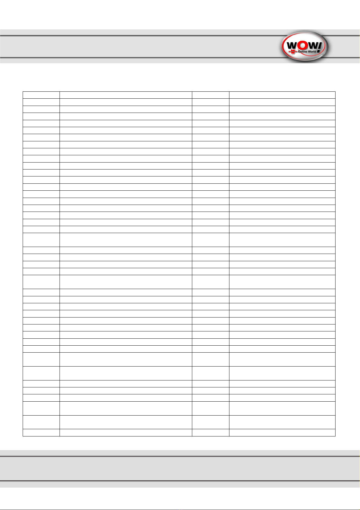
Legend...................................................................................................................................10
1. Introduction to Coolius 40000 BUS recovery unit ......................................................12
1.1
Technical specifications................................................................................................................... 12
2. Components description and standard equipment....................................................12
2.1
High vacuum pump ......................................................................................................................... 12
2.2
Refrigerant charging pump.............................................................................................................. 12
2.3
Refrigerant bottle............................................................................................................................. 12
2.4
Distiller - separator.......................................................................................................................... 13
2.5
Compressor .................................................................................................................................... 13
2.6
Filters.............................................................................................................................................. 13
2.7
Flexible hoses................................................................................................................................. 13
2.8
Quick coupler valves....................................................................................................................... 13
2.9
Printer............................................................................................................................................. 13
2.10
Temperature probe ......................................................................................................................... 13
2.11
Control module................................................................................................................................ 13
2.12
Functions programming................................................................................................................... 13
2.13
Functions that can be performed..................................................................................................... 14
3. Control panel..................................................................................................................15
3.1
Description of the control keys......................................................................................................... 15
4. Preparing the unit Coolius 4000 BUS for operation..................................................16
4.1
Checking the vacuum pump oil level................................................................................................ 16
4.2
Unlocking the scale......................................................................................................................... 16
4.3
"Zero" scale check .......................................................................................................................... 17
4.4
Filling refrigerant into the bottle ....................................................................................................... 17
4.4.1
Filling refrigerant into the internal bottle by means of recovery from the service bottle...................... 17
4.4.2
Emptying the internal bottle............................................................................................................. 19
5. Recovery ........................................................................................................................20
5.1
Preparing the vehicle for refrigerant recovery from the A/C system.................................................. 20
5.2
Refrigerant recovery for R= all......................................................................................................... 20
5.3
Refrigerant recovery for R<>00.00................................................................................................... 21
6. Draining of the oil extracted from the A/C system......................................................22
7. Evacuating and checking the A/C system for tightness ............................................22
8. Refilling oil into the A/C system...................................................................................23
8.1
Warning .......................................................................................................................................... 23
8.2
Warning .......................................................................................................................................... 23
8.3
Oil refilling procedure in the A/C system.......................................................................................... 23
8.4
Suggested oil quantities for refilling the vehicle air conditioner......................................................... 24
8.5
Warning .......................................................................................................................................... 24
8.6
UV refilling procedure in the A/C system.......................................................................................... 24
9. Charging refrigerant into the A/C system................................................................25
9.1
Warning .......................................................................................................................................... 25
9.2
A/C system refrigerant charging procedure...................................................................................... 25
10. Checking the A/C system operating pressures.......................................................25
11. FLUSHING automatic function..................................................................................26
12. FIRE&GO automatic function....................................................................................26
13. AUTO function............................................................................................................27
14. Operations before disconnecting the unit from the A/C system ...........................27