manuals.online logo
Brands
  1. Home
  2. •
  3. Brands
  4. •
  5. Wowings
  6. •
  7. Aircraft
  8. •
  9. Wowings Booby Instructions for use

Wowings Booby Instructions for use

Other Wowings Aircraft manuals

Wowings Skua 1500 Instructions for use

Wowings

Wowings Skua 1500 Instructions for use

Wowings Duck Instructions for use

Wowings

Wowings Duck Instructions for use

Popular Aircraft manuals by other brands

Skywalk Mescal 4 instruction manual

Skywalk

Skywalk Mescal 4 instruction manual

Cessna U206G STATIONAIR Pilot operating handbook

Cessna

Cessna U206G STATIONAIR Pilot operating handbook

Cirrus SR22 Maintenance manual

Cirrus

Cirrus SR22 Maintenance manual

Schleicher ASK 21 Assembly & Disassembly

Schleicher

Schleicher ASK 21 Assembly & Disassembly

Cirrus SR20 Maintenance manual

Cirrus

Cirrus SR20 Maintenance manual

Skywalk Tequila 2 Manual/service

Skywalk

Skywalk Tequila 2 Manual/service

MAULE M-7-235B Airplane Flight Manual

MAULE

MAULE M-7-235B Airplane Flight Manual

Tecnam P92 Echo Super Maintenance manual

Tecnam

Tecnam P92 Echo Super Maintenance manual

Wills Wing HP II Owner's and service manual

Wills Wing

Wills Wing HP II Owner's and service manual

MAULE MX-7-180B Airplane Flight Manual

MAULE

MAULE MX-7-180B Airplane Flight Manual

Ozone ZENO 2 Pilot's manual

Ozone

Ozone ZENO 2 Pilot's manual

Boeing 737 Quick reference handbook

Boeing

Boeing 737 Quick reference handbook

MHD MHDFLY TINY GLIDER Z5630 Manual and using instructions

MHD

MHD MHDFLY TINY GLIDER Z5630 Manual and using instructions

Ozone Roadster Pilot's manual

Ozone

Ozone Roadster Pilot's manual

SpeedWing Mini SpeedWing EX Assembly instructions

SpeedWing

SpeedWing Mini SpeedWing EX Assembly instructions

Daher-Socata TBM 900 Pilot's information manual

Daher-Socata

Daher-Socata TBM 900 Pilot's information manual

Aircraft REIMS F152 Flight manual

Aircraft

Aircraft REIMS F152 Flight manual

Cessna 172 Skyhawk SERIES owner's manual

Cessna

Cessna 172 Skyhawk SERIES owner's manual

manuals.online logo
manuals.online logoBrands
  • About & Mission
  • Contact us
  • Privacy Policy
  • Terms and Conditions

Copyright 2025 Manuals.Online. All Rights Reserved.

- 1 -
Wowings Booby
CONSTRUCTION MANUAL
Copyright 2005 Wowings
www.wowings.com
- 2 -
Thank you very much for purchasing the Booby. Although made primarily of soft EPP foam, this
RC slope glider is still capable of causing significant damage to property and serious personal
injury or death to bystanders or yourself. Please ensure that you fly this model in a safe and
responsible manner and obey your local laws and regulations. By building and/or flying the Booby
you assume all responsibility for any damage or injury it may cause. Wowings accepts no liability
for any damage or injury caused by our products. If you do not agree to these terms, please contact
your place of purchase prior to commencing construction to arrange returning this kit for a refund.
Now onto the fun stuff…First, please ensure that nothing is missing from the Booby kit and that
none of the contents have been damaged. If anything is missing or damaged please contact your
place of purchase immediately to make arrangements for replacement parts to be supplied. Your
Booby kit should contain the following:
•2 x EPP foam wing outer panel segments (each with two panels joined together)
•1 x EPP foam wing central panel
•2 x lengths of black fiberglass spar
•5 x lengths of balsa (two marked with outlines for ailerons, two marked for trailing edge
pieces and one for elevator)
•3 x steel pushrods with clevises attached
•1 x piece of coreflute marked with outlines for two fins
•1 x black fiberglass internal spar joiner
•2 x packs of Dubro nylon control horns (total of 4 control horns)
•2 x packs of Dubro E-Z connectors (total of 4 connectors)
•This construction manual!
To complete the kit you will require the following tools and supplies:
•Sharp trimming knife (large retractable disposable type is ideal)
•Sandpaper and sanding block, screwdriver, drill, pliers and ruler
•48mm (2”) wide cross-weave filament tape
•Covering material (eg. coloured packing tape or iron-on film such as UltraCote or Profilm)
•3M “Super 77” or 3M “Multi-Purpose” spray adhesive
•5 minute epoxy glue (eg. Selley’s Araldite)
•Goop/Goo glue (eg. Pacer’s Zappa-Dappa-Goo II or Second Wind’s Shoe Goo II) or
Polyurethane glue (eg. Selley’s Durabond, Gorilla Glue or Elmer’s ProBond) or 30 minute
epoxy glue (not ideal).
•Hot-melt glue –not essential
•1mm (1/16”) thick lead flashing and/or lead pieces for nose weight
The following radio equipment is recommended:
•Rechargeable receiver battery pack (4 x AA size cells) in flat configuration.
•Receiver (minimum 2 channel)
•2 x standard size servos (eg. BlueBird BMS-621, GWS S03TXF, Hitec HS-322)
•1 x mini servo or metal-geared micro servo (eg. BlueBird BMS-380MG, GWS MINI, GWS
S3002, Hitec HS-85MG)
•1 x 300mm (12”) servo extension lead for one of the aileron servos
•1 x “Y” lead for the aileron servos
- 3 -
Read through the following instructions entirely prior to starting so that you have an overview of
what is involved. Please don’t be tempted to deviate from these instructions unless you are an
experienced builder and are certain that your changes won’t negatively affect the structural integrity
or flying performance of the Booby. These instructions are based in metric units but I have also
tried to include the equivalent imperial measurement as much as possible. For your reference, 1
inch (”) equals 25.4 millimeters (mm). These instructions are also available in colour as a MS Word
document online at www.wowings.com/instructions/wowings_booby.doc
SPAR INSTALLATION
Polyurethane (PU) glue is probably the best option for gluing in the wing spar. It foams up and
expands during the curing process and penetrates into the surrounding EPP foam creating a strong
tight bond without adding a lot of weight. However, if not used properly it can create a mess and
possibly even ruin the wing. For this reason, these instructions will focus on using more fool-proof
glues instead. If you decide to try using a PU glue for the first time, it’s best to experiment a little
on some scrap EPP before applying it to your wing. Ensure there’s a layer of waxed paper between
then wing and the bottom wing bed because the PU glue penetrates through the EPP easily. Be
sparing with the amount of PU glue used and wipe the spar with a damp cloth prior to gluing in
place to help the glue activate. Ensure that the wing is adequately weighted down in its beds while
the glue is curing.
If you want your Booby to be compliant with EPP slope combat competition rules, you may need to
trim the spar by about 25mm (1”) at the wingtips before gluing in place so that it is set back far
enough from the wing’s leading edge. Please consult your local rules for specific requirements.
1. Locate the two lengths of black fiberglass spar and the internal spar joiner. Use 5 minute
epoxy glue to attach the two spar halves together over the internal joiner, creating a full
length straight spar.
2. Remove the foam wing cores from their beds. Gently bend open the spar slot and carefully
remove the foam “noodle” from the spar channel. Trial fit the spar to ensure that no bits of
foam have been left in the spar channel. It should fit easily without the spar slot opening
being forced apart. Also check for acceptable alignment of the two outer wing sections with
the central wing panel. Remove the spar and put it aside to be used shortly.
3. Glue the two outer wing sections to either side of the central wing panel using hot-melt glue
or spray adhesive (epoxy is also OK but a little brittle). Align with the panels’ spar slot and
ensure the top and bottom surface of each panel is also flush.
4. Lightly sand the fiberglass spar to roughen its surface and remove any remaining mold
release agent and wipe off the dust.
5. Gently bend open the spar slot and run a bead of goop/goo style glue (30 minute epoxy is
also OK but not as good) inside the spar channel. Starting at one wing tip, bend open the
spar slot and push the spar down into the spar channel. Once the spar has been inserted, use
a piece of dowel, or back of a pen or pencil, to push the spar firmly all the way down into
the channel so that the glue is forced up and around the spar, coating it entirely. This process
can also be helped by repeatedly bending the wing chord-wise, temporarily closing and
opening the spar slot to help work the glue around the spar and centre the spar in the spar
channel. Wipe off any excess glue.
6. Place the entire wing back into its foam beds and rest it on a completely flat surface (eg.
table or floor). Weight it down so that the wing is kept flat and completely snug with the
bottom curve of its foam beds. To avoid deforming the foam make sure the weights aren’t
- 4 -
too heavy and that they are spread fairly evenly. Plastic shopping bags partly filled with
sand make ideal weights. It may be easier if you remove the top portion of the wing beds by
cutting along the leading edge. Leave overnight (or as per glue’s instructions) in this
position while the glue fully cures.
WING ASSEMBLY
7. Locate the five (5) pieces of balsa wood. Two are marked out for the two fixed trailing edge
pieces and two are marked out with the two ailerons. The fifth blank piece will be used for
the elevator. Using a fine-toothed mitre saw or sharp knife, cut out the trailing edges and
ailerons along the outlines marked.
8. Hold the trailing edge pieces up against the foam trailing edge of the panels to either side of
the central wing panel to make sure they fit nicely. The bottom surface of the balsa trailing
edges is the one with the smoother cut surface that had the cut-out lines marked on them
(and the one that meets its leading edge at a 90 degree angle). When butted up against the
foam sub-trailing edge, the bottom surface of the balsa trailing edge piece should form a
continuation of a straight line from the rear half of the airfoil shape.
9. Once you are happy that they will fit
nicely, round off the top and bottom edges
of both ends of each balsa trailing edge
piece to make covering easier later on.
10. Use 5 minute epoxy or hot-melt glue to
glue one of the balsa trailing edge pieces to
the foam. Hold in place with masking tape
if needed and use a straight edge (ruler)
held against the rear section of the bottom
of the wing and the bottom of the balsa
trailing edge to ensure correct alignment.
Once the glue has cured, repeat this
process for the second balsa trailing edge
piece.
11. Trim and/or sand off any excess glue along the trailing edge joints. Ensure that there is a
smooth progression from the foam to the balsa so that it forms a nice continuation of the
wing’s slightly reflexed airfoil shape.
12. Using a sanding block, sand a 45 degree
bevel along the leading edge of each balsa
aileron, with the 45 degree opening on
their bottom surface (ie. hinged on top
surface).
13. Round off the top and bottom edges of
each end of both ailerons to make covering
easier and put them aside to be installed
later.
14. Using the unmarked balsa elevator piece,
hold it above the foam sub-trailing of the
wing's central panel. Mark its correct
length so that it fits in-between the two
balsa fixed trailing edge pieces with a small gap of around 2mm (3/32”) either side to allow
for free movement once everything is covered. Cut the balsa elevator piece to length.
- 5 -
15. As per ailerons, sand a 45 degree bevel along the leading edge of the balsa elevator, with the
45 degree opening on its bottom surface (ie. hinged on top surface).
16. As per ailerons, round off the top and bottom edges of each end of the balsa elevator piece
and put it aside to be installed later.
17. Round off the top and bottom edges of each wing tip using a sharp knife. You may also wish
to round the leading edge corners of the wing tips when viewed from above.
18. Locate the piece of coreflute supplied in the kit and cut out the two fins as marked.
19. Mark out where the slots for the fins will go on the wing. You’ll need a slot 2mm to 3mm
(3/32” to 1/8”) wide and 75mm (3”) long, with the back of the slot starting 100mm in front
of the wing’s trailing edge (trailing edge of the balsa). It should be positioned just outboard
from the panel join line so you don’t have to cut through the glue.
20. Cut out the slots with a very sharp blade, being extra careful to keep the cuts vertical. Poke
out the foam from the slots with the end of a ruler or a metal pushrod.
21. Test fit the fins to ensure they fit tightly in the foam in a vertical position and that their
trailing edge is in line with the wing’s trailing edge. When pushed all the way down they
should butt up against the contour of the top surface of the wing. Remove the fins and put
them aside for later.
RADIO EQUIPMENT INSTALLATION
If you want your Booby to be compliant with EPP slope combat competition rules, you may need to
position your battery pack and/or nose-weight further back than instructed. Please consult your local
rules for specific requirements. Doing this will increase the all-up weight of the finished model a
little due to the extra nose-weight required to balance correctly.
22. Gather together all the radio equipment you plan to install into the glider and test that it is all
working properly. If your transmitter and receiver batteries are not fully charged, charge
them now.
23. Once the glue for the spar has cured, remove the weights and foam beds from the wing. It’s
now time to install the radio equipment.
24. Draw a line 30mm (1 3/16”) back from the
leading edge of the outer wing panels near
each nose. Draw another line 20mm (3/4”)
back from the leading edge of the inner
panels near each nose. For safety and
durability reasons nothing should be
embedded into the foam in front of these
lines
25. Lay your receiver’s flat battery pack
squarely on top of the wing at one of its
noses so that two of the battery pack’s
corners are touching the lines you just
marked. Trace around it with a pen and
then cut around this outline all the way through the foam. Remove this foam plug and draw
a line vertically up its front side for later reference.
26. Hold the side of your battery pack against the side of the foam plug so that it is centered and
trace lines to mark out the thickness of your battery pack. Repeat this for all four sides and
then cut off a bottom slice (base) and a top slice (lid) along these outlines. Mark the top of
the slices with an “x” for later reference and discard the remaining piece of the plug.
- 6 -
27. Using hot-melt glue (best), spray adhesive
(sprayed into a puddle and then spread on)
or 5 minute epoxy (not ideal), glue the base
slice back into the bottom of the battery
cut-out hole, creating a base for the battery
recess. Use the markings you made to
orientate it correctly, ensuring a perfect fit.
28. Mark out the same size area (approx.
50mm x 55mm) in the same position on the
other nose. This recess will be used later
for accommodating weight in the form of
layers of 1mm (approx. 1/16”) lead
flashing to balance the glider correctly.
Make the base slice of this recess a little thicker, say 10mm (3/8”). Put the remainder of the
foam plug aside for later use.
29. Next are the servo recesses. Decide whether you want to remove your servos’ mounting
lugs. These are generally not required for foam gliders and removing them can make
mounting into foam a little simpler. Base
your decision on the likelihood of requiring
the mounting lugs on the servos for a
different style of model in the future and
the availability and expense of replacement
servo cases.
30. Lay one of your standard size aileron
servos on top of the wing slightly outboard
(towards the wing tip) of the battery pack
recess so that there’s 10mm (3/8”) of foam
between it and the edge of the battery pack
recess and so that one of its corners (or
servo mounting lugs) is touching the line
you marked 30mm (1 3/16”) back from the leading edge. The servo needs to be aligned so
that the servo arm movement is at right angles to the spar (or parallel with the line of flight).
Trace around the servo and cut around this outline with a sharp knife all the way down
through the foam. Push out the foam plug and mark with a vertical line down its front side
for later reference.
31. Hold the side of your servo against the side
of the foam plug flush with the top surface
and trace out a line. Repeat this for all four
sides and then cut off a bottom slice along
this outline. Mark the top of this slice with
an “x” for later reference and discard the
remaining piece of the plug.
32. Glue the bottom slice of the foam plug into
the bottom of the servo cut-out hole
forming a base for the servo recess. Use the
marks on its front side and top to orientate
it correctly, ensuring a perfect fit.
33. Repeat this process for the second aileron
servo recess on the other side of the wing.
- 7 -
34. Draw a line 5mm (3/16”) back from the
edge of the spar slot in the middle of the
central wing panel. Draw another line at
right angles to this in the exact middle of
the wing running a little way towards the
trailing edge.
35. Lay you mini size elevator servo on top of
the wing so that one of its sides (or
mounting lugs) is up against the line you
marked 5mm (3/16”) back from the spar
slot and its servo arm is in line with the
line you marked as the middle of the wing.
Trace around the servo and repeat the
process of a creating a servo cavity as per the aileron servos.
36. Next to the recesses for each of the servos,
mark out the area required to accommodate
the servo arm and its movement. The area
will be about 10mm wide by 20mm long
(3/8” by 3/4”). Cut out a triangular shaped
wedge down to the depth of the servo
recess’s floor.
37. Choose a place for your receiver that is
5mm (3/16”) back from the edge of the
spar slot and to one side (closer to the
battery pack) of the central wing panel. If
possible, position it so that it can be easily
reached by the leads of the battery pack,
elevator servo and one of the aileron servos without the need for extension leads. The other
aileron servo will usually require a 300mm (12”) extension lead.
38. Trace around the receiver with a pen and then cut out along this outline all the way down
through the foam. Remove this foam plug and mark its front side with a vertical line for later
reference.
39. Decide whether you want to mount your receiver flush with the top surface of the wing or
embed it beneath the surface. Base this decision on the layout and size of your receiver and
whether you intend to use a switch or plug the battery plug directly into the receiver. I
personally try to use receivers that have the plug sockets on the top surface (and preferably
the crystal as well) and mount them flush
with the top surface of the wing. This
means the servo plugs are sticking up
proud from the wing surface (adding a little
extra drag and ugliness) however this
makes it simple and convenient to just plug
in and take out the battery lead to turn it on
and off and have easy access for charging.
40. Hold the side of your receiver against the
side of the foam plug in the desired
position (eg. flush with the top surface) and
trace the line(s). Repeat this for all four
sides and then cut off a bottom slice along
- 8 -
this outline, and a top slice if you’ve decided to have your receiver embedded below the
surface. Mark the top of the slice(s) with an “x” for later reference and discard the remaining
piece of the plug.
41. Glue the bottom slice of the foam plug into
the bottom of the receiver cut-out hole
forming a base for the receiver recess. Use
the marks on its front side and top to
orientate it correctly, ensuring a perfect fit.
If you have a top slice, put it aside for later
use as lid over the receiver.
42. Mark out an area next to the receiver to
accommodate the excess length in the
battery and servo leads. An area
approximately 30mm by 40mm (1 3/16” by
1 9/16”) is usually plenty. Cut out a foam
plug using the same method used for the
receiver and servo recesses and glue back in a 5mm to 10mm (3/16 to 3/8”) slice to form a
base. Keep the remainder of the foam plug for later use.
43. Decide if you wish to install an optional
ballast system such as ballast boxes or
ballast tube(s). Ballast is removable lead
weight positioned exactly on the glider’s
centre of gravity (CG) so that it increases
the model’s weight without affecting the
model’s point of balance. Increasing the
Booby’s weight (higher wing-loading) will
improve it’s penetration in very windy
conditions (over 30 knots) resulting in
increased speed. Given that the Booby
already has quite a high wing-loading
when un-ballasted and is a fast low drag
design, we do not believe that provision for ballast is necessary, so simply mention it here as
an option without going into installation details. If two ballast boxes or two ballast tubes are
installed they can be positioned at the Booby’s CG (140mm back from the noses) in the
middle of each intermediary panel (between central wing panel and outer panel). A single
ballast tube should also be able to fit into the leading edge of the central panel at the CG but
would forfeit compliance with combat competition rules.
44. Cut slits into the top surface of the wing to accommodate the battery lead and servo leads.
The receiver antenna should be kept a little clear (and avoid any crossing) of the servo leads,
battery leads and spar to avoid possible interference with the radio signal from the
transmitter. Cut a slit for the receiver
antenna that loops around the fin slot and
then runs about 20mm (3/4”) in from the
central panel’s foam sub-trailing edge and
then out to the wingtip.
45. Fit the battery pack, receiver and servos
into their recesses. Plug everything
together and test that it is working
correctly. The two standard size aileron
- 9 -
servos plug into your receiver’s aileron channel via the “Y” lead, with the servo on the other
side of the wing requiring a servo extension lead (300mm). The mini size elevator servo is
plugged into the elevator channel of your receiver.
46. Make sure the servo arms are centered in the correct position when everything is turned on
and the transmitter trims are in their neutral position. The servo arms should be pointing
directly upwards, or leaning just slightly rearwards. Unscrew the servo arms and adjust if
required. Also check for correct direction of servo travel and reverse via your transmitter if
required. Viewed from above, when your transmitter’s elevator stick is pulled back for “up”
control, your elevator servo’s arm should move forwards (towards the leading edge of the
wing), and should move backwards when “down” control is applied. When your
transmitter’s aileron stick is moved to the right for “right roll” control, the right aileron
servo’s arm should move forwards and the left aileron servo’s arm backwards, and opposite
when “left roll” control is applied.
47. Perform a “range check” for your radio equipment now. You should be able to control the
servos smoothly with no “jitters” from 10 paces away with your transmitter’s aerial fully
retracted (not extended at all).
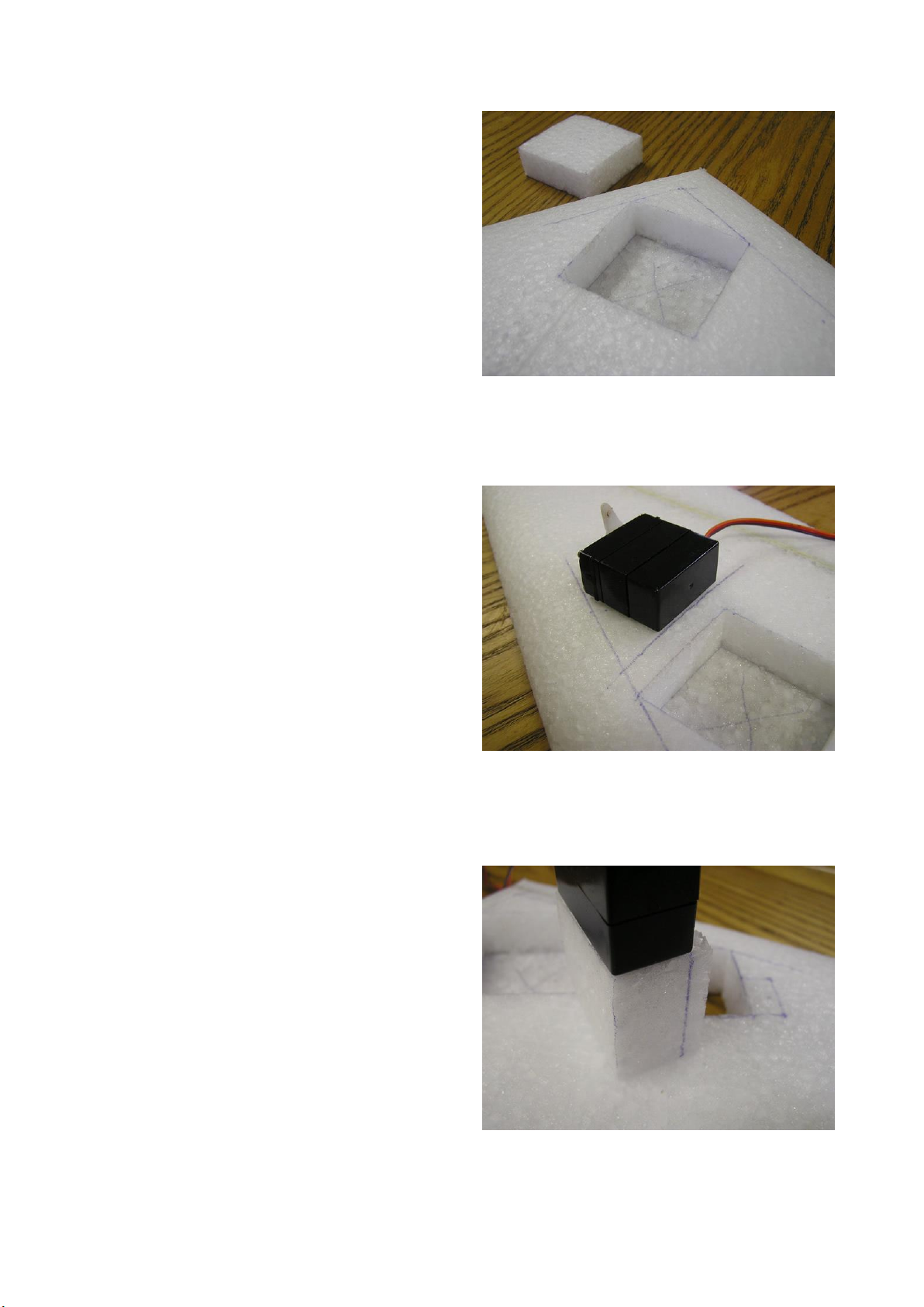
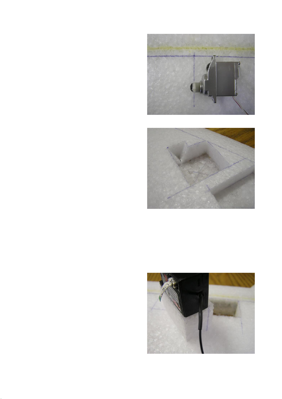
48. Once you are satisfied that your radio equipment is functioning correctly, it’s time to start
building it into your glider. Soon, retrieval of radio equipment will require some surgery on
your glider, so it is best to make any necessary adjustments or repairs now. Also keep in
mind that you will need to have access to a means of charging your receiver’s battery pack
once it is embedded into the glider. This can be by means of a special switch with charging
socket, or as simple as having access to the battery pack’s plug (perhaps just having it plug
into an exposed socket of your receiver). If installing an exposed switch, orientate it so that
the “on” position is towards the rear of the glider so that if it brushes up against something
while flying it doesn’t switch off.
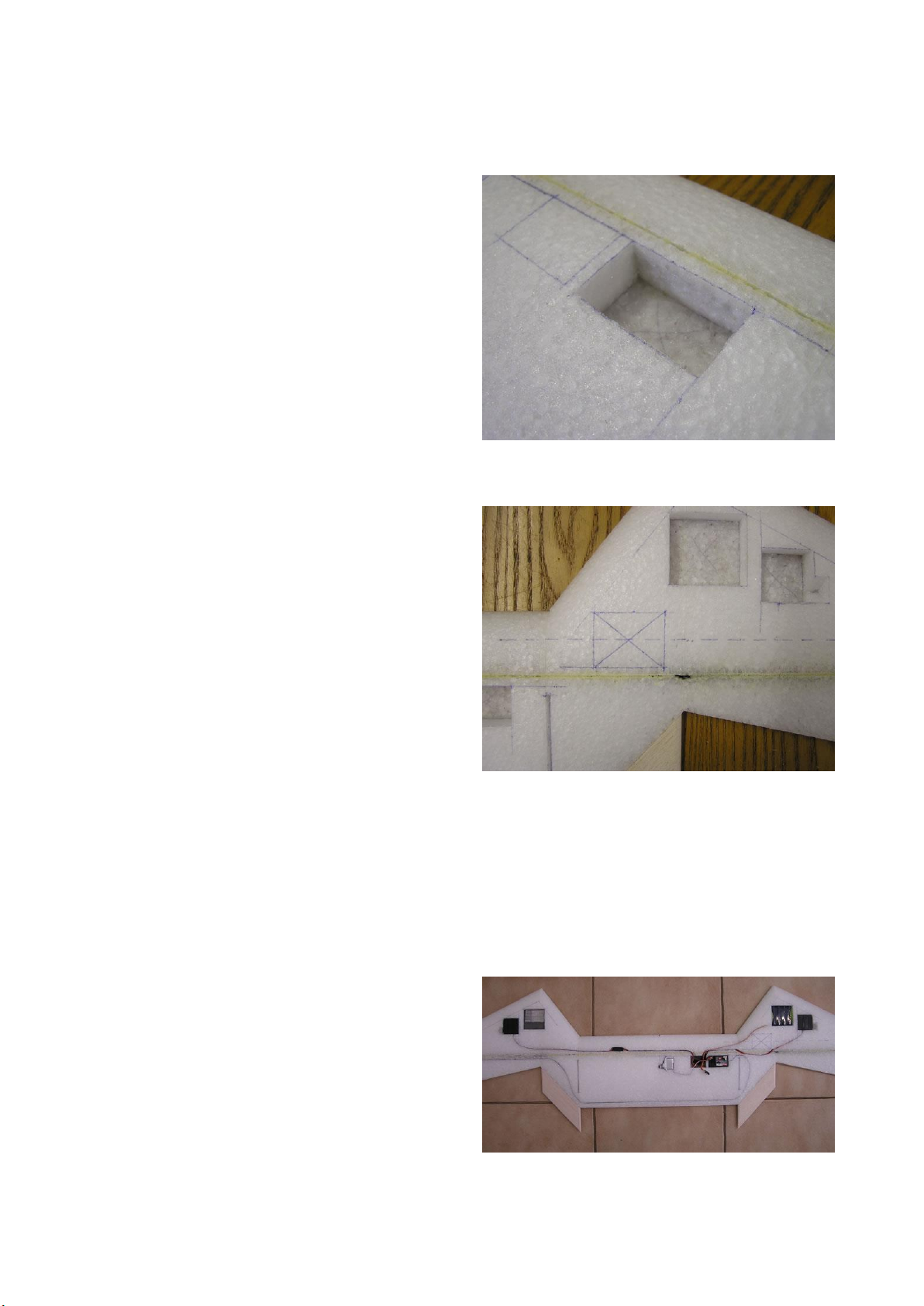
49. Coil up the excess length in the leads and insert into the recess you made next to the
receiver. Slice off an appropriate thickness from the top of the remains of this cavity’s foam
plug to form a lid and glue it in place flush with the top surface of the wing.
50. If you chose to embed your receiver below the wing surface, glue the top slice from your
receiver’s foam plug in place now so that it is flush with the top surface of the wing.
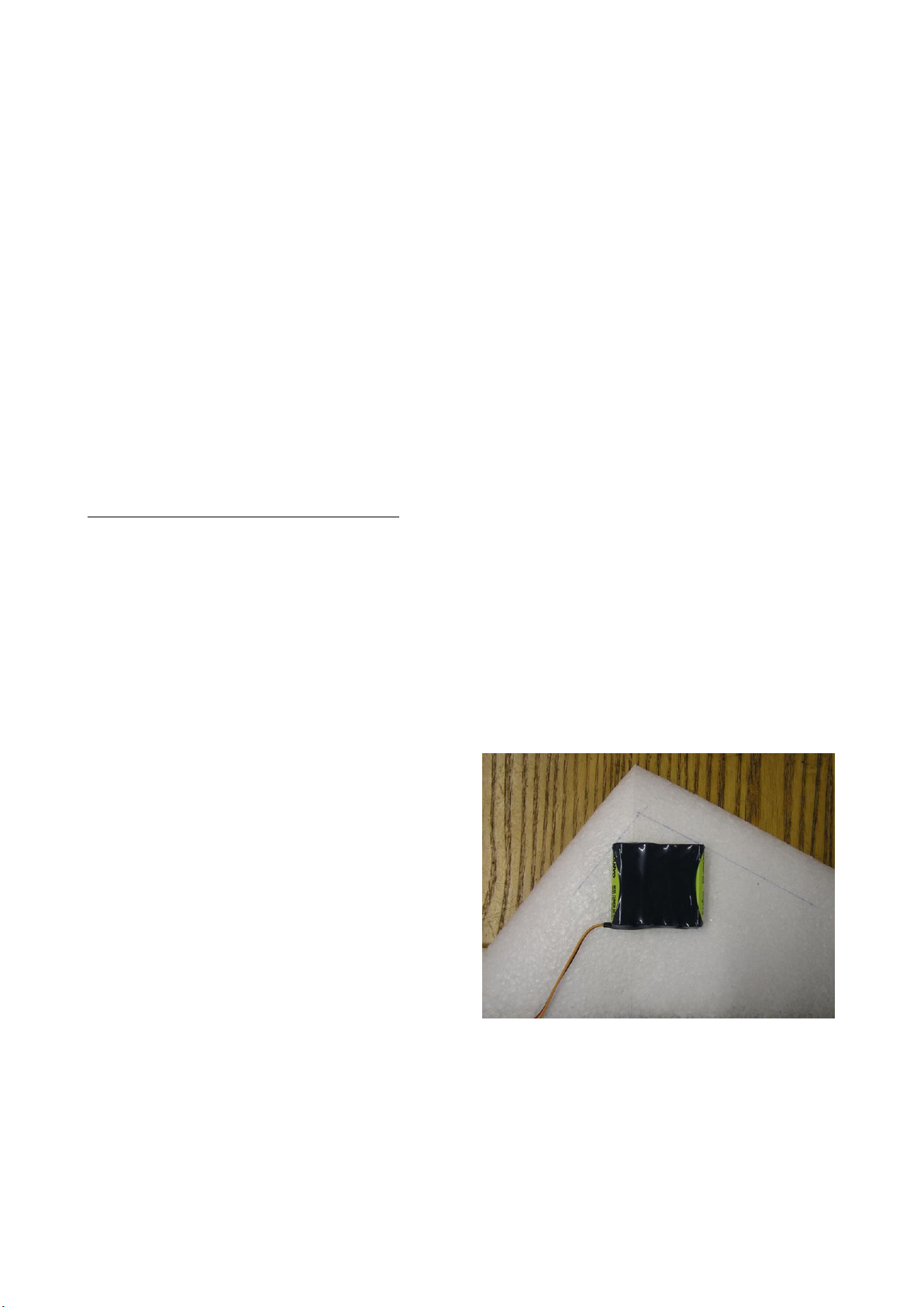
51. Glue the top slice of your battery pack’s foam plug so that it is flush with the top surface of
the wing.
52. Mark the mid point of the central wing panel towards its leading edge.
53. Cut 3 pieces of lead from a flat sheet of 1mm thick lead flashing, each measuring the same
size as your battery pack’s recess (approx. 50mm x 55mm).
54. Insert enough lead into the recess on the glider’s other nose (the one that doesn’t contain the
battery pack) so that the glider balances exactly at the mid point you marked on the central
wing panel. It will likely require around 2 ½ pieces of the lead flashing (approx. 100 to 110
grams). If the final piece is not a full piece, place it as far forward in the recess as possible
and tape it with some filament tape to the piece which is underneath to prevent it from
shifting.
55. Measure the distance at each corner from the top of the lead to the top surface of the wing.
Cut a slice of appropriate thickness from the top of the remains of this cavity’s foam plug to
form a lid. Glue this in place so that it is flush with the wing’s top surface.
56. Cut and/or sand off any excess glue from around the foam plugs so that they’re all flush
with the surface of the wing.
- 10 -
TAPING & COVERING
These instructions are based on using 48mm/50mm (2”) wide strapping tape with fiberglass
filaments, hereto referred to simply as “filament tape”. We recommend using the cross-weave
variety throughout. However, for those of you wanting to keep weight to a minimum (sacrificing a
little strength and durability), this can be replaced in many instances by the uni-directional (length-
wise filaments) variety or even just 36mm (1 1/2”) wide filament tape (uni-directional filaments). In
instances when it’s crucial to stick with the 48mm/50mm (2”) cross-woven filament tape we will
refer to “cross-weave filament tape”.
The instructions also assume covering with 48mm/50mm (2”) wide coloured polypropylene tape
due to its simplicity and cheapness. Those who wish to spend a little extra money and care can use a
variety of other covering materials such as Ultracote, Oracover and Profilm. These iron-on
coverings provide a much nicer finish but are a little trickier to apply correctly. If using an iron-on
covering, be sure not to use too high a heat or it may deform (melt) the foam. Also be careful not to
introduce any warps or twists into the wing when shrinking the covering. 3M Super 77 (“multi-
purpose”) spray adhesive is still required when using an iron-on covering.
57. Thoroughly remove all dust from the glider and your work area.
58. Use masking tape to mask off any exposed radio equipment that you don’t want to get
sprayed with glue.
59. Go outside and spray the entire bottom surface of the wing with 3M Super 77 (“multi-
purpose”) spray adhesive and then place it upside down on a cardboard box (or anything
else to keep it up off your work surface). Let the spray adhesive dry for about 5 minutes (or
until aggressively tacky).
60. Now it’s time to apply the filament tape. This provides essential tensile strength to the EPP
foam wing and helps to keep the glider rigid during flight. For each piece of tape applied,
overhang the wing by 25mm to 50mm (1” to 2”) and wrap around to the opposite surface of
the wing. When a piece ends at the balsa trailing edge, you can just cut if off flush with the
edge (don’t wrap around). Rub each piece that is laid down with some fine sandpaper to
remove any release agent from the tape’s backing for better adhesion of subsequent layers of
tape, spray adhesive and covering. Thoroughly wipe off any dust that is created each time.
61. Apply strips of filament tape to the bottom surface of the wing as per the above illustration.
62. Then, lay a piece of cross-weave filament tape along the spar line and wrap around at the
tips. Position so that about 1/3 of the width of the tape is behind the spar and 2/3 in front.