TABLE OF CONTENTS
2
TABLE OF CONTENTS
1 MEANS OF REPRESENTATION........................ 3
1.1 Symbols used ....................................... 3
1.2 Formats used........................................ 3
2 SAFETY ADVICE ............................................... 4
2.1 Use definition –intended use ............... 4
2.2 Misuse................................................... 4
2.3 Safety advice ........................................ 4
2.4 Degrees of risk and symbols ................ 4
2.5 Safe operation....................................... 5
2.6 Work rules............................................. 5
2.7 Environment.......................................... 5
2.8 Owner's Manual.................................... 5
2.9 Correct installation................................ 6
2.10 Chassis tightening torques ................... 6
3 IMPORTANT NOTES ......................................... 7
3.1 Manufacturer and implied warranty...... 7
3.2 Fuel, auxiliary substances..................... 7
3.3 Spare parts, accessories ...................... 7
3.4 Service .................................................. 7
3.5 Figures .................................................. 7
3.6 Customer service.................................. 7
4 SERIAL NUMBERS............................................ 8
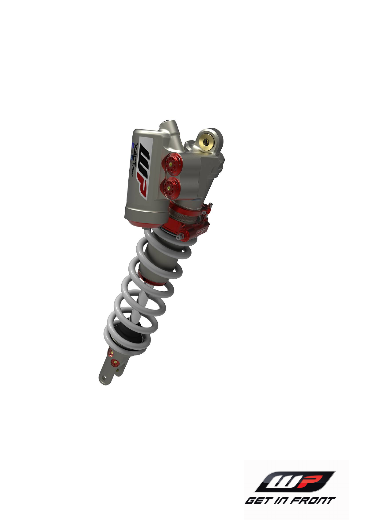
4.1 Shock absorber article number ............ 8
5 PREPARING FOR USE...................................... 9
5.1 Advice on preparing for first use........... 9
6 RIDING INSTRUCTIONS ................................. 10
6.1 Checks and maintenance measures
when preparing for use....................... 10
7 SERVICE SCHEDULE...................................... 11
7.1 Additional information......................... 11
7.2 Required work..................................... 11
7.3 Recommended work........................... 11
8 SERVICE WORK ON THE CHASSIS ............... 12
8.1 Raising the motorcycle with a lift
stand ................................................... 12
8.2 Removing standard shock
absorber .......................................... 12
8.3 Installing the WP PRO
COMPONENTS shock absorber ..... 12
8.4 Removing the motorcycle from the
lift stand .............................................. 12
9 TUNING THE CHASSIS................................... 14
9.1 Checking the basic chassis setting
with rider's weight............................... 14
9.2 Compression damping of the shock
absorber.............................................. 14
9.3 Shock absorber rebound damping..... 14
9.4 Adjusting the low-speed
compression damping of the shock
absorber.............................................. 15
9.5 Adjusting the high-speed
compression damping of the shock
absorber.............................................. 15
9.6 Adjusting the low-speed rebound
damping of the shock absorber.......... 16
9.7 Adjusting the high-speed rebound
damping of the shock absorber.......... 17
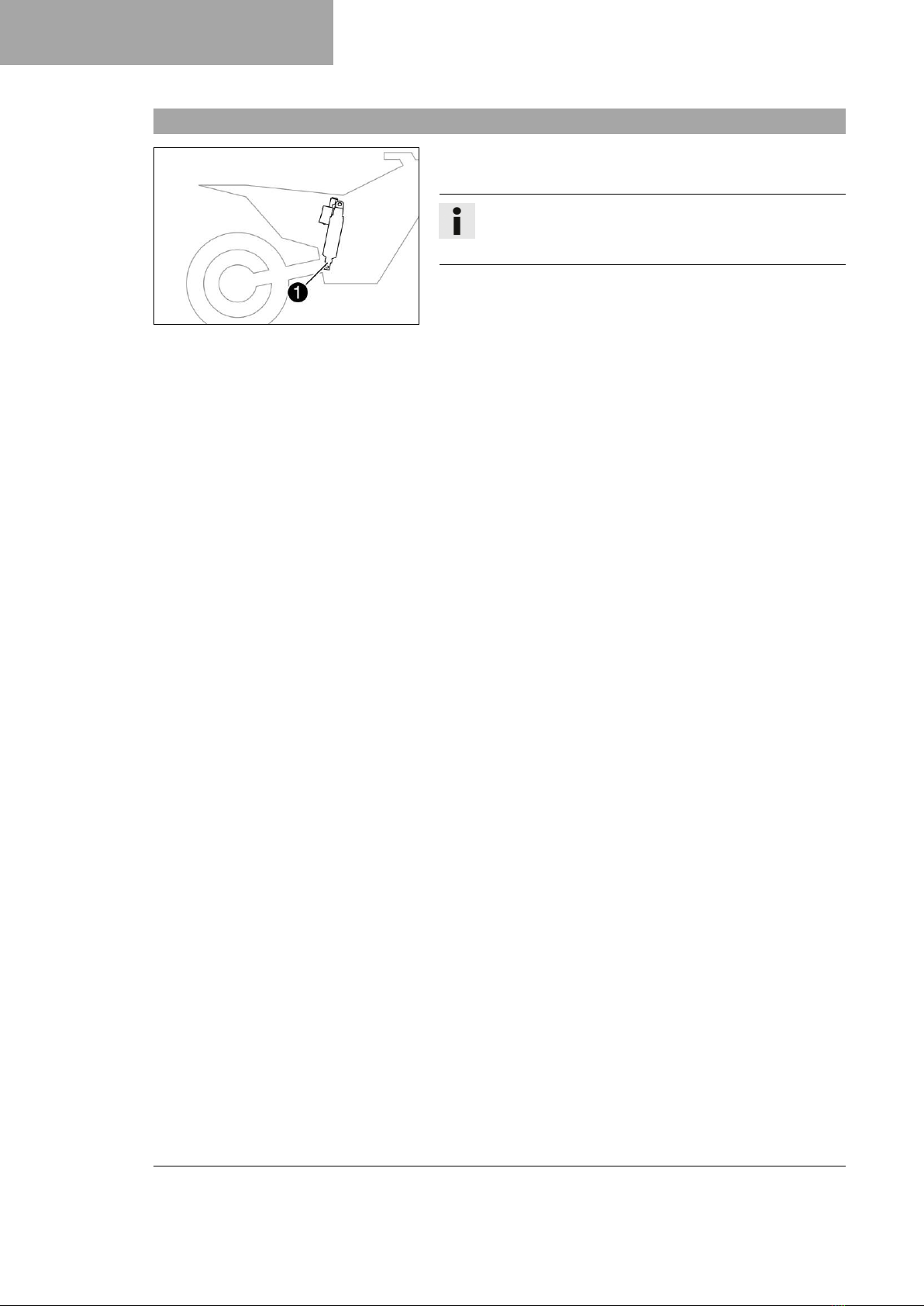
9.8 Measuring the rear wheel dimension
unloaded ............................................. 18
9.9 Checking the static sag of the
shock absorber ................................... 18
9.10 Checking the riding sag of the
shock absorber ................................... 19
9.11 Adjusting the spring preload of the
shock absorber ................................... 19
9.12 Adjusting the riding sag .................. 20
10 TECHNICAL DATA .......................................... 21
10.1 Shock absorber .................................. 21
11 SUBSTANCES................................................. 23
12 STANDARDS ................................................... 24
13 LIST OF ABBREVIATIONS .............................. 25
INDEX ...................................................................... 26