WPL GREASE GUZZLER User manual

1WPL/GG2O&M/0704/v5
OPERATION AND
MAINTENANCE MANUAL
FOR
GREASE GUZZLER®

2WPL/GG2O&M/0704/v5
OPERATION AND MAINTENANCE
OF GREASE GUZZLER®
LIQUID BIO-FLUID DOSING UNIT
INDEX
1: Health and Safety 3
2: Introduction 4
3: Customer Operating Instructions 4
APPENDIX I: Dosage setting 6
APPENDIX II: Rell Routine 7
APPENDIX III: Wiring Diagram 8
APPENDIX IV: Fault Finding 9
APPENDIX V: Changing Components 9
APPENDIX VI: Spares List 10
APPENDIX VII: Health and Safety Data Sheet-Bio-uid 11

3WPL/GG2O&M/0704/v5
1. HEALTH AND SAFETY
1.1. United Kingdom Health and Safety at Work Act 1974
Section 6a of this act requires manufacturers to advise their customers on the safety and the
handling precautions to be observed when operating, maintaining and servicing their products.
The user’s attention is drawn to the following:
All the sections of this manual must be read before working on the equipment.
See bio-uid Health & Safety Data Sheets
Only suitably trained and qualied personnel must carry out installation.
Normal safety precautions must be taken and appropriate procedures observed to avoid
accidents.
Refer to WPL Ltd for any technical advice or product information.
1.2. Health
Hazards Identication
Excessive ingestion of the bio-uid may cause nausea or diarrhoea.
May be an irritant to skin and eyes.
First Aid Measures
Skin contact: Wash off with plenty of water.
Eye contact: Wash immediately with copious quantity of water.
Ingestion: Rinse mouth and throat and drink water to dilute.
Inhalation: Not applicable.
If symptoms persist seek medical advice.
1.3. Safety
Important Safety Notice
The Grease Guzzler®is only to be opened by trained personnel.
Before carrying out any maintenance work, the equipment must be electrically isolated.
Ensure that the Grease Guzzler®has its front panel closed and locked, with its operating key
removed when unattended, to prevent access by unauthorised personnel.
Ensure that the bio-uid is handled under good housekeeping practices. Wash hands after
use; wear gloves if exposure is prolonged. Care should be taken to ensure the product is not
introduced to drinking water or foodstuffs. Store in a dry and cool place. See Appendix VII
for Health and Safety Data Sheet.

4WPL/GG2O&M/0704/v5
2. INTRODUCTION
CAUTION
When installing the Grease Guzzler® into an established kitchen, there may be an existing build-up of
grease within the drain line. Upon installation, the bio-uid will begin to degrade the grease, potentially
causing it to break away from the pipes in large clumps, which may lead to a blockage. WPL advise that
the drain system be pressure washed at the time of installation if there are signs of a grease build up
The Grease Guzzler®is designed to keep drains and grease traps free from build up of fats and greases,
eliminating or reducing blockages and the need for manual cleaning.
Grease Guzzler® is fully automatic and, once set up, regulates the amount of biouid into the system at
pre-set intervals during periods of low ow through the drainage system. It ensures that fat and grease
build up is kept to a minimum and eliminates or reduces the need for the grease traps to be cleaned out
manually.
Pre heating the biouid to its optimum temperature enables it to pre activate and multiply prior to
discharge to the drainage system, thus speeding up the rate at which the grease is broken down.
Grease Guzzler®is suitable for use in the following situations: Restaurants and fast food outlets, hotels,
school/ofce/factory canteens or any establishment with canteen facilities.
Grease Guzzler®Operation
Automatic dosing operation
Manual override via test button
Safety Features
Integral Fuse
Reset push button
Weight - NO FLUID 20kg
Weight - WITH FLUID 25kg
Weight - inlcuding full incubation tank and uid 28kg
System Requirements
220 ~ 240v, Single phase, 5amp (fused spur)
Cold water supply
Discharge point to drain
Internal wall mounting
Annual Service & Cleaning Hints (See also 4.6)
From experience in the eld, Service Engineers will need approximately 10 minutes to complete the tasks listed
below.
i. Turn power off
ii. Turn water supply off
iii. Visually check the bio-product feed pump and piping for residual solids
iv. Generally clean inside and out with damp cloth
v. Reassemble and test
vi. Turn power and water on

5WPL/GG2O&M/0704/v5
3. CUSTOMERS OPERATION MANUAL FOR GREASE GUZZLER®
The operation of the WPL Grease Guzzler®is fully automatic and only requires minimal user maintenance
once your supplier has commissioned the unit (Item 5, Installation Manual). Your maintenance contract is
with your supplier at an agreed interval.
The Grease Guzzler® regulates the dosing of a solution, known as biouid, containing active bacteria and
enzymes into your drain lines at a set time each day, normally when the kitchen has closed for the night or
at a pre-determined quiet period. This active solution will assist in keeping the drain lines free from build
up of fats, grease and oils. The complete cycle is pre-set for a period normally between two and ve hours
during which time the solution is held at 38-400C to activate the bacteria.
You can monitor the automatic operation using a series of indicator lights provided on the front panel. All
lights have a description adjacent, a full explanation of the purpose follows:-
Bio-Fluid Low/Call Engineer indicates when biouid supply is low, contact service engineer.
Power On Indicates the electrical supply is live
Heater On Indicates the activity of the heater
4. SEQUENCE OF OPERATION: -
At all times the POWER ON should be illuminated. During the operating cycle the following sequence
can be observed:
‘On Lamp’ on – heating on lamp will go off when the water is at the required temperature and will then
periodically come on to maintain the desired temperature.
4.1. Operating Instructions
Important Safety Notice
Only a qualied technician may open the Grease Guzzler®. Before opening the door, isolate the
machine from the mains electricity supply. Ensure that the Grease Guzzler®has its door shut and
locked, with its operating key removed, when unattended to prevent access by unauthorised personnel.
4.2. Setting up of daily dosage
Please refer to Appendix I for details of how to set up multi-dosing. The unit is pre-set to one dose per
day.
Ensure that there is power supplied to the Grease Guzzler®(Power on indicator illuminated)
Ensure that there is an adequate water supply to the Grease Guzzler® so that the tank lls in a
MINIMUM of one (1) minute.
4.3. For test operation of the Grease Guzzler®
Press the red push-button for a count of ten seconds and the test run will automatically come into
operation. All lights will come on, bacteria feed pump will operate and the heater pad will come on.
This can be checked through the specically designed aperture.
4.4. Capacities and consumption rates (Approximate)
Bio-uid bag capacity = Six months supply at one dose per day
Mixing tank capacity = 2.5 litres (Liquid capacity/dispense rate/cycle at 35 to 40 C)
Dosing rate = Up to 4 cycles per day, with a minimum of 6 hours between dosing.
Bio-uid consumption = 25 ml per cycle
4.5. Dimensions: Enclosure (width x height x depth) = 530 x 560 x 200 mm
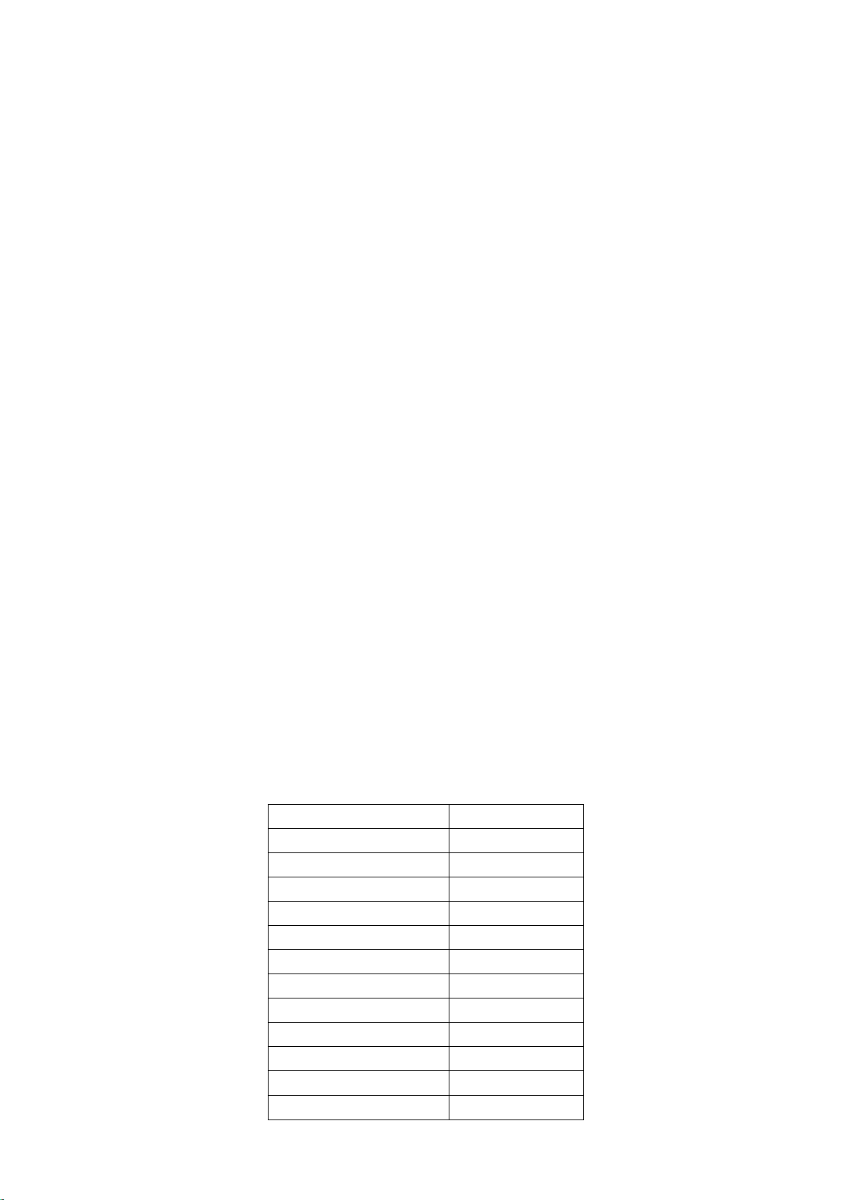
Check Method Interval
Bio-Fluid level Bio-Fluid warning light Weekly
Function
Check
Press/ick the test button/switch for 10 seconds and observe the test
cycle. Six monthly
Cleanliness Wash down the outside of the machine to remove any spillage and dirt
build up. Weekly
De-scaling and
Cleaning
Add a de-scaling solution to boiling water and pour into the incubation tank.
Leave the solution in the tank for ve minutes and run the test cycle once.
Once de-scaling is complete, continue to use as normal.
Annual

6WPL/GG2O&M/0704/v5
4.6 Maintenance routine
The following checks to be carried out at the intervals shown below.
APPENDIX I Daily Dosing Settings
The Grease Guzzler®will normally leave the factory with the switches in the default position, i.e. once
per day.
Follow the drawing below to amend any dosing schedule. Wiring is shown as default, one dose per day.
Adjust the wiring to the dosing regime required. Refer to Health and Safety section (page 3) before
making any amendments.
• • • •
PCB
One Per Day Two Per Day Three Per Day Four Per Day
Red Wire


7WPL/GG2O&M/0704/v5
APPENDIX II Filling Routine
Rell Period
The period between rells for the bio-uid is dependent upon the number of cycles run during the day.
For installations where there is a considerable amount of fats and greases discharged to the waste water
system, it may be necessary to run up to four cycles per day. For light fat and grease discharge, once a
day may be sufcient. The times shown are as a guide only and the discharge should be set to coincide
with periods of zero or low ow through the drainage network. to maximise biouid efffeciveness The
system is factory pre-set for one daily dosing to the drains.
Relling Regime On Off On Off On Off On Off
The unit doses the drain system at the following times, during this time
the dose valve will open for six (6) seconds
In once per day mode 00.30
In twice per day mode 00.30 09.00
In thrice per day mode 00.30 08.00 16.00
In four per day mode 00.00 06.00 12.00 18.00
Relling Regime On Off On Off On Off On Off
The feed pump will feed 25 ml of bio-uid to the mixing tank at the
following times
In once per day mode 16.30
In twice per day mode 16.30 01.00
In thrice per day mode 16.01 00.01 08.01
In four per day mode 18.01 00.01 06.01 12.01
Relling Regime On Off On Off On Off On Off
The heating mat cycles on and off during the following times
In once per day mode 16.30 00.30
In twice per day mode 16.30 00.30 01.00 09.00
In thrice per day mode 16.01 00.30 00.01 08.00 08.01 16.00
In four per day mode 18.01 00.00 00.01 06.00 06.01 12.00 12.01 18.00
System Layout

9WPL/GG2O&M/0704/v5
APPENDIX IV Fault Finding
For details of how to remove any component see Appendix VI. Consumable can be ordered through your
local Grease Guzzler Supplier. Alternatively, you can contact WPL Limited directly.
Chart No.1 Electrical Faults
Symptom Cause Cure
No power or intermittent
power to all or any circuit Supply fault to unit Check fuse in RCD spur
No lamps, including ‘Power
On’ illuminated Mains fuse or poor connection 1.Checkfuse& bothlineandneutral continuity
2. Check internal fuse
‘Heater On’ not illuminated The unit may be at temperature or not in
heating cycle To check run test cycle
Chart No.2 - Mechanical and Electro-mechanical faults
Symptom Cause Cure
No Bio uid used Faulty pump Check operation with test run
Dosing tank does not heat up Faulty electrical connections or heater Return to factory, t new heater pad
Dosing tank does not empty 1. Solenoid faulty 1. Check operation with test run
2. Return to factory, t new solenoid
2. Blocked drain line prevents discharge 3. Clear drain line
Dosing tank does not ll or
overows
1. Fill valve faulty
2. No mains water or very low pressure
1. Check water supply or change the valve.
2. Check the water supply

10WPL/GG2O&M/0704/v5
APPENDIX V Changing Components
Important: Electrical and water supply must be isolated from the unit before any work is carried out. It is
recommended that only ONE component be changed at a time, with a test on function between
each change. Supply must be isolated at each stage before any further work is carried out.
Before removing any suspect component it is advisable to check that there are no faults in the control
system or the supply, both electrical and water, to the item in question. See Appendix V for fault location.
7. Bio-product Feed Pump
i. This operation serves a dual purpose in removing the pump and carrying out an in
situ service
ii. Undo pump bracket from machine chassis by undoing two M5 Nylok nuts
iii. Remove the two cross-headed screws from the front of the pump and remove cover
iv. Unclip the black spring clip on the back of the motor. Using a at-headed screwdriver
gently prise the motor off.
v. With the motor removed two more cross-headed screws will need to be taken out
in order to remove the pump itself. Again, this will need to be gently prised away
with a screwdriver.
vi. Fit new pump in the reverse order to removal.
vii. Re-connect supplies and test.
8. Flush Solenoid
i. Disconnect electrical leads.
ii. Release both sides of the valve by unscrewing the gland nuts. Also release the ‘T’
piece at the outlet from the mixing tank to allow the pipes to be withdrawn from the
valve
iii. TAKE CARE NOT TO DAMAGE THE RIBBON .
iv. Remove the solenoid.
v. Fit new solenoid in the reverse order to removal.
vi. Re-connect supplies and test.
APPENDIX VI Spares List
Description Part Number
Heater mat 50-020-350
Membrane display 50-050-005
Ribbon connectors 50-050-006
Water valve solenoid 29-101-900
PCB assembly DD-620-039
Controller 53-020-010
Push button RED 50-020-621
Push button WHITE 50-020-620
Connector bio-white DD-620-028
Seal, door 80-100-050
Valve Flush 25-990-020
Valve Float Bottom 25-990-010

11WPL/GG2O&M/0704/v5
Health and Safety Data Sheet Sheet 1 of 2
1 Commercial Product Name Supplier S65 (For use only in WPL Grease Guzzler®)
WPL Ltd.
Units 1 & 2 Aston Road, Waterlooville, Hampshire. PO7 7UX.
Tel. 02392 242600 Fax. 02392 242624
2 Composition Naturally occurring soil biocatalyst, proprietary organic biodegradable materials and
nutrients. This product, S65, belongs to the Fluid Category 4 according to Statutory
Instrument 1999 No. 1148 The Water Supply (Water Fittings) Regulations 1999.
3 Hazards Identication Dermal exposure may cause mild irritation of skin. Avoid contact. Moderately
irritating to the eyes
4 First Aid Measures Skin contact: Wash with soap and water. If irritation persists consult doctor
Eye contact: Flush with clean water for at least 15 minutes. If irritation develops
seek attention.
Ingestion: Do not induce vomiting, get medical help
Inhalation: Remove to fresh air, get medical help
If symptoms persist seek medical advice
5 Fire Fighting Extinguishing media: Use appropriate media for underlying cause of re
Hazardous combustion gases: None
6 Accidental Release After spillage/leakage: Sweep up and recover or mix with absorbent and shovel into an
appropriate container for disposal. Wash spilled area with disinfectant. Dispose of in
accordance with local and state regulations.
Cleaning of equipment: Wash with plenty of water
7 Handling/Storage All materials should be handled under good housekeeping practices:
wash hands after use; wear gloves if exposure is prolonged.
Care should be taken to ensure product is not introduced to drinking water or foodstuffs.
Store in a dry and cool place, within temperature range 5-35 deg. C. Avoid direct
sunlight. Keep away from strong oxidisers, strong acid, alkali and organic solvents.
8 Exposure Controls Respiratory protection: Approved dust mask as required
Personal Hand protection: Gloves recommended
Protection Eye protection: Recommended when handling large
quantities
9 Physical/Chemical Appearance: Liquid
Properties Colour Brown
Odour Characteristic
pH: 6-7.5
Boiling point: 100oC
Melting point: Not applicable
Flash Point Not Applicable
Ignition Point No data
Explosion limits No data
Density (Kg/dm3) 1.02
Vapour pressure
Viscosity
Solubility in water 99.5%
Partition coefcient in n-octanol/water

12WPL/GG2O&M/0704/v5
Health and Safety Data Sheet Sheet 2 of 2
10 Stability and Material is stable under normal conditions of use
Reactivity Known hazardous reactions: None
Hazardous decomposition products: None
11 Toxicological Toxicity: No acute toxicity
Information Pathogenicity: Component bacteria are non-pathogenic and
generally regarded as safe
Carcinogenicity: No known carcinogens
LD50 acute oral No
12 Ecological Product believed not to be dangerous to the environment with
Information respect to mobility, persistency and degradability, bioaccumulative
potential, aquatic toxicity and other data relating to ecotoxicity
13 Disposal Disposal should be in accordance with local authority regulations
considerations
14 Transport Regulations Class UN-Nr PGr
RID/ADR not classied
ICAO/IATA-DGR not classied
GGVSee/IMDG-Code: not classied
15 Regulatory Label name: S65
Information Symbols: None
Risk phrases: None
Safety phrases: Keep away from children.
Labelling according to EC directives.
16 Other Product should be stored, handled and used in accordance with good industrial hygiene
practices and in conformity with legal regulations. The information contained herein is
based on the present state of our knowledge and is intended to describe our products
from the point of view of safety requirements. It should therefore not be construed as
guaranteeing specic properties. All information contained within this Health and Safety
Data Sheet is believed to be true and correct as at date of issue. However, the accuracy
and completeness of the information and any recommendations or suggestions are made
without warranty or guarantee. As conditions of use are beyond the control of WPL,
responsibility for safe use lies with the user.
Table of contents