WTC WTC 200 User manual


2
SEPTEMBER 2020

3
CONTENTS
1. GENERAL INFORMATION................................................................................................................................ 5
2. PRECAUTIONS..................................................................................................................................................5
2.1. Operation.....................................................................................................................................................5
2.2. Battery Power Supply..................................................................................................................................5
3. WARRANTY CONDITIONS ...............................................................................................................................6
4. DESIGN ..............................................................................................................................................................6
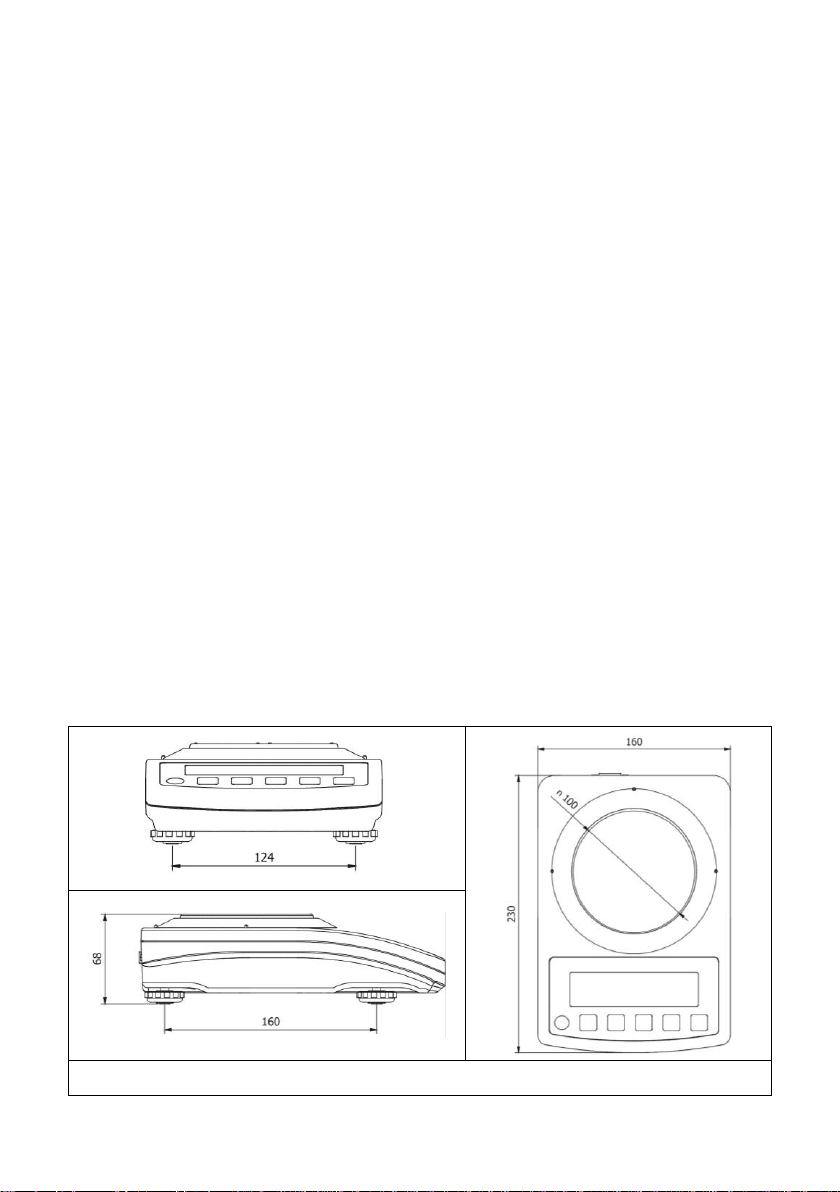
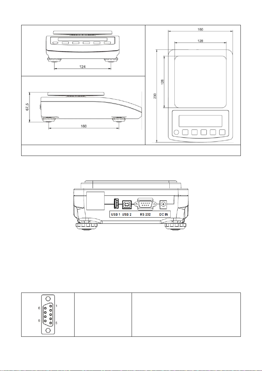
4.1. Dimensions..................................................................................................................................................6
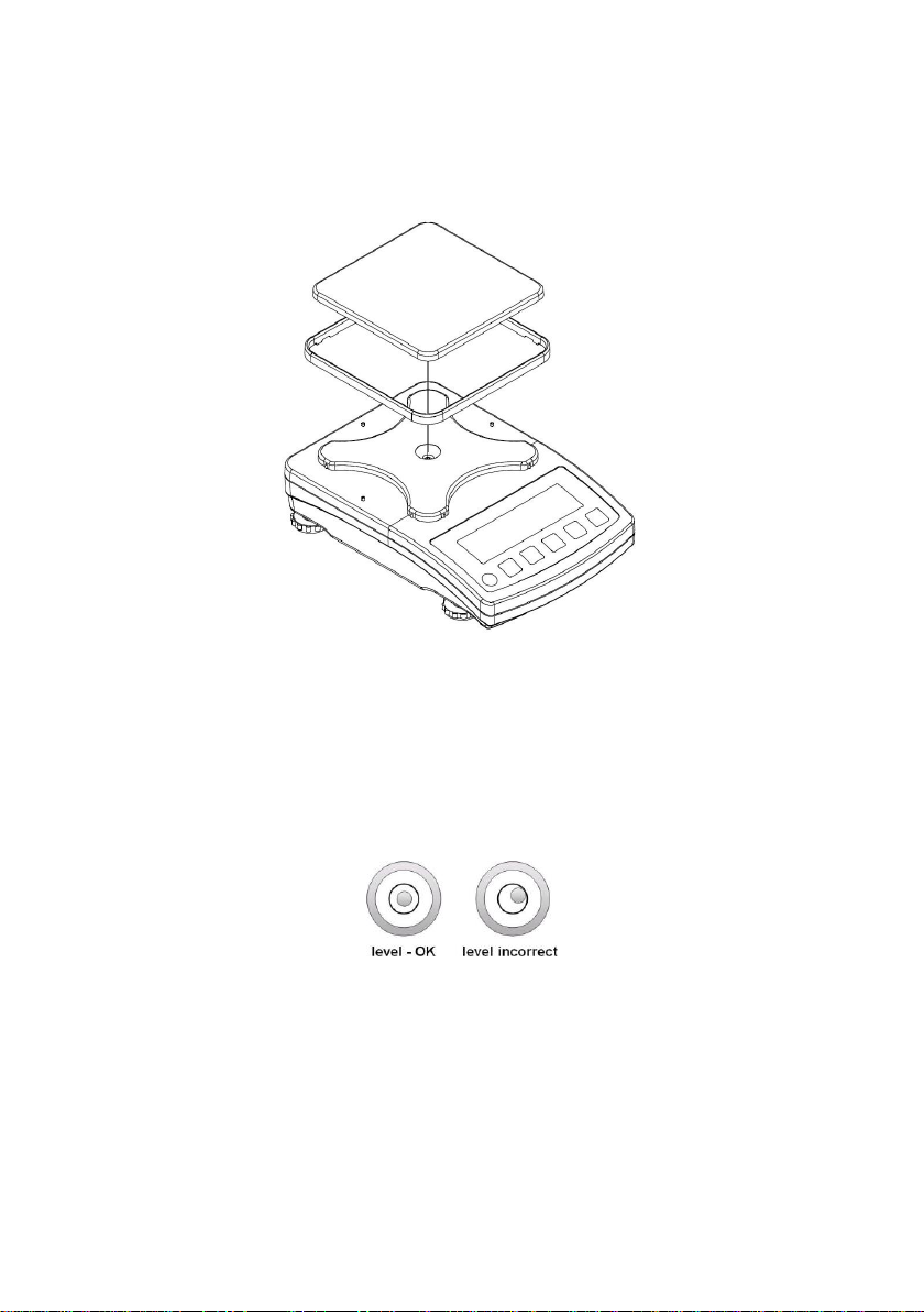
4.2. Connectors Arrangement ............................................................................................................................7
4.3. Connectors Description...............................................................................................................................7
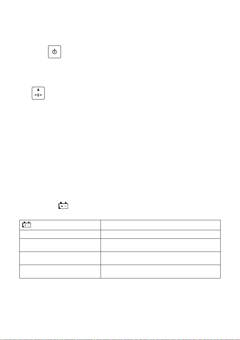
5. UNPACKING AND INSTALLATION..................................................................................................................8
6. START-UP AND OPERATION ..........................................................................................................................8
6.1. Levelling.......................................................................................................................................................8
6.2. Connecting the Scale to the Mains .............................................................................................................8
6.3. Warm-Up Time............................................................................................................................................9
6.4. Battery Charge Status.................................................................................................................................9
6.5. Battery Charge Status Check....................................................................................................................10
7. MAINTENANCE ACTIVITIES .......................................................................................................................... 10
7.1. Cleaning ABS Components.......................................................................................................................10
7.2. Cleaning Stainless Steel Components......................................................................................................10
8. OPERATION PANEL .......................................................................................................................................11
9. KEYS................................................................................................................................................................. 11
10. PROGRAM STRUCTURE..............................................................................................................................12
10.1. Function Groups......................................................................................................................................12
10.2. Operating the Menu.................................................................................................................................12
10.3. Return to the Weighing Mode .................................................................................................................13
11. WEIGHING OPERATION...............................................................................................................................13
11.1. Good Weighing Practice..........................................................................................................................13
11.2. Zeroing ....................................................................................................................................................14
11.3. Taring ......................................................................................................................................................14
11.4. Entering Tare Value Manually.................................................................................................................14
11.5. Dual Range Devices................................................................................................................................15
11.6. Units.........................................................................................................................................................15
11.6.1. Start Unit ......................................................................................................................................15
11.6.2. Temporary Unit.............................................................................................................................16
12. ADJUSTMENT ............................................................................................................................................... 16
12.1. External Adjustment................................................................................................................................17
12.2. User Adjustment......................................................................................................................................17
12.3. Adjustment Report...................................................................................................................................18
13. SCALE PARAMETERS .................................................................................................................................18
13.1. Filter.........................................................................................................................................................18
13.2. Value Release.........................................................................................................................................19
13.3. Ambient Conditions .................................................................................................................................19
13.4. Autozero Function ...................................................................................................................................19
13.5. Tare Function ..........................................................................................................................................20
13.6. Tare: Enter Mode ....................................................................................................................................20
13.7. Tare: Values Memory..............................................................................................................................21
13.7.1. Entering Tare Value to the Weighing Device Memory.................................................................21
13.7.2. Selecting Tare Value from the Weighing Device Memory...........................................................21
13.8. Last Digit..................................................................................................................................................22
14. COMMUNICATION ........................................................................................................................................22
14.1. RS232 Port..............................................................................................................................................22
14.2. USB A Port..............................................................................................................................................23
14.3. USB B Port..............................................................................................................................................23
14.4. Wireless communication module ............................................................................................................25
15. PERIPHERAL DEVICES................................................................................................................................26
15.1. Computer.................................................................................................................................................26
15.1.1. Computer Port..............................................................................................................................27
15.1.2. Continuous Transmission.............................................................................................................27
15.1.3. Printout Interval for Continuous Transmission.............................................................................27
15.2. Printer......................................................................................................................................................27
15.2.1. Printer Port...................................................................................................................................27

4
15.3. Additional Display....................................................................................................................................28
15.3.1. Additional Display Port.................................................................................................................28
16. PRINTOUTS ...................................................................................................................................................28
16.1. Adjustment Report...................................................................................................................................28
16.2. GLP Printout............................................................................................................................................29
17. MISCELLANEOUS PARAMETERS ..............................................................................................................30
17.1. Automatic Backlight Switch-Off...............................................................................................................30
17.2. Display Brightness...................................................................................................................................30
17.3. 'Beep' Sound ...........................................................................................................................................31
17.4. Automatic Shutdown ...............................................................................................................................31
17.5. Date and Time.........................................................................................................................................32
17.6. Default User Settings ..............................................................................................................................32
18. SCALE DATA................................................................................................................................................. 32
19. WORKING MODES –General Information .................................................................................................33
19.1. Running Working Mode...........................................................................................................................33
19.2. Working Modes Local Settings................................................................................................................33
19.2.1. Working Mode Accessibility .........................................................................................................34
19.2.2. Save Mode ...................................................................................................................................34
19.2.3. Automatic Printout Time Interval..................................................................................................34
19.2.4. Lo Threshold................................................................................................................................35
20. WORKING MODE –WEIGHING ................................................................................................................... 35
20.1. Local Settings..........................................................................................................................................35
21. WORKING MODE –PARTS COUNTING ..................................................................................................... 35
21.1. Local Settings..........................................................................................................................................36
21.1.1. Selecting Operation Mode............................................................................................................36
21.2. Setting Sample Mass by Entering Mass of a Single Part .......................................................................36
21.3. Setting Sample Mass by Determining Mass of a Single Part .................................................................37
22. WORKING MODE –+/- CONTROL............................................................................................................... 37
22.1. Local Settings..........................................................................................................................................38
22.2. Declaring Checkweighing Thresholds.....................................................................................................38
23. WORKING MODE - PERCENT WEIGHING..................................................................................................38
23.1. Local Settings..........................................................................................................................................39
23.1.1. Selecting Operation Mode............................................................................................................39
23.2. Reference Sample Mass Determined by Weighing................................................................................39
23.3. Reference Sample Mass Determined by Entering the Mass Value .......................................................39
24. WORKING MODE –PEAK HOLD.................................................................................................................40
24.1. Local Settings..........................................................................................................................................40
24.2. Peak Hold Operation...............................................................................................................................40
25. WORKING MODE –TOTALIZING ................................................................................................................40
25.1. Local Settings..........................................................................................................................................41
25.2. Totalizing Operation................................................................................................................................41
26. WORKING MODE –ANIMAL WEIGHING ....................................................................................................42
26.1. Local Settings..........................................................................................................................................42
26.2. Animal Weighing Operation ....................................................................................................................42
27. IMPORT / EXPORT........................................................................................................................................43
27.1. Weighing Records Export .......................................................................................................................43
27.2. ALIBI Weighings Export .......................................................................................................................... 43
27.3. Parameters Export / Import .....................................................................................................................44
28. DIAGRAMS OF CONNECTION CABLES.....................................................................................................44
29. TECHNICAL SPECIFICATIONS....................................................................................................................45
30. TROUBLESHOOTING ................................................................................................................................... 45
31. ERROR MESSAGES .....................................................................................................................................46

5
1.GENERAL INFORMATION
WTC precision scale enables fast and accurate mass measurements under
laboratory conditions. The weighing pan, made of stainless steel and equipped
with an anti-draft shield, is an integral part of the WTC scale. Due to a backlit
LCD display the measurement result is clearly visible. The scale is equipped
with an internal battery which allows its operation in places where there
is no access to the mains.
WTC scale is equipped with the following interfaces: RS 232, USB type A, USB
type B, wireless communication (option). The interfaces enable cooperation
between the scale and peripheral devices (e.g. printer, computer, flash drive).
2.PRECAUTIONS
2.1. Operation
A. Prior the first use, carefully read this User Manual. Use the device only
as intended.
B. Scales to be decommissioned must be decommissioned in accordance
with valid legal regulations.
2.2. Battery Power Supply
WTC scales are intended to be supplied by NiMH battery (nickel metal hydride)
of 1800 - 2800 mAh capacity.
Do not let battery discharge in case of prolonged storage
of the device in low temperature.
Accumulators do not belong to regular household waste.
The European legislation requires discharged accumulators
to be collected and disposed separately from other
communal waste with the aim of being recycled. Dear user,
you are obliged to dispose of the worn out batteries
as regulated.
A worn out battery can be replaced only by the manufacturer
or by the authorized service.
Notice: Symbols on batteries identify harmful compounds:
Pb = lead, Cd = cadmium, Hg = mercury.

6
3.WARRANTY CONDITIONS
A. RADWAG feels obliged to repair or exchange all elements that appear
to be faulty by production or by construction.
B. Defining defects of unclear origin and means of their elimination can only
be realized with assistance of manufacturer and user representatives.
C. RADWAG does not bear any responsibility for damage or losses
resulting from unauthorized or inadequate performing of production
or service processes.
D. The warranty does not cover:
mechanical damage caused by product exploitation other than
intended, damage of thermal and chemical origin, damage caused by
lightning, overvoltage in the power network or other random event,
inappropriate cleaning habits.
E. Loss of warranty takes place if:
a repair is carried out outside RADWAG authorized service point,
service claims intrusion into mechanical or electronic construction
by unauthorized people,
the device does not bear company security stickers.
F. Warranty conditions outline the warranty period for rechargeable
batteries attached to the device for 12 months.
G. For detailed warranty conditions read the warranty certificate.
H. Contact with the central authorized service: +48 (48) 386 63 30.
4. DESIGN
4.1. Dimensions
Figure 1. Dimensions of WTC 200 scale

7
Figure 2. Dimensions of WTC 600, WTC 2000, WTC 3000 scale
4.2. Connectors Arrangement
Figure 3. Connectors view
DC IN –power supply socket
RS232 - RS232 connector
USB 2 - USB „device” connector
USB 1 - USB „host” connector
4.3. Connectors Description
Pin2 –RxD
Pin3 –TxD
Pin4 –5VDC
Pin5 –GND
RS 232 connector DB9/M (male)

8
5.UNPACKING AND INSTALLATION
Unpack the device and place it on a flat and even surface. Keep it far
away from any sources of heat.
Install the weighing pan and the draft shield, follow figure 4.
Figure 4. Scale assembly
6.START-UP AND OPERATION
6.1. Levelling
To level the weighing instrument turn its feet. Keep turning the feet until the air
bubble takes central position:
6.2. Connecting the Scale to the Mains
The weighing device can be connected to the mains only with a power supply
that comes standard with the particular model. Nominal voltage of the power
supply (specified on the power supply data plate) has to be compatible with
the mains nominal voltage.

9
Procedure:
Connect the power supply to the mains. Plug it to the power supply socket
(back side of the scale housing).
Press key. The key is also used to switch the scale on/off.
Display test proceeds (all symbols are backlit for a moment), program
name and number is displayed first, ZERO indication with reading unit
next (displayed reading unit is conditioned by scale type).
In case the weighing result is not zero after indication stabilisation, press
key.
6.3. Warm-Up Time
For correct scale operation, the workroom temperature must range
between +15C +30C.
It takes 30 minutes for the device to warm up.
During the thermal stabilization, the indications on the screen can change.
If you want to carry out adjustment operation, make sure that your device
is thermally stable.
Temperature and humidity variations during operation may cause
indication errors. To remove the indication errors perform user adjustment.
6.4. Battery Charge Status
The scale of standard design is equipped with an internal battery. Battery state
is signalled by pictogram, the pictogram is displayed in the top bar of the
display.
pictogram display mode
Meaning
No pictogram
Battery charged. Regular scale operation.
Pictogram displayed continuously
Too low battery charge (the scale is about to shut
down). Charge the battery immediately.
Blinking pictogram, blink frequency:
ca. 1 s
Battery charge in progress. The device is connected
to the power supply charging the battery.
Blinking pictogram, blink frequency:
ca. 0.5 s
Battery error. Battery is damaged.

10
6.5. Battery Charge Status Check
Press and keys combination.
Depending on the battery state, a respective status is displayed on the
screen for 2s:
80%
Battery power supply. Battery power given in %.
CHArGE
Battery charge in progress. The device is connected to the power supply
charging the battery.
-Err5-
Battery error. Battery is damaged.
Next, the home screen is displayed automatically.
7.MAINTENANCE ACTIVITIES
In order to ensure safety in the course of cleaning, it is necessary to disconnect
the device from the mains. With this condition met, uninstall the weighing pan
and other detachable components.
Cleaning the weighing pan while still installed may cause
damage of the measuring system.
7.1. Cleaning ABS Components
To clean dry surfaces and avoid smudging, use clean non-colouring cloths
made of cellulose or cotton. You can use a solution of water and detergent
(soap, dishwashing detergent, glass cleaner). Gently rub the cleaned surface
and let it dry. Repeat cleaning process if needed.
In the case of hard to remove contamination, e.g. residues of adhesive, rubber,
resin, polyurethane foam etc., you can use a special cleaning agents based on
a mixture of aliphatic hydrocarbons that do not dissolve plastics. Before using
the cleanser for all surfaces we recommend carrying out tests. Do not use
cleansers containing abrasive substances.
7.2. Cleaning Stainless Steel Components
Avoid using cleansers containing any corrosive chemicals, e.g. bleach
(including chlorine). Do not use cleansers containing abrasive substances.
Always remove the dirt using microfiber cloth to avoid damage of protective
coating.

11
In case of a daily maintenance:
1. Remove the dirt using cloth dipped in warm water.
2. For best results, add a little bit of dishwashing detergent.
8.OPERATION PANEL
Figure 5. Operation panel of WTC series scales
9.KEYS
Press to switch the weighing device on/off –hold the key for about 1
second.
Function key, press to change the working mode.
Press to send the weighing result to a printer or computer.
Press to zero the scale.
Press to tare the scale.
Upon pressing + keys combination, functions
of given keys change. Detailed information concerning use
of + keys combination is to be found further down
this manual.

12
10. PROGRAM STRUCTURE
Program menu is divided into function groups. Function group is a group
of interrelated parameters.
10.1. Function Groups
Function group
number
Function group
name
Description
P1
CAL
User Adjustment
P2
rEAd
Readout parameters
P3
Func
Working modes
P4
Conn
Communication
P5
ducE
Peripheral devices
P6
Prnt
Printouts
P7
Othr
Operation-related functions
P8
InFo
Scale data
P9
Unit
Units
IE
-
Import / Export
10.2. Operating the Menu
In order to navigate the program menu use the operation panel.
+
Press to enter the main menu.
+
Press to enter tare manually.
Press to enter tare from tare database.
Press to change value by 1 digit up.
Press to scroll the menu up.
+
Press to check battery/accumulator state.
+
Press to view date/time.
Press to scroll the menu down.
Press to change current parameter value.
Press to enter given submenu.
Press to modify given parameter.

13
Press to confirm modification.
Press to exit, function remains unmodified.
Press to move one menu level up.
10.3. Return to the Weighing Mode
Introduced menu modifications are automatically saved to scale memory upon
return to the home screen. To return to the home screen press key
repeatedly.
11. WEIGHING OPERATION
Load the weighing pan. Read the result when stability marker is displayed.
Only stable weighing results can be recorded (stability
marker ).
11.1. Good Weighing Practice
To assure long-term operation and correct mass measurements, follow
the rules presented below:
Load the weighing pan steadily
avoiding mechanical shocks.
Place weighed loads centrally on the
weighing pan (eccentricity errors are
specified by EN 45501 standard, point
3.6.2.).
Do not apply concentrated force (total
load in one point).

14
Avoid side loading, in particular side
shocks.
11.2. Zeroing
To zero mass indication press key. Zero indication and the following
pictograms are displayed: and . The instrument can be zeroed only
when the indication is stable.
Indication can be zeroed only within ±2% range of maximum
capacity. If the zeroed value is greater than ±2%
of the maximum capacity, then the software displays
message <Err2>, and short sound signal is heard.
11.3. Taring
To determine net weight value, load the weighing pan with a packaging, wait
for a stable indication and press key. Zero indication and the following
pictograms are displayed: Net and . The weighing device has been tarred.
Upon loading, net mass is displayed. Taring can be carried out repeatedly
within the whole weighing range. Remember not to exceed the maximum
capacity, i.e. sum of tare weight value and load weight value must be lower
than the maximum capacity value. Upon unloading the weighing pan, the sum
of tared masses with minus sign is displayed.
It is impossible to tare zero or negative values. When you
tare zero or negative values, message <Err3> is displayed,
short sound signal is heard.
11.4. Entering Tare Value Manually
Press and keys combination, tare value edit box is displayed.
Enter tare value, to do it press and keys:

15
Press to select digit that is to be edited.
Press to set digit value, 0 - 9.
Press key to confirm, the scale returns to the weighing mode,
modified tare value with '–'sign is displayed.
You can enter tare value at any time during the weighing operation.
11.5. Dual Range Devices
Switching from weighing with the accuracy of the I weighing range to weighing
with the accuracy of the II weighing range takes place automatically upon
exceeding Max of the I weighing range. Upon switching to weighing with the
accuracy of the II weighing range, respective pictogram/marker
is displayed in the top left hand corner.
To return to weighing with accuracy of the I weighing range:
Take the load off the weighing pan.
As the indication returns to zero and when symbols and are
displayed, press button.
II weighing range pictogram/marker gets blank, the scale returns
to weighings with the accuracy of the I weighing range.
11.6. Units
<P9.Unit> parameter group enables change of start unit and temporary unit.
Unit change can be performed in the course of weighing or during operation
of other modes. 'Parts counting' and 'Percent weighing' modes are exceptions.
11.6.1. Start Unit
Parameter for setting unit that is displayed and used after device start-up.
Procedure:
Enter <P9.Unit / 9.1.UnSt> submenu.
Press key, available units are displayed successively one by one.
Options in case when the main unit is [kg]: kg (kilogram), g (gram),
lb (pound)*, N (Newton).

16
*) –unit disabled for verified weighing devices.
Options in case when the main unit is [g]: g (gram), kg (kilogram), ct (carat),
lb (pound)*.
*) –unit disabled for verified weighing devices.
Select start unit and press key, next go back to the home screen,
to do it press key.
Upon next start-up the scale runs with set start unit.
11.6.2. Temporary Unit
Temporary unit runs from the moment it is set to the scale shut-down and
restart.
Procedure:
Enter <P9.Unit / 9.2.Unin> submenu.
Press key, available units are displayed successively one by one.
Options in case when the main unit is [kg]: kg (kilogram), g (gram),
lb (pound)*, N (Newton).
*) –unit disabled for verified weighing devices.
Options in case when the main unit is [g]: g (gram), kg (kilogram), ct (carat),
lb (pound)*.
*) –unit disabled for verified weighing devices.
Select temporary unit and press key, next go back to the home
screen.
12. ADJUSTMENT
option available for non-verified scales exclusively
In order to ensure the highest weighing accuracy, it is recommended
to periodically introduce corrective factor of indications to scale memory, the
said factor must be referred to a reference weight. This is so called adjustment.

17
Adjustment has to be carried out:
prior weighing,
if long breaks between successive measuring series occur,
if the ambient temperature has changed dynamically,
if the scale has been relocated.
Adjustment types:
external adjustment, <1.1.CA-E>, performed using an external weight
of declared mass, i.e. mass that cannot be modified,
user adjustment, <1.2.CA-u>, performed using an external weight of mass
of any value comprised within the weighing range, however not lower than
30% of the maximum capacity value.
12.1. External Adjustment
External adjustment must be carried out using an external adjustment weight
of class F1.
Procedure:
Enter <P1.CAL / 1.1.CA-E> submenu, text <UnLoAd> (remove weight)
is displayed.
Remove the load from the weighing pan and press key.
Mass of an empty weighing pan is determined, this is signalled with
display of 'dash', < ->. Next, text <LoAd> (load weight) and mass
value that is to be loaded, e.g. 200g (conditioned by scale type), are
displayed.
Load the weighing pan with weight of specified mass value and press
key.
Weight mass is determined, this is signalled with display of 'dash',
< - >. Next, text <UnLoAd> (remove weight) is displayed.
Remove the load form the weighing pan, <1.1.CA-E> submenu
is displayed.
12.2. User Adjustment
User adjustment must be carried out using an external adjustment weight
of class F1.

18
Procedure:
Enter <P1.CAL / 1.2.CA-u> submenu, edit box for declaring weight mass
is displayed (the mass value must be 30% of the maximum capacity
value).
Enter weight mass value and press key to confirm, text <UnLoAd>
(remove weight) is displayed.
Remove the load from the weighing pan and press key.
Mass of an empty weighing pan is determined, this is signalled with
display of 'dash', < ->. Next, text <LoAd> (load weight) and mass
value that is to be loaded, e.g. 100 g, are displayed.
Load the weighing pan with weight of specified mass value and press
key.
Weight mass is determined, this is signalled with display of 'dash',
< - >. Next, text <UnLoAd> (remove weight) is displayed.
Remove the load from the weighing pan, <1.2.CA-u> submenu
is displayed.
12.3. Adjustment Report
Adjustment report is automatically printed (using scale-connected printer) at the
end of each adjustment process. To declare report content go to <P6.1.CrEP>
submenu. For detailed information concerning report content read later
sections of this manual.
13. SCALE PARAMETERS
Scale parameters are set to adjust the weighing device to ambient conditions
(filters) or individual needs (autozero on/off, tare values memory). These
parameters are to be found in <P2.rEAd> submenu. <P2.rEAd> submenu
comprises functions allowing you to adjust your weighing device to ambient
conditions of given workstation.
13.1. Filter
Enter <P2.rEAd / 2.1.FiL> submenu.
Press key, filter values are displayed successively one by one:
1- Fast, 2- Average, 3–Slow.

19
Set respective value and press key to confirm, next go to the home
screen.
The higher filter value, the longer the weighing takes.
13.2. Value Release
Enter this parameter to adjust rate of stabilisation of the measurement result.
Depending on the selected option, weighing time is either shorter or longer.
Procedure:
Enter <P2.rEAd / 2.2.APPr> submenu.
Press key, available values are displayed successively one by one:
F_P - fast and reliable, PrEc –reliable, FASt –fast.
Press key to confirm, next go to the home screen.
13.3. Ambient Conditions
Parameter relating to ambient and environmental conditions of the workstation.
Enter this parameter and set 'nStAb' value if the ambient conditions are
unfavourable (air drafts, vibrations).
Procedure:
Enter <P2.rEAd / 2.3.Enut> submenu.
Press key, parameter values are displayed successively one by
one: nStAb –unstable, StAb –stable.
Press key to confirm, next go to the home screen.
13.4. Autozero Function
'Autozero' function has been designed to enable automatic control and
correction of zero indication. This guarantees precise weighing results.
There are, however, some cases when this function can be a disturbing factor
for the measuring process, e.g. very slow placing of a load on the weighing pan
(load adding, e.g. pouring, filling). In such case, it is recommended to disable
the function.

20
Procedure:
Enter <P2.rEAd / 2.4.Aut> submenu.
Press key, parameter values are displayed successively one by one:
YES –autozero function enabled, no –autozero function disabled.
Press key to confirm, next go to the home screen.
13.5. Tare Function
'Tare' function has been designed to enable setup of appropriate parameters
for tare operation.
Procedure:
Enter <P2.rEAd / 2.5.tArE> submenu.
Press key, available values are displayed successively one by one:
no
Regular tare mode. Select this parameter to make the scale overwrite
the set (selected) tare value with the most recently entered one.
tArF
Select this parameter to make the scale store the latest tare value
in memory. The latest tare value is displayed after scale restart.
AtAr
Automatic tare mode.
EAcH
Select this parameter to make the scale automatically tare each accepted
measurement.
Press key to confirm, next go to the home screen.
13.6. Tare: Enter Mode
The tare is entered using + keys combination from the home screen
level. There are two enter modes.
Procedure:
Enter <P2.rEAd / 2.6.ttr> submenu.
Press key, parameter values are displayed successively one by one:
This manual suits for next models
3
Table of contents
Other WTC Scale manuals