5220
SERIES
WALL
BOX
. .
. .
;
-
~---
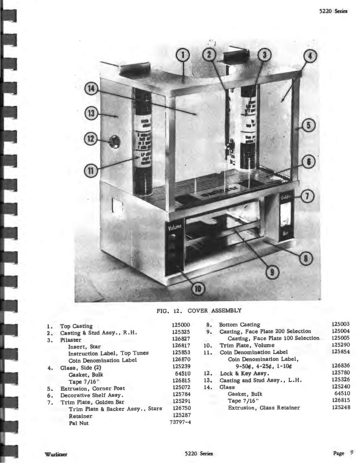
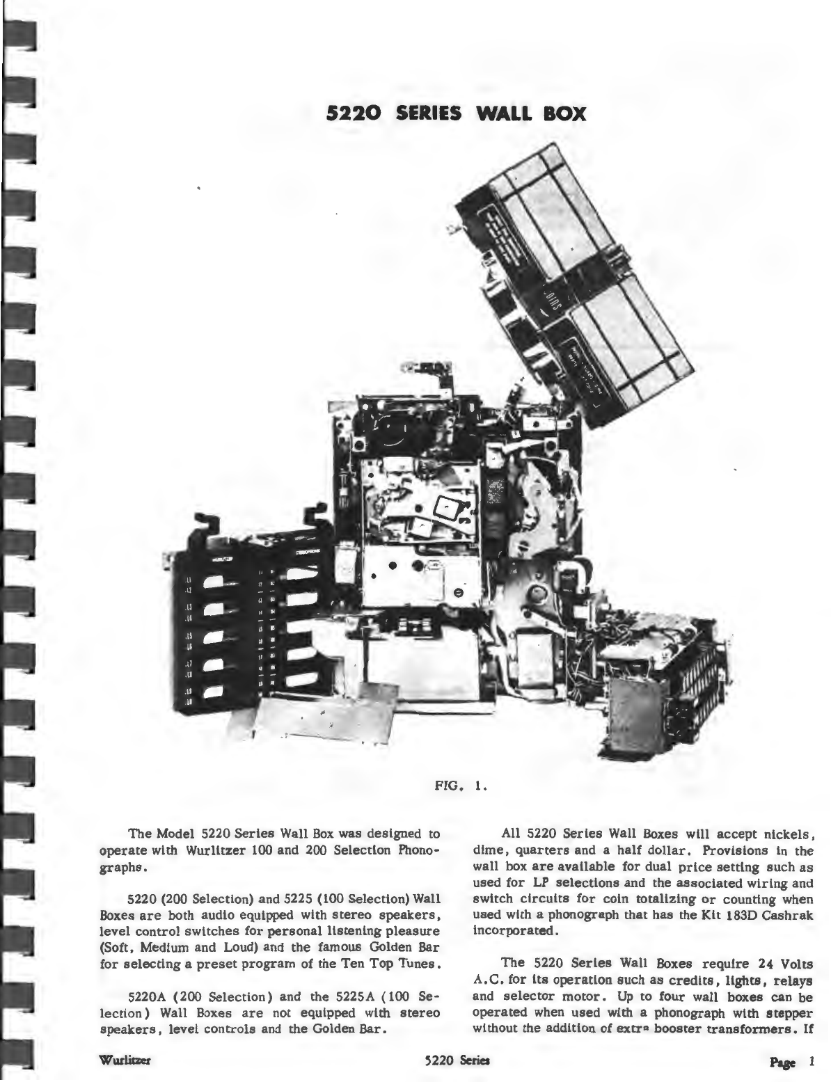
FIG.
1.
The
Model 5220
Series
Wall
Box
was
designed
to
operate
with
Wurlitzer
100 and 200 Selection Phono-
graphs.
5220 (200 Selection) and 5225 (100 Selection) Wall
Boxes
are
both audio equipped with
stereo
speakers,
level
control
switches
for
personal
listening
pleasure
(Soft, Medium and Loud) and
the
famous Golden Bar
for
selecting
a
preset
program
of the
Ten
Top
Tunes.
S220A (200
Selection)
and the 5225A ( 100
Se-
lection)
Wall Boxes
are
not equipped with
stereo
speakers,
level
controls
and the Golden
Bar.
All 5220
Series
Wall Boxes will
accept
nickels,
dime,
quarters
and a
half
dollar.
Provisions
in
the
wall box
are
available
for
dual
price
setting
such
as
used
for
LP
selections
and the
associated
wiring
and
switch
circuits
for
coin
totalizing
or
counting when
used
with a phonograph
that
has
the Kit 183D
Cashrak
incorporated.
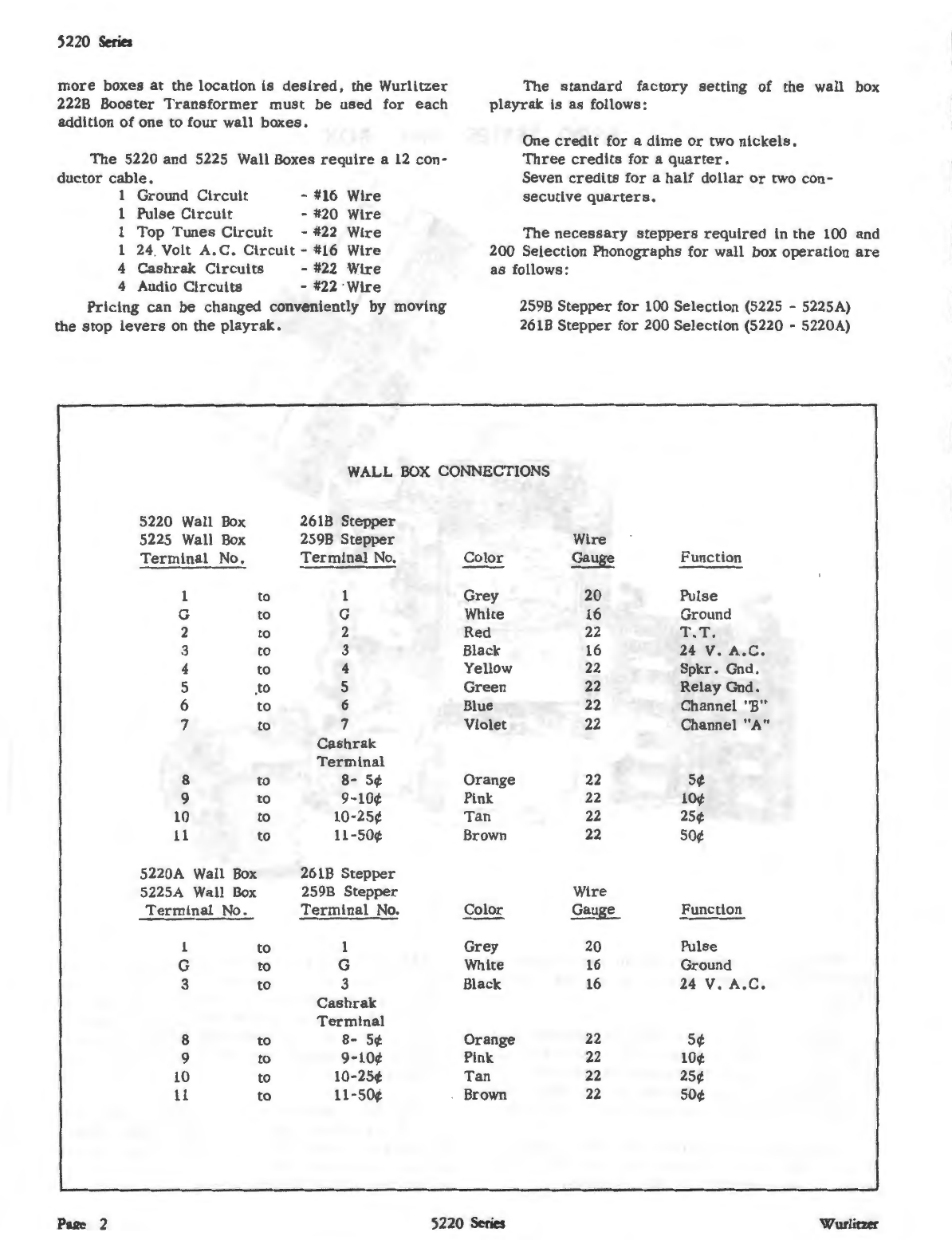
The
5220
Series
Wall Boxes
require
24 Volts
A.
C.
for
its
operation
such
as
credits,
lights,
relays
and
selector
motor.
Up
to
four
wall
boxes
can
be
operated
when
used
with a phonograph with
stepper
without the addition of
extr"
booster
transformers.
If
Wurliczer
5220
Series
Pase
1