WURM GTW-LAN User manual

GTW-LAN
Product information
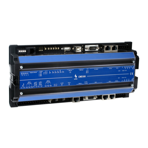
Front view
LAN gateway for remote data transfer
Features
Data interface to the systems with Wurm control
Identification of 4 Frigolink master modules
Real-time clock and synchronisation of the day/night function for the entire system
Fault forwarding of alarms to 2 different destinations
Handling of 2 FIO001B or FIO-PAT input/output modules for additional fault/operation inputs
and relays for provision of 4 alarm priorities
Two relays for central alarm of the overall system (Prio 1 and Prio 2) or for alternative functions
priority-free central alarm and router reset
Data memory for signal history
8 LEDs for status display
Temporary suppression of the fault report for work on the system using the Service key
Direct connection of a CAN USB to the service socket
Connection to the Wurm system via a communication bus (CAN bus) and Frigodata XP
GTW-LAN_PI_2015-02_EN Subject to technical changes Page 1 of 4

GTW-LAN
Product information
Writing conventions
Symbol
Meaning
CAUTION!
Avoid the described hazard: Otherwise minor or medium bodily injury or
property damage will result.
WARNING!
Avoid the described hazard: Otherwise there is danger from electric voltage
that can lead to death or serious bodily injury.
For your safety
For safe operation and to avoid personal injury and equipment damage through operational error,
always read these instructions, become familiar with the device, and implement all of the safety
instructions on the product and in these instructions as well as the safety guidelines of Wurm GmbH &
Co. KG Elektronische Systeme. Keep these instructions ready to hand for quick reference and pass
them on with the device when the product is sold.
Wurm GmbH & Co. KG Elektronische Systeme accepts no liability in case of improper use or use for
other than the intended purpose.
Target group
These service instructions are directed at "service technician" specialists.
Intended use
The GTW-LAN gateway is used for remote data transfer via a network. It
automatically relays alarms to max. 2 destinations.
WARNING! Danger of death from electric shock!
Switch off the power to the entire system when installing, wiring or removing! Otherwise a
mains voltage may still be present even if the control voltage is switched off!
The wiring of the device should be carried out only by a qualified electrician!
Use only the correct tools for all work!
Check all wiring after connection!
Never expose the device to moisture, for example due to condensation or cleaning agents!
Take the device out of operation if it is faulty or damaged and is therefore compromising
safe operation!
CAUTION!
Danger of fire if there is overloading of the relay contacts!
Ensure the maximum loads on all connections!
Faults are caused by electromagnetic interference!
Use only shielded data lines and place them far away from power lines!
Damage to device if handled incorrectly!
Do not open the device.
Do not repair the device yourself! If required, send it in for repair with an exact description
of the fault!
Software revisions and validity of documentation
Software version
Function expansion
Page
V1.0
2012-01
Base documentation
V2.0
2015-02
Updating of documentation
All software versions that are not listed are special solutions for individual projects and are not documented in this description in
detail. The validity of this document automatically expires upon publication of a new technical description. Manufacturer: Wurm
GmbH & Co. KG Elektronische Systeme. For further information, see our website at www.wurm.de
Page 2 of 4 Subject to technical changes GTW-LAN_PI_2015-02_EN

GTW-LAN
Product information
Circuit diagram
Mount
WARNING! Danger of death from electric shock!
Switch power off to the entire system when installing! Otherwise, external voltage
can be present even when control voltage is shut off.
The device has been designed for profile rail mounting. The housing is a standard size and is also
suitable for installation in fuse boxes. It can be positioned immediately next to another without gaps.
First, place the upper guide edge of the module on the top-hat rail and then press it downwards gently
until it engages with the mounting safety catch on the rail.
GTW-LAN_PI_2015-02_EN Subject to technical changes Page 3 of 4

GTW-LAN
Product information
Functional earth connection
Note!
We expressly point out that the functional earth connection must be connected with the
accompanying cable and the earth terminal. The earth terminal must be placed on the
top-hat rail. Earthing is required to ensure trouble-free function.
Technical data
Supply voltage
230 V~, +10%/-15%, approx. 6VA
Inputs
1 x 230V~, day/night signal (light contact)
1 x 230V~, service operation
Output relay, central alarm
2 x relays, changeover contact, 230V~, 4(2)A
Communication
3-wire CAN bus interface with integrated supply voltage,
electrically isolated (RJ45 socket or terminals 1-5)
Service connection socket
CAN bus interface; 3.5mm jack socket
Network interface
Ethernet connection (10Mbit/s, RJ45 socket)
Housing
Plastic
Dimensions
(WxHxD) 160 x 90 x 58mm, DIN 43880
Mounting
Mounting rail DIN EN 50022 35x15
Ambient temperature
Operation: 0...+50°C, storage: -25...+70°C
Weight
Approx. 600g
CE conformity
EC conformity according to
-2004/108/EC (EMC Directive)
-2006/95/EC (Low Voltage Directive)
RoHS
Valid from
Version 1.0
Note!
This document will automatically become invalid when superseded by a new technical
description.
Page 4 of 4 Subject to technical changes GTW-LAN_PI_2015-02_EN
Table of contents
Other WURM Gateway manuals