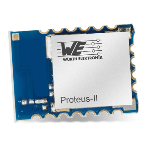
Wurth Elektronik ANR004 Proteus User manual

ANR004 PROTEUS
HOW TO USE THE PERIPHERAL ONLY MODE
VERSION 2.4
FEBRUARY 16, 2021

Revision history
Manual
version Notes Date
1.0 • Initial version February 2017
1.1 • Updated MTU size to 247 bytes July 2017
2.0 • New corporate design June 2018
2.1 • Updated product name from AMB2621 to Proteus-I November 2018
2.2
• Updated file name to new AppNote name structure.
Updated important notes, legal notice & license terms
chapters. June 2019
2.3
• Added Proteus-II and Proteus-III description
• Updated address of Division Wireless Connectivity &
Sensors location
January 2020
2.4
• Restructured app note
• Added new chapter
Quickstart
with new connection setup
examples
• Added information on the Proteus-III mini evaluation board
February 2021
ANR004 Proteus version 2.4 © February 2021
www.we-online.com/wireless-connectivity 1

Abbreviations and abstract
Abbreviation Name Description
BTMAC Bluetooth®conform MAC address of the module used
on the RF-interface.
CS Checksum Byte wise XOR combination of the preceding fields.
DTM Direct test mode Mode to test Bluetooth®specific RF settings.
GAP Generic Access
Profile
The GAP provides a basic level of functionality that all
Bluetooth®devices must implement.
I/O Input/output Pinout description.
LPM Low power mode Mode for efficient power consumption.
LSB Least significant
bit
MAC MAC address of the module.
MSB Most significant bit
MTU Maximum
transmission unit Maximum packet size of the Bluetooth®connection.
Payload The intended message in a frame / package.
RF Radio frequency Describes wireless transmission.
RSSI Receive Signal
Strength Indicator
The RSSI indicates the strength of the RF signal. Its
value is always printed in two’s complement notation.
Soft device Operating system used by the nRF52 chip.
UART
Universal
Asynchronous
Receiver
Transmitter
Allows the serial communication with the module.
[HEX] 0xhh Hexadecimal
All numbers beginning with 0x are hexadecimal
numbers. All other numbers are decimal, unless
stated otherwise.
ANR004 Proteus version 2.4 © February 2021
www.we-online.com/wireless-connectivity 2

Contents
1 Introduction 4
2 Prerequisites 5
3 Peripheral only mode: General information 6
3.1 How to set the Proteus radio module to peripheral only mode? . . . . . . . 6
3.2 General connection setup information . . . . . . . . . . . . . . . . . . . . . 9
3.3 Preconfiguring of the module . . . . . . . . . . . . . . . . . . . . . . . . . . 10
4 Quickstart 12
4.1 Smart phone using nRFConnect app as central device . . . . . . . . . . . . 12
4.2 Smart phone using Proteus Connect app as central device . . . . . . . . . 22
4.2.1 Background service on iOS . . . . . . . . . . . . . . . . . . . . . . 30
4.3 Proteus module or plug as central device . . . . . . . . . . . . . . . . . . . 31
5 References 34
6 Important notes 35
6.1 General customer responsibility . . . . . . . . . . . . . . . . . . . . . . . . . 35
6.2 Customer responsibility related to specific, in particular safety-relevant ap-
plications ..................................... 35
6.3 Best care and attention . . . . . . . . . . . . . . . . . . . . . . . . . . . . . 35
6.4 Customer support for product specifications . . . . . . . . . . . . . . . . . . 35
6.5 Productimprovements.............................. 36
6.6 Productlifecycle ................................. 36
6.7 Propertyrights .................................. 36
6.8 General terms and conditions . . . . . . . . . . . . . . . . . . . . . . . . . . 36
7 Legal notice 37
7.1 Exclusionofliability................................ 37
7.2 Suitability in customer applications . . . . . . . . . . . . . . . . . . . . . . . 37
7.3 Trademarks .................................... 37
7.4 Usagerestriction ................................. 37
8 License terms 39
8.1 Limitedlicense .................................. 39
8.2 Usageandobligations .............................. 39
8.3 Ownership..................................... 40
8.4 Firmwareupdate(s)................................ 40
8.5 Disclaimerofwarranty .............................. 40
8.6 Limitationofliability................................ 40
8.7 Applicable law and jurisdiction . . . . . . . . . . . . . . . . . . . . . . . . . . 41
8.8 Severabilityclause ................................ 41
8.9 Miscellaneous................................... 41
ANR004 Proteus version 2.4 © February 2021
www.we-online.com/wireless-connectivity 3

1 Introduction
The Proteus is a Bluetooth®module based on the nRF52 Nordic Semiconductors SoC which
provides various Bluetooth®LE and low power features.
In addition to the standard command mode, that uses predefined commands to run and
configure the radio module, Würth Elektronik eiSos launches the "peripheral only mode" on
the Proteus to use the module as Bluetooth®LE bridge in a simple way.
In this mode, a Bluetooth®LE interface using the static passkey authentication method (with
bonding) and a transparent UART interface is provided, such that no configuration of the
module is required to equip a custom application with it.
In case the user needs a non-standard configuration, it can be configured in advance using
the command mode, or upon request Würth Elektronik eiSos can apply customer specific
configurations during the production process.
The following chapters describe how to set the module into peripheral only mode and which
steps have to be applied to establish a connection to the radio module.
ANR004 Proteus version 2.4 © February 2021
www.we-online.com/wireless-connectivity 4

2 Prerequisites
• A Proteus evaluation board in factory state, for example
–the Proteus-I evaluation board with firmware version 3.0.0 or newer.
–the Proteus-II evaluation board.
–the Proteus-III evaluation board or mini evaluation board.
• A central device, that initiates the connetion setup. For example
–a smart phone with Bluetooth®LE function and the Nordic Semiconductor nRF
Connect App.
–another Proteus evaluation board or mini evaluation board.
–a Proteus Plug (radio stick containing a Proteus radio module).
Figure 1: Proteus-III evaluation board
To be sure that the Proteus radio module or Proteus Plug is in factory state,
please run a factory reset before doing any other action.
Please check whether the most recent firmware is installed on any Proteus
radio module, EV board or Proteus Plug.
ANR004 Proteus version 2.4 © February 2021
www.we-online.com/wireless-connectivity 5

3 Peripheral only mode: General information
For a better understanding of the content of this chapter, basic knowledge of the Bluetooth®
standard as well as that of the SPP-like profile is of advantage. Please find more details on
that in the respective advanced developer guide:
• ANR002 Proteus-I advanced developer guide
• ANR005 Proteus-II advanced developer guide
• ANR009 Proteus-III advanced developer guide
3.1 How to set the Proteus radio module to peripheral only mode?
The Proteus starts in peripheral only mode, when a HIGH level is applied at the OPERA-
TION_MODE pin and a reset is done via the /RESET pin. If the OPERATION_MODE pin is
LOW during the reset, the module starts in normal operation mode with command interface.
A pull-down is applied to the OPERATION_MODE pin during start-up. Thus
increased currents can occur for a period ≤1 ms.
After the start-up procedure has been finished, the OPERATION_MODE pin
and thus the applied signal level has no function.
For Proteus-III, the OPERATION_MODE pin has been renamed to MODE_1,
while maintaining the same function. Throughout this app note we will use
OPERATION_MODE as a term for this pin.
In case of the evaluation board for Proteus, simply connect the OPERATION_MODE pin to
VCC by setting the respective jumper (see figure
2
,
3
and
4
). Then press the reset button to
start the module in peripheral only mode.
ANR004 Proteus version 2.4 © February 2021
www.we-online.com/wireless-connectivity 6

Figure 2: On Proteus-I and Proteus-II evaluation board, set these jumpers to start the pe-
ripheral only mode after reset.
Figure 3: On Proteus-III evaluation board, set these jumpers to start the peripheral only mod-
e after reset.
ANR004 Proteus version 2.4 © February 2021
www.we-online.com/wireless-connectivity 7

3.2 General connection setup information
In factory state, the peripheral only mode uses the static passkey pairing with bonding au-
thentication method, which requests a static passkey from the connecting device. Figure
5
shows the steps that have to be performed successively during connection setup using the
static passkey pairing method:
1. Physical connection establishment
A physical connection has to be established first. Therefore, a central device (usually
smart phone) has to connect to the Proteus which runs as peripheral.
2. Pairing process
The authentication and exchange of encryption information is part of the pairing pro-
cess. The central device must request at least the same security level to access the
characteristics of the Proteus. The peripheral only mode uses static passkey bonding
by default. The Proteus waits for the bonding request of the central device to perform
this step.
In case the central device goes on with the next steps without placing this bond-
ing request, the peripheral device disconnects immediately as the required
security level is not achieved. The same holds, if the central device places a
bonding request with lower security level than required by the peripheral device
(static passkey with bonding).
3. Exchange of the maximum transmission unit (MTU)
The maximum transmission unit can be increased to allow the transmission of larger
data packets. The Proteus allows an MTU of up to 247 bytes, which results in a payload
of up to 243 bytes. This step is optional. Not selecting a higher MTU will use the
Bluetooth®LE 4.0 default MTU which results in 19 bytes payload for the user but will
be compatible to pre Bluetooth®LE 4.2 devices.
4. Discover the characteristics of the Proteus SPP-like profile
The characteristics offered by the Proteus have to be discovered by the central.
5. Notification enable
The peripheral must let the central know, when there is new data. Therefore, notifica-
tions have to be enabled. After this step, the channel is open and data transmission
can start.
For the description, we assume that a smart phone is the initiator of the connection. Thus, it
acts as central and the Proteus acts as peripheral in figure
5
.
ANR004 Proteus version 2.4 © February 2021
www.we-online.com/wireless-connectivity 9

Figure 5: Steps for the connection setup in static passkey mode (default)
3.3 Preconfiguring of the module
In case user settings (such as UART baud rate, security mode or the static passkey value)
have to be modified, please start the module in normal mode (apply a low signal at the
OPERATION MODE pin during start-up). Then use the commands like
CMD_SET_REQ
to
update these user settings and switch back to peripheral only mode (apply a high signal to
the OPERATION MODE pin during start-up).
ANR004 Proteus version 2.4 © February 2021
www.we-online.com/wireless-connectivity 10

For security reasons it is strongly recommended to change the default
RF_StaticPasskey
to a customer specific passkey.
Custom product: Upon request Würth Elektronik eiSos can apply customer
specific configuration(s) during the production process.
ANR004 Proteus version 2.4 © February 2021
www.we-online.com/wireless-connectivity 11

4 Quickstart
In chapter
3.2
, it has been described which steps have to be performed by the central device
to setup a connection to a Proteus radio module running in peripheral only mode. What this
means in practice will be shown in this chapter. Two examples are following. First, how
to use a smart phone and the nRF Connect App to setup a connection to a Proteus radio
module running in peripheral only mode (see chapter
4.1
). And second, how to use another
Proteus radio module or Proteus plug to do so (see chapter
4.3
).
4.1 Smart phone using nRFConnect app as central device
This chapter describes how to setup a connection to the Proteus radio module in peripheral
mode (factory state), when a smart phone and the nRF Connect App are used.
The nRF Connect App is an open source App providing standard
Bluetooth®LE functions for iOS as well as for Android devices.
Please perform the following steps:
ANR004 Proteus version 2.4 © February 2021
www.we-online.com/wireless-connectivity 12

Android iOS
• Connect the module to a PC and open a terminal program using the Proteus
default UART settings (115200 Baud, 8n1).
• Set the module into peripheral only mode as described in chapter
3.1
. Initially,
the module is advertising. Thus the Proteus LED_1 is blinking.
• Start your smart phone, enable the Bluetooth®LE feature and start the nRF Con-
nect App.
• Press "SCAN" to find the module on the radio.
• When the module A-xxxxxx appears, press connect. (Note: the part after "A-" is
the 3 LSB as ASCII hex of the BTMAC, the fixed part "0x0018DA" is not part of
the device descriptor).
ANR004 Proteus version 2.4 © February 2021
www.we-online.com/wireless-connectivity 13

Android iOS
• As soon as the module has received the connection request the module LED_1
(LED_3 on the Proteus-EV) will constantly light up.
• Then the radio module requests for the static passkey. In default, the passkey is
"123123".
• The Bluetooth®coupling requirement popup is shown in your smartphone.
• When the bonding feature is enabled in the authentication settings and the bond-
ing information already exists, a re-entering of the passkey is not required when
reconnecting.
ANR004 Proteus version 2.4 © February 2021
www.we-online.com/wireless-connectivity 14

Android iOS
• Now you are authenticated.
• Please click on the menu bullets on
the right and press "Request MTU" to
request for a larger MTU.
• Now you are authenticated.
• Please click on the "Unknown Ser-
vice" to start the service discovery
and the MTU request.
ANR004 Proteus version 2.4 © February 2021
www.we-online.com/wireless-connectivity 15

Android iOS
• Again click on the menu bullets on the
right and press "Enable services" to
enable the notifications.
• Press the arrows on the RX-
characteristic
6E400003- C352-
11E5- 953D -0002A5D5C51B
to en-
able the notifications. Press it until
a cross appears (see below, it has
to be pressed at least once). If a
cross is already shown press it twice
so the cross disappears and then
reappears.
• As soon as the module has received the notification enable request the Proteus
LED_2 (LED_2 on the Proteus-EV) is turned on.
ANR004 Proteus version 2.4 © February 2021
www.we-online.com/wireless-connectivity 17

Android iOS
• Now you are fully connected and you can access the characteristics. The max-
imum size of payload depends on the chosen MTU size. Here we chose 247
bytes, which allows us to send 243 bytes of payload via the channel.
• To send data to the Proteus, press the arrow next to the TX-characteristic
6E400002-C352-11E5-953D-0002A5D5C51B
.
• Then enter 0x01 as header byte followed by your payload (for example 0x11
0x22 0x33 0x44) and press "SEND". The payload size is dependent on the MTU
that was negotiated in the connection process. The smallest supported MTU for
all Bluetooth®4.0 (or newer) devices results in a max payload (after the 0x01
header) of 19 bytes.
ANR004 Proteus version 2.4 © February 2021
www.we-online.com/wireless-connectivity 18

Android iOS
• The payload that has been sent via radio is output by the Proteus via UART. In
peripheral only mode, a transparent UART interface is used. This means, that
only payload data is transmitted, without any packet header or footer. Thus the
transmitted bytes 0x11 0x22 0x33 0x44 are displayed on the connected terminal
program.
ANR004 Proteus version 2.4 © February 2021
www.we-online.com/wireless-connectivity 19
Table of contents
Other Wurth Elektronik Control Unit manuals
Wurth Elektronik
Wurth Elektronik Proteus-E User manual

Wurth Elektronik
Wurth Elektronik PROTEUS-II User manual

Wurth Elektronik
Wurth Elektronik SETEBOS-I User manual

Wurth Elektronik
Wurth Elektronik Telesto-II User manual

Wurth Elektronik
Wurth Elektronik THYONE-I User manual
Wurth Elektronik
Wurth Elektronik Proteus-E User manual

Wurth Elektronik
Wurth Elektronik ANR005 Proteus-II Instruction Manual

Wurth Elektronik
Wurth Elektronik CALYPSO User manual