Wybron Coloram IT User manual

Coloram IT
User Manual

2
84520 4-inch Coloram IT Color Changer
87110 7.5-inch Coloram IT Color Changer
810100 10-inch (2K) Coloram IT Color Changer
Coloram IT software version: V1.2
Manual issue date: October 16, 2006
CONTENTS
Declaration of Conformity .......................................... 3
Safety Information...................................................... 4
Introduction ................................................................ 5
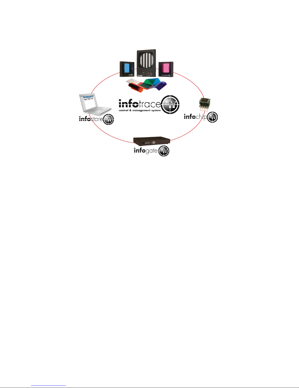
InfoTrace System Overview....................................... 6
InfoTrace Connection Diagram .................................. 9
Quick Start ................................................................. 9
Using The Coloram IT Color Changer...................... 10
Coloram IT System Components............................. 11
Color Changer......................................................11
Gelstring...............................................................11
Power Supply.......................................................11
Cables..................................................................12
Coloram IT Menus ................................................... 15
Alerts/Error Messages..........................................17
DMX Address.......................................................19
Settings................................................................20
Sensor Info...........................................................21
Self Test (Demo)..................................................23
History..................................................................23
Reset Defaults.....................................................25
Head-Feet Restrictions ............................................ 26
Mounting and Installation Accessories..................... 27
Color Changer Mounting Plates............................... 27
Replacing a Gelstring............................................... 28
Equipment Compatibility .......................................... 30
RDM Equipment and InfoTrace................................ 30
Coloram IT Products and Standard Environments... 30
Specifications........................................................... 31
Parts list ................................................................... 31
Warranty Information ............................................... 33
ColorExpress IT Gelstrings ...................................... 34

3

4
Safety Notice
SAVE THESE INSTRUCTIONS
READ AND FOLLOW ALL INSTRUCTIONS
This manual gives step-by-step instructions for preparation, setup and
operation of the Coloram IT Color Changer.
There is a potential risk of injury to persons if the product is not used as
instructed.
The Coloram IT is not intended for residential use.
WARNING: When using electrical appliances, use basic precautions,
including:
!Read this manual before connecting power.
!Use supervision around children.
!Do not touch moving parts.
!Only use attachments recommended or sold by Wybron.
!Use in a dry location only.
Replace only with same type and rating of fuse.
For questions, contact Wybron at 1-800-624-0146.
Product Modification Warning
Wybron, Inc. products are designed and manufactured to meet the
requirements of United States and International Safety standards.
Modifications to the products could affect safety and render the product non-
compliant to relevant safety standards.

5
Introduction
The Coloram IT system includes a scrolling color changer and PS Power Supply, that
uses Remote Device Management (RDM) bi-directional communications protocol, in a
range of models and offers an ease of setup and use. The Coloram IT system is part of
the InfoTrace system that represents a new way of managing a lighting installation.
The Coloram IT system, with its variable color capacity, RDM features and DMX
compatibility affords the designer economy and versatility, particularly when budget and
space are limited. The lightweight color changers slide easily into the gel frame holder of
the light fixture. The compact power supplies attach effortlessly to the truss of the lighting
rig or mount into a 19-inch rack.
The DMX512 control signal from the lighting console is connected through the InfoGate
Gateway and dimmers to the PS Power Supply, and can continue on to additional PS
Power Supplies or other DMX-controlled devices. The power supply sends power, DMX
control signal and RDM information to the color changers on a single cable, eliminating
the need for a separate power cable for the color changers.
Coloram IT color changers are 100% compatible with all members of the Coloram IT
family including CXI IT color changers, PS Power Supplies, the Eclipse IT Dowser and
Eclipse II IT Dowser. You can also daisy chain Coloram IT color changers with other
Coloram IT equipment.
This manual gives step-by-step instructions for preparation, setup and operation of the
Coloram IT Color Changer as part of the InfoTrace system.
Caution:
The Coloram IT System is not compatible with Coloram II (RAM) System.
Do not connect Coloram IT Color Changers to Coloram II (RAM) Power Supplies.
Do not connect Coloram II color changers to PS Power Supplies.
Damage from such action will not be covered by the product warranties.

6
InfoTrace System Overview
Figure 1
The diagram above outlines the key components, which include:
InfoTrace – The entire system is referred to as the InfoTrace System
InfoGate – The software and hardware required to facilitate the transfer and
display of information
InfoChip – A conversion chip that can be used with non-RDM equipment to
allow communication with the InfoGate Software
InfoStore – An Internet based application that aggregates data captured by
InfoGate and allows for the accumulation of historical information
related to the equipment performance in the installation
IT Products – Coloram IT, CXI IT, Eclipse IT, and Eclipse II IT all have updated
electronics to support RDM communication plus additional product
improvements, including sensors to detect a variety of conditions.
The heart of the InfoTrace (IT) system is InfoGate — specialized software that uses the
bi-directional communications protocol, Remote Device Management (RDM), to facilitate
remote addressing and diagnostics for potentially every piece of equipment mounted on a
rig. InfoGate works with all IT products and all RDM-compatible equipment from any
manufacturer.
In addition, any non-RDM equipment can be upgraded with the installation of an InfoChip.
Because InfoGate can work with any equipment, the setup, unit testing, and

7
troubleshooting for an entire rig can be coordinated from a single laptop.
Wybron's IT equipment (Coloram IT, CXI IT, Eclipse IT, and Eclipse II IT) is equipped
with a series of sensors that can relay a wealth of information to InfoGate. These
sensors can detect everything from light, voltage, current, to fan speed and even
gelstring frame color information.
So while RDM equipment will allow identification and remote addressing, IT equipment
can give more specific status information and warn of potential problems, possibly
averting failures in the middle of a show. If the status of a device indicates any problem,
InfoGate displays an alert with the nature of the problem and the exact location.
Troubleshooting is now done in a fraction of the time.
InfoTrace provides the ability to:
• Automate the setup of DMX addresses – no more manual setting of DIP switches
• Proactively check the condition of equipment before, during and after a show
• Track lamp duty cycles to predict lamp failures before they happen
• Predict maintenance on equipment
• Predict gel replacement prior to degradation
Sensors
Coloram IT, CXI IT, Eclipse IT and Eclipse II IT:
• Aperture Light Sensor: Detects if the fixture's lamp is on.
• Voltage Sensor: Reports the head voltage level.
• Pass Through Current Sensor: Measures the amount of current that passes through the
XLR connector wiring harness; assists in automatically setting up the rig in
conjunction with InfoGate.
• Unit Current Sensor: Measures the amount of current that a unit is consuming, which
can be an indicator of motor health.
• Timers: Keep track of how many hours the unit has been in operation in it’s lifetime and
also since its last maintenance cycle.
• Fan RPM Sensor: RPM sensor on fan.
• Self Test Mode: Moves the gelstring without a DMX input command.
• Reverse Polarity Protection: Auto shutdown if scroller is plugged into a Coloram II
power supply.

8
Additional Sensors
Coloram IT and CXI IT only:
• Gel Color Reader: Reads digital information off of the gelstring, including gelstring frame
color information.
• Gel Wear Counter: Tracks how much the gelstring has moved and alerts the user when
a gelstring needs to be replaced.
• Gel Temperature Sensor: Approximates and reports the temperature of the gel.
• "Gelstring is broken" Sensor: Detects if the gelstring is broken after gelstring
initialization.
• Motor Shutdown if Gelstring is Broken: Automatically shuts down the motor if the
gelstring breaks or comes loose from a roller.
Alert Warnings include:
• Fan Stopped
• High Motor Current
• Fan Off and Lamp On
• Unit Cleaning Period Reached
• Gelstring Initializaion Fail
• Low Voltage Alert
• Low Voltage Unit Shutdown
• Gelstring out of Position, Unit Shutdown (Coloram IT and CXI IT only)
• Gelstring Replacement Period Reached (Coloram IT and CXI IT only)

9
InfoTrace Connection Diagram
Figure 2
Quick Start
1. Connect the Equipment
A. Attach the Coloram IT Color Changer to a powered light fixture.
B. Connect the Coloram IT Color Changer to the PS Power Supply using the
4-pin Wybron Power/Data Cable.
C. Connect the PS Power Supply to non-dimmed 100-240 VAC, 50/60Hz
power and to a DMX source.
D. Connect dimmers that have InfoChip installed, to the InfoGate hardware
and software. Please refer to the InfoGate and InfoChip manuals for
details.
E. Using InfoGate:
i. Initiate “Perform Discovery”
ii. In the DMX Map, drag and drop the DMX address for the color
changer to DMX address 1.
Please refer to the InfoGate manual for details.

10
2. Send DMX Levels
A. From the lighting console, vary the level of the Coloram IT on DMX address
1 to move the gelstring back and forth. Please refer to the InfoGate manual
for details.
Using the Coloram IT Color Changer
The Coloram IT Color Changer sets its gelstring position according to the DMX512 level it
receives from the control console. As all Coloram IT Color Changers will accommodate
variable length gelstrings, the level settings which correspond with each frame position
will vary depending on the number of frames in the gelstring.
The following chart shows the level settings that correspond with each frame position if a
24 frame gelstring is installed on a 7.5-inch color changer. The color of each frame
position will be determined by your custom gelstring specification.
Channel
Level
Frame
Position
Channel
Level
Frame
Position
00
Frame 1
51
Frame 13
04
Frame 2
55
Frame 14
09
Frame 3
59
Frame 15
12
Frame 4
64
Frame 16
17
Frame 5
69
Frame 17
21
Frame 6
73
Frame 18
25
Frame 7
78
Frame 19
29
Frame 8
82
Frame 20
34
Frame 9
87
Frame 21
38
Frame 10
91
Frame 22
42
Frame 11
96
Frame 23
47
Frame 12
FL
Frame 24
If you send a channel level that is between the values shown, you can create split frame
effects. For example, if you send a level of 49, the color changer positions the gelstring
halfway between frame 12 and frame 13 creating a blend of the two colors.
Alternately, when the InfoGate information is exported to some types of lighting consoles,
each gelstring frame position can be programmed as a gel color, frame number or other
identifier. The desired gelstring frame is then recalled by selecting the desired gelstring
frame (i.e. Frame 09) or gel color (R68) on the lighting console, instead of typing in a
DMX level.

11
Coloram IT System Components
Color Changers
All Coloram IT Color Changers use gelstrings which can vary in length. The color
changers set the position of the gelstring as determined by the DMX level. The color
changers are powered by 24 volts DC which also comes from the power supply. The
control signal, RDM data and DC power are all supplied in one cable connecting the color
changers to the power supply.
Note: Please refer to the Specifications section of this manual for the maximum number
of gelstring frames each color changer will hold.
Gelstring
The gelstring is a series of precisely cut, colored gel frames joined together, side by side,
to create a sequence of colors. Two additional gels at each end of the gelstring are called
the leader and the trailer. The leader and the trailer allow for proper attachment to the
rollers. The gelstring has foil tags near each end which are necessary for the color
changer's automatic calibration to the length of that particular gelstring.
Figure 3
The Coloram IT gelstring also has a radio frequency identification (RFID) tag which
identifies the sequence of gels on the gelstring (as part of the InfoTrace setup process),
and also assists in ordering additional gelstrings. Please refer to the ColorExpress IT
section of this manual for information on how to create and order gelstrings online.
Power Supply
The PS Power Supply sends the DMX512 signal level from the lighting console to each
color changer, along with 24 volts DC. RDM information is sent from the Coloram IT
Color Changer to the InfoGate software installed on a Mac or PC.
Leade
r
Frame
1
Frame
2
Frame
31
Frame
32
Traile
r
Long foil
tag
Short foil
tag
RFID tag

12
Cables
Power/Data cable
The 4-pin Power/Data Cable connects the PS Power Supply outputs to the Coloram IT
Color Changers and provides them with power and control signal.
The Power/Data cable uses 4-pin XLR connectors on either end and consists of two 14
AWG conductors and a 22 AWG twisted, shielded pair. The shells of the two XLR
connectors are not electrically connected -- this prevents high power currents from
flowing from chassis to chassis of the Coloram IT equipment. The twisted pair shield is
connected only at the male XLR connector end. This is the standard Wybron Power/Data
Cable.
XLR Pin # Wire Color Function Size
1 White Ground 14 AWG
2 Green Data - 22 AWG
3 Red Data + 22 AWG
4 Black 24 Volts DC 14 AWG
Note: The cable used in the Coloram IT System is the same cable which is used in the
Coloram II and Forerunner Systems and may be referred to as Coloram IT, Coloram II or
Forerunner cable.
DMX512 control cable
The DMX control cable from the lighting board to the InfoGate Gateway, dimmers and
power supply is a five conductor cable with 5-pin XLR connectors on each end. The
wiring pin out is specified by the USITT DMX512 / 1990 standard.
XLR Pin # Function
1 Common
2 Data -
3 Data +
4 Talkback -
5 Talkback +
Installing The Coloram IT
1. Attach the color changer to the fixture
Slide the color changer's mounting bracket into the gel frame holder of your fixture and
lock the gel frame retention clip (if available). If the mounting plate installed on your color

13
changer does not fit the fixture, you may be able to replace it with the Wybron Universal
Mounting plate.
The mounting plate allows you to position the
color changer with the gelstring rolling either
horizontally or vertically. However, Coloram IT
operates most effectively with the fan, which is
located in the top of the center panel, blowing air
vertically (as hot air naturally rises).
2. Attach the safety cable
A safety cable is attached to the color changer.
Run this cable around the pipe or truss from
which you hang the light fixture and clip it to
itself.
Figure 4
3. Mount the power supply
The PS Power Supply is designed to be free standing, truss mounted, or rack mounted.
You decide which mounting method best suits your application.
The power supply comes with a mounting bracket which hooks over the pipe or truss of
your lighting rig and is then locked into place with a thumb screw. If you have selected
this mounting method, connect the safety cable by running it around the pipe or truss to
which the power supply is attached.
The power supply can also be mounted into a 19" rack using the optional PS Power
Supply rack mount kit. The rack mount kit will accommodate two PS Power Supplies side
by side.
4. Connect the color changers to the power supply
Connect the color changers to the power supply using 4-pin Coloram IT cable.
Refer to the HEAD-FEET RESTRICTIONS section of this manual for details regarding
the length of cable runs.
5. Connect the power supply to AC power
Plug the AC cord into a non-dimmed power circuit. The power supply automatically
accommodates 100 - 240 VAC (50/60 Hz).
Power at the PS Power Supply is indicated by a red LED indicator.
The connected color changers will automatically "calibrate" themselves to the gelstring
installed by doing the following actions:

14
a. Moving the gelstring toward the last frame, in search of the
long foil tag.
b. Turning around at the long foil tag and then searching for the
short foil tag at the beginning of the gelstring.
c. Stopping at the short foil tag and staying there if no DMX
signal is present or going to its commanded position if DMX
signal is present.
Note: It may take up to 30 seconds before all color changers start to initialize.
Caution: Do not power the PS Power Supply from a dimmer. Severe
damage will result and is not covered by product warranty.
6. Connect the DMX512 source
Connect the DMX512 signal source to the DMX input connector on the front of the power
supply using standard DMX cable. Valid DMX signal will be indicated by a green LED.
The color changers will now position their gelstrings according to their respective DMX
signal levels.
Please refer to the InfoGate manual for further details about how lighting fixtures and
Coloram IT color changers can be automatically paired together and remotely assigned
DMX addresses using InfoGate.

15
[Alerts Menu] >
[DMX Status]
DMX Address: 512
Settings >
Sensor Info >
History >
Reset Defaults >
GEL ALERT
GEL STRING OUT OF
POSITION - UNIT
SHUT DOWN
Reset this Alert? No/Yes
GEL ALERT >
FAN ALERT >
Reset all Alerts? No/Yes
DMX Addresses >
Fan Speed >
Gel Move Speed >
Settings
Continued next
page…
Multiple Alerts
Example
Single Alert
Example
Alerts Menu
This menu only displays when
there is an active alert on the unit.
Gel Move Speed
DMX Status
Displays status of incoming DMX
signal. Examples:
“No DMX Data” or
“DMX Signal OK”
DMX Address
Displays current DMX Address
that can be selected and
modified, using unit buttons.
Fan Speed
DMX Addresses
Device addresses can be
modified from this screen.
Scroller Address 1
Fan Speed Addr 2
Time/Dest Addr 3
Note: The unit only supports one
secondary address at a time. You
can have Fan Speed on a remote
channel or Time To Destination
(Time/Dest) on a remote channel
but not both remotely controlled at
the same time.
Note: The unit will remember its
DMX Address when unplugged.
FAN high
SPEED
high
GEL TTD info >
MOVE
SPEED
Gel Move Speed Options:
High - default
Low
Time/Dest - control
remotely via assigned
DMX channel
Main LCD Menu
Fan Speed Options:
High - default
Low
Remote - control remotely
via assigned DMX channel
Time/Dest Addr 3
Information >
TTD info
Information
Chart of information
regarding time to
destination remote
settings. No changes can
be made from this screen.
COLORAM (IT)
Graphical Menu Tree
TIME 95-100%: Hi
TO 90-94%: Low
DEST 85-89%: 80 sec
INFO 80-84%: 70 sec
ONLY 75-79%: 60 sec
70-74%: 50 sec
65-69%: 40 sec
60-64%: 35 sec
55-59%: 30 sec
50-54%: 25 sec
45-49%: 20 sec
40-44%: 15 sec
35-39%: 10 sec
30-34%: 9 sec
25-29%: 8 sec
20-24%: 7 sec
15-19%: 6 sec
10-14%: 5 sec
5-9%: 4 sec
0-4%: ASAP

16
Gel String Info >
Voltage >
Fan RPM >
Sensor Info
Gel String History >
Operating Hours >
Host Light Lamp >
History
RESET No/Yes
FACTORY
DEFAULT
SETTINGS?
Reset Defaults
[Alerts Menu] >
[DMX Status]
DMX Address: 512
Settings >
Sensor Info >
History >
Reset Defaults >
Main LCD Menu
Gel Wear Gauge >
Frame # vs. Color >
String Description >
Gel String Info
VOLTAGE
Now = 23.8V(15V min)
High = 23.8V(24V max)
Low = 23.7V(15V min)
Reset Hi & Low? No/Yes
Voltage
Fan RPM OK? Yes
Fan RPM
GEL
WEAR
GAUGE
New
Replace
#1 W0
GEL #2 G1
FRAME #3 L2
COLOR #4 L1
#5 G8
#6 R1
Frame # vs. Color
Gel Wear Gauge
ColorExpress
GEL String for
STR. Midsummer
DESC. Dream
9/2006
String Description
Tot Time: 12hr
Tot Moves: 549
Tot Dist: 0 met
Avg Move: 0 cm
Avg Vel: 168 cm/sec
Max at frame: 22400
Gel String History
Cleaning Info >
Maintenance Info >
Lifetime Hours is 287
Operating Hours
Host Light Lamp
RESET No/Yes
HOST LIGHT
LAMP HOURS
GAUGE?
Reset
HOST
LAMP
HOURS:
16 HR
Reset >
New
500 hrs
Cleaning Info
SINCE
CLEAN
RESET:
287 HR
Reset >
Like
New
Needs
Cleaning
Maintenance Info
SINCE
MAINT
RESET:
287 HR
Reset >
Like
New
Needs
Maint.
RESET No/Yes
MAINTEANCE
HOURS
GAUGE?
Reset
RESET No/Yes
CLEANING
HOURS
GAUGE?
Reset
Note: This gauge is
maintained in the
RFID Gel String Tag.
Not on the device.

17
MENU DETAILS
1. Use the !and "buttons to scroll through selections on Coloram IT display.
2. Press SELECT to activate that selection.
Figure 5
The !and "buttons are also used to navigate to further levels within the display.
For example, to select “Scroller Address”:
1. Use the !and "buttons to move to the selection box to “Settings”.
2. Press SELECT to select “Settings”.
3. Use the !and "buttons to move to the selection box to “DMX Addresses”.
4. Press SELECT to select “DMX Addresses”.
5. Use the !and "buttons to move to the selection box to “Scroller Address”.
6. Press SELECT to select “Scroller Address”.
Alerts / Error Messages
The following is an explanation of alerts and error messages that are displayed locally on
the color changer.
To read alert messages:
1. When “SENSOR ALERT” is displayed, press SELECT.
2. As an example: “VOLTAGE ALERT” indicates a voltage problem.
3. Press SELECT to access more information on the Voltage Alert.
4. For example: “WARNING – VOLTAGE
DROPPED BELOW 15V”
VOLTAGE ALERTS
• “WARNING – VOLTAGE
DROPPED BELOW 15V”

18
Operating voltage has dropped below the minimum operating requirement
of 15 volts. The cable between the Coloram IT and the PS Power Supply
may be too long.
• “VOLTAGE DROPPED
BELOW 13V
UNIT SHUTDOWN”
Unit has automatically shut down because operating voltage has dropped
below 13 volts for more than one second. The voltage typically drops this
low if the Coloram IT cable is too long — the head-feet limit has been
exceeded. The Coloram IT cable must be shortened or the number of
Coloram IT scrollers must be reduced to solve this problem.
GEL ALERTS
1. “GELSTRING OUT
OF POSITION — UNIT
SHUTDOWN”
Scroller motor automatically shuts down if gelstring is not at its programmed
frame position or a roller is stuck.
2. “GELSTRING DID
NOT INIT PROPERLY”
Gelstring did not initialize properly. Please check that gelstring is properly
installed.
3. “GELSTRING IS
BROKEN —
UNIT SHUTDOWN”
Scroller motor automatically shuts down if gelstring has broken or come
loose from a roller. Gelstring needs to be replaced or reinstalled.
MOTOR ALERT
1. “MOTOR IS
OPERATING AT A HI
CURRENT LEVEL”
High current level at the scroller motor may indicate an ususually high level
of friction at the motor. Please check scroller motor for possible
maintenance or replacement.
FAN ALERT
1. “FAN IS OFF WHILE
THE LAMP IS ON”
The color changer may overheat or premature fading of the gelstring colors
may occur when the scroller fan is off while the fixture lamp is on.

19
2. “FAN IS NOT
OPERATING
PROPERLY”
Check fan for possible maintenance.
RFID ALERTS
1. “RFID TAG —
COMMUNICATION FAILURE”
A. Communication could not be established with the RFID tag.
B. Press SELECT for more detailed information:
i. “COULD NOT WAKE
THE RFID TAG”
RFID wake command did not finish.
ii. “COULD NOT READ
THE RFID TAG”
Coloram IT had a communication failure when trying to read
the RFID tag.
iii. “COULD NOT WRITE
THE RFID TAG”
Coloram IT had a communication failure when trying to write
to the RFID tag.
RESET ALERT
Clears existing alert from display screen when you press SELECT, unless the problem
still currently exists.
MULTIPLE ALERTS
1. Press SELECT to read the first alert.
2. Press SELECT to read the details of the first alert.
3. Press BACK to view the second alert.
4. Press SELECT to view details of the second alert.
5. Press BACK to check if there any additional alerts, repeat Steps 4 and 5 until all
alerts have been read.
6. Once all alerts have been read, use the dkey to move the selection box to the
“RESET ALL ALERTS” command.
7. Press SELECT to clear all alerts, except for those that currently exist as problems.
DMX Address
1. Use the !and "buttons to select the desired Coloram IT DMX address.

20
2. Press SELECT to activate the displayed Coloram IT DMX address.
Settings
DMX ADDRESSES
Scroller Addr (Scroller Address)
A. Use the !and "buttons to select the desired Coloram IT DMX address.
B. Press SELECT to activate the desired Coloram IT DMX address.
Fan Speed Addr (Fan Speed Address)
A. Selecting a DMX address for Fan Speed Address also automatically sets
Fan Speed to “REMOTE” (see “Fan Speed” below).
B. Use the !and "buttons to select the desired DMX address.
C. Press SELECT to activate the desired DMX address.
Time/Dest Addr (Time to Destination Address)
If this function is enabled, this feature controls the time it takes to arrive at the
destination gelstring position after the new destination command is sent.
A. Use the !and "buttons to select the desired DMX address.
B. Press SELECT to activate the desired DMX address.
FAN SPEED
1. Use the !and "buttons to select High (normal setting), Low or Remote.
A. REMOTE assigns Fan Speed control to the lighting console where:
51% to 100% = Fan at High (normal) setting
0% to 50% (except 8%) = Fan at Low setting
8% = Off
GEL MOVE SPEED
1. Use the !and "buttons to select High, Low or Time/Dest (Time to Destination).
2. Press SELECT to activate the desired setting.
TTD Info (Time to Destination information)
A. Gel Time to Destination DMX Address — use the !and "buttons to select
the desired DMX address.
i. If this function is enabled, this feature controls the time it takse to
arrive at the destination gelstring position after the new destination
command is sent.
ii. The DMX address for this feature can also be set at the alternate
display “DMX Address: DMX Addresses: Time/Dest Addr”.
iii. For quietest gelstring movement, select the longest time possible.
iv. Information Only
Displays DMX levels to be used at the lighting console to program
Table of contents
Other Wybron Lighting Equipment manuals
Popular Lighting Equipment manuals by other brands

Loevschall
Loevschall ECO15-12V Instructions for the use

GAME OF BRICKS
GAME OF BRICKS Thor's Hammer 76209 instruction manual

Emos
Emos FIGURES quick guide

SCHOTT
SCHOTT KL 1600 LED operating instructions

thomann
thomann stairville dj lase performance 150 RGY user manual

Odyssey
Odyssey FREEDOM Series Assembly and operation instructions