Wybron 87250 User manual

1
Eclipse IT Iris
User Manual

2
87250 – 1K (7.5-inch) Eclipse IT Iris
810060 – 10-inch Eclipse IT Iris
812020 – 2K (12-inch) Eclipse IT Iris
823020 – 24-inch Eclipse IT Iris
Manual issue date: Feb. 26, 2009
CONTENTS
Declaration of Conformity ...........................................................3
Safety Information.........................................................................4
Introduction....................................................................................5
Quick Start ....................................................................................6
Using the Eclipse IT Iris..............................................................7
Operating Modes................................................................7
Signal and Power...............................................................7
Fan Speed Control ...........................................................7
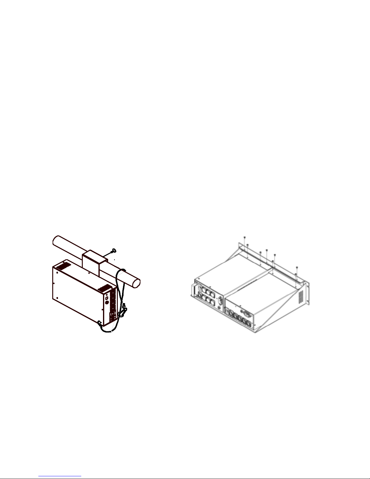
Installing the Eclipse IT Iris ........................................................8
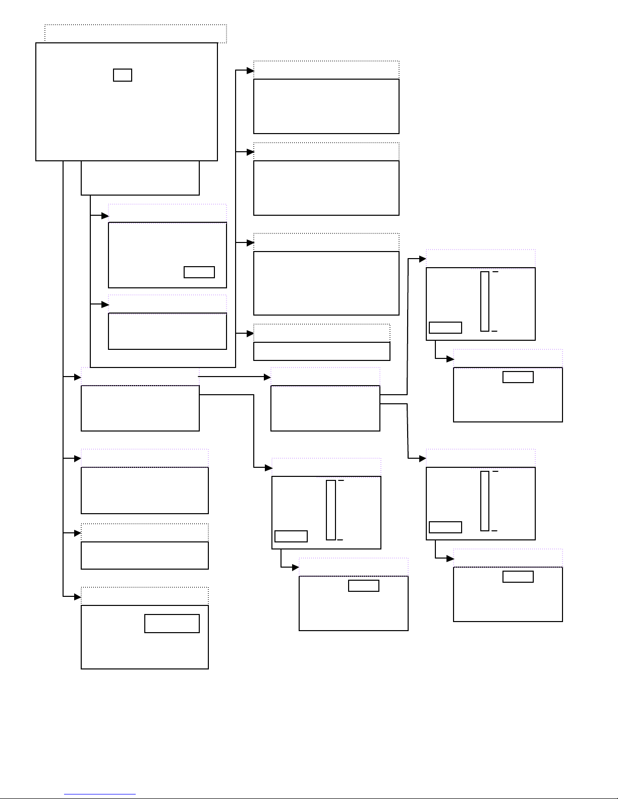
Menu Tree................................................................................... 10
Alerts/Error Messages.................................................. 12
DMX Address.................................................................. 13
Settings .......................................................................... 14
Sensor Info ..................................................................... 14
Self Test (Demo) ........................................................... 15
History.............................................................................. 15
Reset Defaults............................................................... 16
Head-Feet Restrictions............................................................ 17
Equipment Compatibility.......................................................... 18
Cables......................................................................................... 18
Non-RDM Equipment and Infotrace....................................... 19
Coloram IT Products and Standard Environments............. 19
Specifications............................................................................. 20
Parts List..................................................................................... 21
Infotrace System Overview..................................................23
Illustrated Parts Breakdown.................................................... 25
Warranty Information................................................................. 28

3
Safety Notice
SAVE THESE INSTRUCTIONS

4
READ AND FOLLOW ALL INSTRUCTIONS
CAUTION: The Eclipse IT Iris mechanical dimmer/dowser has been
designed to withstand the rigors of entertainment lighting. However, the
teflon coating on the Iris blades can only withstand temperatures up to 600°F.
When used with some excessively hot fixtures, degradation and possibly
flaking of this coating may occur.
USE WITH EXCESSIVELY HOT FIXTURES – OVER 700°F AT THE IRIS
BLADES – THAT RESULTS IN DEGRADATION OF THE HIGH TEMP
POWDER COATING IS EXCLUDED FROM THE PRODUCT WARRANTY.
This manual gives step-by-step instructions for preparation, setup, and
operation of the Eclipse IT Iris dowser.
There is a potential risk of fire, electric shock, or injury to persons if the
product is not used as instructed.
The Eclipse IT Iris dowser is to be used in an indoor environment only and is
not intended for residential use.

5
Introduction
Wybron’s Coloram IT system includes mechanical dowsers (Eclipse IT Iris and Eclipse IT
Shutter) and PS Power Supplies, all utilizing the Remote Device Management (RDM)
industry-standard feedback protocol. Offering a wide range of models with easy setup and
use, the Coloram IT system is part of Wybron’s Infotrace Control and Management System
– a new way to manage an entire lighting installation with RDM feedback
The lightweight Eclipse IT Iris dowser slides easily into the gel frame holder of its light
fixture. The compact PS Power Supply attaches easily to the truss of the lighting rig or
mount into a 19-inch rack.
The DMX512 control signal from the lighting console is connected to the PS Power Supply
and can continue on to additional PS power supplies or other DMX-controlled devices. The
power supply sends power, DMX control signal, and RDM information on a single cable,
eliminating the need for a separate power cable for the dowser.
Eclipse IT Iris dowsers are 100% compatible with all products of the Coloram IT family,
including Coloram IT and CXI IT color changers, PS Power Supplies, and Eclipse IT Shutter
dowsers. Eclipse IT Iris dowsers may be daisy-chained with other Coloram IT devices.
This manual gives step-by-step instructions for preparation, setup, and operation of the
Eclipse IT Iris.
Caution:
The Coloram IT System, including Eclipse IT Iris, is not compatible with Coloram II
(RAM) or Forerunner systems.
Do not connect Eclipse IT Iris dowsers to Coloram II (RAM) power supplies or
Forerunner power supplies.
Do not connect Coloram II (RAM) units to PS power supplies.
Damage from such action will not be covered by the product warranties.

6
Quick Start
1. Connect the Equipment
A. Attach the Eclipse IT Iris dimmer/dowser to a powered light fixture.
B. Connect the Eclipse to the PS Power Supply using the 4-pin Wybron
power/data cable.
C. Connect the PS Power Supply to non-dimmed 100-240 VAC, 50/60Hz power
and a DMX source.
Optional
D. Connect dimmers that have Infochip installed to the Infogate hardware and
software. Refer to the Infogate and Infochip manuals for details.
E. Using Infogate:
i. Initiate “Perform Discovery”
ii. In the DMX Map, drag and drop the DMX address for the Eclipse to DMX
address 1.
F. Refer to the Infogate user manual for further details.
2. Send DMX Levels
A. On the lighting console, vary the level of the Eclipse DMX channel to open and close
the dowser fins.
Connection Diagram
Figure 2
Eclipse Iris IT
Connection Diagram
Figure 1
Four Pin
Optional

7
Using the Eclipse IT Iris Dowser
Operating Modes
The Eclipse has several modes of operation. In all cases, the PS Power Supply is needed
for control and power. Please refer to the Menu Details below for information on how to
select DMX, Local, Snap, Fast, or Smooth mode.
DMX512 Control
The level (0-100%) of the DMX channel to which the dowser is addressed
determines the fin position. The fins are closed at 0% and open at 100%.
Local Wired Pendant Control
A handheld pendant can be attached via a 3-pin XLR cable to manually open and
close the fins. Movement from fully open to fully closed or vice-versa takes two
seconds – this allows for precise fin positioning. Press the " + " button to open the
fins and the " - " button to close them. The wired pendant cable can be up to 1,000
feet long.
Self Test/Demo Mode
The dowser unit can be controlled by the menu buttons on the dowser unit. Please refer to
the Menu Details below, under Self Test (Demo) for details.
Signal and Power
The Eclipse uses a PS Power Supply with Coloram IT cables for DMX signal, RDM
communication and 24VDC power. The dowser can be daisy-chained with Coloram IT and
CXI IT color changers and Eclipse IT Shutter dowsers. Fin position is determined by the
DMX level (0-100%) of the control channel to which the dowser is addressed. The dowser
uses one DMX channel.
Fan Speed Control
The small fan in the Eclipse cools the electronics enclosure, therefore it always runs at full
speed and CANNOT be slowed or stopped.
Installing the Eclipse IT Iris

8
1. Attach the Eclipse to the fixture
Slide the dowser's mounting bracket into the gel frame holder of your fixture and lock the
gel frame retention clip (if available). The unit operates most effectively with the electronics
module oriented to the side or bottom.
2. Attach the safety cable
A safety cable is attached to the dowser. Run this cable around the pipe or truss from which
you hang the light fixture and clip it to itself.
3. Mount the power supply
The PS Power Supply is designed to be free-standing, truss-mounted, or rack-mounted.
You decide which mounting method best suits your application.
The power supply comes with a mounting bracket which hooks over the pipe or truss of
your lighting rig and is then locked into place with a thumb screw. If you have selected this
mounting method, connect the safety cable by running it around the pipe or truss to which
the power supply is attached.
90
-
25
0
VA
C
50
/
60
HZ
4
AM
P
SL
O
-
BL
O
AT
11
5
VA
C
2
AM
P
SL
O
-
BL
O
AT
23
0
VA
C
Figure 2 Figure 3
The power supply can also be mounted into a 19-inch rack using the optional PS Power
Supply rack mount kit. The rack mount kit will accommodate two PS Power Supplies side
by side.
4. Connect the Eclipse to the power supply
Connect the dowsers to the power supply using 4-pin Coloram IT cable.

9
Refer to the HEAD-FEET RESTRICTIONS section of this manual for details regarding the
length of cable runs.
5. Connect the power supply to AC power
Plug the AC cord into a non-dimmed power circuit. The power supply automatically
accommodates 100 - 240 VAC (50/60 Hz).
Power at the PS Power Supply is indicated by a red LED indicator.
Caution: Do not power the PS Power Supply from a dimmer. Severe damage
will result and is not covered by product warranty.
6. Connect the DMX512 source
Connect the DMX512 signal source to the DMX input connector on the back of the power
supply using standard DMX cable. Valid DMX signal will be indicated by a flashing green
LED. The dowsers will now open and close their fins according to their respective DMX
signal levels.
[Alerts Menu] >
[DMX Status]
DMX Address: 512
Settings >
Sensor Info >
History
Local Control >
Reset Defaults >
Multiple Alerts Single Alert
Alerts Menu
This menu only displays when
there is an active alert on the
Eclipse Iris IT
Graphical Menu Tree
[Alerts Menu] >
[DMX Status]
DMX Address: 512
Settings >
Sensor Info >
History
Local Control >
Reset Defaults
Self Test/demo Mode
Reset Defaults

10
Voltage >
Fan RPM >
Operating Hours >
Host Light Lamp >
Fin Cycles = 2140
History
Fin Position
Move Mode: Snap /Smooth
Local Control
[Alerts Menu] >
[DMX Status]
DMX Address: 512
Settings >
Sensor Info >
History >
Reset Defaults >
Main LCD Menu
VOLTAGE
Now = 23.8V(15V min)
High = 23.8V(24V max)
Low = 23.7V(15V min)
Reset Hi & Low? No/Yes
Voltage
Fan RPM OK? Yes
Fan RPM
Cleaning Info >
Maintenance Info >
Lifetime Hours is 25
Operating Hours
Host Light Lamp
RESET No/Yes
HOST LIGHT
LAMP HOURS
GAUGE?
Reset
HOST
LAMP
HOURS:
23 HR
Reset >
New
500 hrs
Cleaning Info
SINCE
CLEAN
RESET:
287 HR
Reset >
Like
New
Needs
Cleaning
Maintenance Info
SINCE
MAINT
RESET:
287 HR
Reset >
Like
New
Needs
Maint.
RESET No/Yes
MAINTEANCE
HOURS
GAUGE?
Reset
RESET No/Yes
CLEANING
HOURS
GAUGE?
Reset
[Alerts Menu] >
[DMX Status]
DMX Address: 512
Settings >
Sensor Info >
History >
Reset Defaults
Local Control
Self Test/Demo Mode >
Now = 00.1A
High = 00.2A
Low = 00.1A
Reset hi & Low? No/Yes
Pass Thru Current
Now = 77F(113F max)
High = 86F(113F max)
Low = 77F(32F max)
Reset hi & Low? No/Yes
AMBIENT TEMP
Now = 27C(47C max)
High = 30C(45C max)
Low = 25C(0C max)
Reset hi & Low? No/Yes
AMBIENT TEMP
Main LCD Menu
Light is off
Light On/ Off
Fade Speed? fast/slow
Self Test/ Demo Mode
RESET
FACTORY
DEFAULT
SETTINGS ?
Reset Defaults
No/yes

11
Menu Details
1. Use the arrow buttons to scroll through selections on the display.
2. Press SELECT to activate that selection or progress to the next level of displays.
Figure 4
The arrow buttons are also used to navigate to further levels within the display.
For example, to select the dowser’s address:
1. Press SELECT.
2. Use the arrow buttons to move to the selection box to “DMX Address.”
3. Press SELECT to select “DMX Address.”
4. Use the arrow buttons to move to the correct address.
5. Press SELECT to save the address.
Alerts / Error Messages
The following is an explanation of alerts and error messages that are displayed locally on
the dowser.
To read alert messages:
1. When “SENSOR ALERT” is displayed, press SELECT.
2. As an example: “VOLTAGE ALERT” indicates a voltage problem.
3. Press SELECT to access more information on the Voltage Alert.
4. For example: “WARNING – VOLTAGE
DROPPED BELOW 15V”
VOLTAGE ALERTS
•“WARNING – VOLTAGE
DROPPED BELOW 15V”
Operating voltage has dropped below the minimum operating requirement of
15 volts. The cable between the unit and the power supply may be too long.

12
•“VOLTAGE DROPPED
BELOW 13V
UNIT SHUTDOWN”
Unit has automatically shut down because operating voltage has dropped
below 13 volts for more than one second. The Eclipse cannot operate properly
below 15VDC. The voltage typically drops this low if the Eclipse IT Iris cable is
too long — the head-feet limit has been exceeded. The cable must be
shortened to solve this problem.
MOTOR ALERT
1. “MOTOR IS
OPERATING AT A HI
CURRENT LEVEL”
High current level at the fin motors may indicate an ususually high level of
friction at the motor. Please check Eclipse motor for possible maintenance or
replacement.
FAN ALERT
1. “FAN IS NOT
OPERATING
PROPERLY”
Check Eclipse fan for any maintenance needs.
RESET ALERT
Clears existing alert from display screen when you press SELECT (unless problem still
currently exists).
MULTIPLE ALERTS
1. Press SELECT to read the first alert.
2. Press SELECT to read the details of the first alert.
3. Press BACK to view the second alert.
4. Press SELECT to view details of the second alert.
5. Press BACK to check if there any additional alerts, then repeat steps four and five
until all alerts have been read.
6. Once all alerts have been read, use the dkey to move the selection box to the
“RESET ALL ALERTS” command.
7. Press SELECT to clear all alerts, except those that currently exist as problems.
DMX Address
1. Use the arrow buttons to select the desired DMX address.
2. Press SELECT to activate the displayed DMX address.
Settings

13
DMX ADDRESSES
Dowser Addr (Dowser Address)
A. Use arrow buttons to select the desired DMX address.
B. Press SELECT to activate the desired DMX address.
MODES
DMX or Local
A. Use arrow buttons to select either DMX or Local mode.
B. Press SELECT to activate the desired setting.
Snap Mode
A. Use the arrow buttons to select either On or Off.
B. Press SELECT to activate the desired setting.
Fast or Smooth
A. Use the arrow buttons to select either Fast or Smooth mode.
B. Press SELECT to activate the desired setting.
Sensor Info
VOLTAGE
1. Displays present voltage and highest and lowest voltages measured, along with
normal minimum and maximum acceptable voltages.
Reset Hi & Low:
A. Use the arrow buttons to select Yes.
B. Press SELECT to activate Reset Hi & Low.
PASS THRU CURRENT
1. Displays present pass through current and highest and lowest current measured,
along with normal minimum and maximum acceptable pass through current.
A. Used in automatically sequencing through RDM enabled units on the lighting
rig during Infogate setup procedures.
Reset Hi & Low:
A. Use the arrow buttons to select Yes.
B. Press SELECT to activate Reset Hi & Low.
FAN RPM
1. Press SELECT to display answer to the question “IS FAN RPM OK?” (Yes or No).

14
Self Test (Demo)
MOVE / STOP
1. Use the arrow buttons to select “Move” or “Stop” fin commands.
2. Press SELECT to activate selected command.
History
OPERATING HOURS
Cleaning Info
A. Lifetime operating hours are shown at the bottom of the first display. This is
the total number of hours the dowser has been in use over its lifetime. This
counter is never reset.
B. Press SELECT to display the gauge that indicates how the Eclipse currently
rates between “Like New” and “Needs Cleaning.”
Figure 5
Cleaning means cleaning dust out of the vent slots, off the printed circuit board, and
off the internal components.
C. The display also shows the number of hours since the last cleaning of
dowser.
Reset Hours
i. Press SELECT to select the Reset Hours function
ii. Use the arrow buttons to select Yes on the “Reset Cleaning Hours
Gauge?”
iii. Press SELECT to activate Reset Cleaning Hours Gauge.
Maintenance Info
A. Lifetime operating hours are shown at the bottom of the first display. This is
the total number of hours the dowser has been in use over its lifetime. This
counter is never reset.
B. Press SELECT to display the gauge that indicates how the dowser rates
between “Like New” and “Needs Maintenance.”

15
Figure 6
Maintenance means replacing a failed part on the dowser.
C. The display also shows the number of hours since the last maintenance on
the dowser.
Reset Hours
i. Press SELECT to select the Reset Hours function.
ii. Use the arrow buttons to select Yes on the “Reset Maintenance Hours
Gauge?”
iii. Press SELECT to activate Reset Maintenance Hours Gauge.
Host Light Lamp
A. Press SELECT to display the gauge that indicates the number of hours that
the lighting fixture lamp has been on since its lamp was installed.
Figure 7
Reset Hours
i. Press SELECT to select the Reset function.
ii. Use the arrow buttons to select Yes on the “Reset Host Light Lamp
Hours Gauge?”
iii. Press SELECT to activate Reset Host Light Lamp Hours Gauge.
Reset Defaults
1. Press SELECT to select “Reset Defaults.”
2. Use the arrow buttons to select Yes to Reset Defaults.
3. Press SELECT to activate Reset Defaults.
Dowser address is 1; DMX control
Head-Feet Restrictions

16
The HEAD-FEET parameter is a method of accounting for the voltage drop in the
power/signal cable caused by the current drawn by each dowser.
To help understand this issue, think of it as water pressure (voltage) in a hose (cable)
feeding multiple water sprinkler heads (dowsers). If the hose (cable) is too long, or too
many sprinkler heads (dowsers) draw from the hose, the water pressure (voltage) will be
too low.
HEAD-FEET is defined as "the sum of cable lengths from each dowser to a single power
supply output.”
Head-Feet Example
Consider this example: Three Eclipse IT Iris units are connected to a power supply. The 4-
pin power/data cable between the power supply and the first Eclipse Iris IT is 100 feet long.
The cable between the first and the second Eclipse is 20 feet long, and the cable between
the second and third Eclipse is also 20 feet long.
The amount of cable from the power supply to:
1st Eclipse IT Iris 100 ft
2nd Eclipse IT Iris 120 ft
3rd Eclipse IT Iris 140 ft
Total: 360 "head-feet"
Head-Feet Limits
•1K (7.5”) Eclipse IT Iris (Model 87250): 1,500 head-feet
•10” Eclipse IT Iris (Model 810060): 1,500 head-feet
•2K (12”) Eclipse IT Iris (Model 812020): 1,500 head-feet
•24” Eclipse IT Iris (Model 823020): 750 head-feet
If a daisy chain includes different models, use the model with the smallest amount of
"head-feet" for the calculation.
Equipment Compatibility/Power Supply Capacity
This chart shows the capacity and compatibility for the various models of PS Power Supply
units and their companion devices.

17
Power Supply
PS-150
PS-300
PS-600
PS-450i
(wall mount)
Model Number
820150
820300
820600
20250
Output Power
150
watts
300
watts
600
watts
300
watts
Quantity Per Power Supply:
Description
Model
Max.
Head-Feet
Coloram IT
4” & 7.5”
84520
87110
1500
6
12
24
12
Coloram IT – 10”
810100
1000
4
8
16
8
CXI IT – 7.5”
87200
1500
6
12
24
12
Eclipse IT Shutter
1K, 2K, Lg Fmt
89020
811020
817020
1500
8
16
32
32
Eclipse IT Iris
1K, 10”, 2K
87250
810060
812020
1500
6
12
24
12
Eclipse IT Iris 24”
823020
750
3
6
12
6
Cables
4-pin Power/Data Cable
The power/data cable uses 4-pin XLR connectors on either end and consists of two 14
AWG conductors and a 22 AWG twisted, shielded pair. The shells of the two XLR
connectors are not electrically connected – this prevents high-power currents from flowing
from chassis to chassis of the equipment. The twisted pair shield is connected only at the
male XLR connector end. This is the standard Wybron power/data Cable.
XLR Pin # Wire Color Function Size
1White Ground 14 AWG
2Green Data - 22 AWG
3Red Data + 22 AWG
4Black 24 Volts DC 14 AWG
Note: The cable used for models of the Eclipse IT Iris is the same cable used for the
Coloram IT, Coloram II, and Forerunner systems. The cable may be referred to as Wybron
4-pin cable.
DMX512 Control Cable
The DMX control cable from the lighting board to the dimmers, power supply, and Wybron’s
Infogate gateway (if used) is a five conductor cable with 5-pin XLR connectors on each end.
The wiring pin out is specified by the USITT DMX512/1990 standard.

18
XLR Pin # Function
1Common
2Data -
3Data +
4Talkback -
5Talkback +
Non-RDM Equipment and Infotrace
A lighting rig can use any combination of non-RDM equipment along with Wybron’s RDM-
compatible equipment. The non-RDM equipment will work the old-fashioned way (hand
addressing, no status reporting or other features). The RDM protocol allows configuration,
status monitoring, and management of RDM devices in such a way that does not disturb
the normal operation of the DMX devices that do not recognize the RDM protocol.
Coloram IT and Standard (Non-RDM) Environments
The Coloram IT family of products (Coloram IT, CXI IT, Eclipse IT Iris, and Eclipse IT
Shutter, which all must be connected to PS power supplies) will work in any standard
environment that does not use Infogate. (For more information about Infogate and Wybron’s
RDM-based Infotrace system, please go to page 23 of this manual.)

19
Specifications
•Fin speed (under DMX control):
Fast cut: 1K/7.5”: 0.73 seconds (fully open to fully closed and vice versa)
10”: 0.85 seconds
2K/12”: 1.0 seconds
24”: 2.0 seconds
Cross fade: up to 60 seconds (movement without stopping)
•Operating modes:
1. DMX512
2. Local wired pendant control
3. Local push button control (push buttons on the Eclipse unit)
•Number of DMX channels used: One
•Status Display: Backlit display
•LED Indicators:
Red: Power
Green: DMX signal
•Wired Pendant Control Cable:
3 conductor with 3-pin XLR connectors
Up to 1,000 feet long
•Control Pendant 3-pin XLR connector pin functions:
Pin 1: Connect to common to open the fins
Pin 2: Connect to common to close the fins
Pin 3: Common
•Current Requirements:
1K/7.5”, 10”, 2K/12”, 24”: 1.0 Amp @ 24 VDC
•Fuse:
1K/7.5”, 10”, 2K/12”, 24”: 1.5 amp Slo-Blo
•Mounting Plates:
Various plates available to fit a wide variety of fixtures
(Please refer to Wybon’s Web site at www.wybron.com for details)
•Fan:
Small, low-speed fan to cool the electronics enclosure
•Safety Cable:
3.5 feet long cable included
•Daisy Chaining:
Individual DMX addresses on one home run
•Power Supply Compatibility:
PS-150 Power Supply (150 watts)
PS-300 Power Supply (300 watts)
PS-600 Power Supply (600 watts)
PS-450i Permanent Install Power Supply (300 watts)
•Signal Termination: None required (depends on system configuration)
•Weight:
87250 — 1K/7.5” Eclipse IT Iris: 4.76 lbs/2.15 kg
810060 — 10” Eclipse IT Iris: 7.00 lbs/2.63 kg
812020 — 2K/12” Eclipse IT Iris: 8.00 lbs/3.63 kg
823020 — 24” Eclipse IT Iris: 31.96 lbs/14.5 kg

20
•Aperture Diameter:
87250 — 1K/7.5” Eclipse IT Iris: 7.5”/190.5mm
810060 — 10” Eclipse IT Iris: 10”/254mm
812020 —2K/12” Eclipse IT Iris: 12.0”/304.8mm
823020— 24” Eclipse IT Iris: 24.5.”/622mm
•Overall Dimensions:
87250 — 1K/7.5”:
10.88"/276.36mm wide x 12.89"/327.41mm high x 4.5"/114.3mm deep
810060 — 10”:
18.36”/466mm high x 15.52”/367mm wide x 4.82”/122mm deep
812020 — 2K/12”:
20.55”/522mm high x 17.88”/454mm wide x 4.83”/123mm deep
823020— 24”
34.66”/880mm high x 34.66”/880mm wide x 9.76”/248mm deep
Parts List
To order any of the following items, contact an authorized WYBRON dealer. Or go to
www.wybron.com
Eclipse IT Iris Dowsers and Power Supplies
87250....................................1K/7.5” Eclipse IT Iris Dowser
810060 .................................10” Eclipse IT Iris Dowser
812020 .................................2K/12” Eclipse IT Iris Dowser
823020 .................................24” Eclipse IT Iris Dowser
820150 .................................PS-150 Power Supply, 150 watts
820300 .................................PS-300 Power Supply, 300 watts
820600 .................................PS-600 Power Supply, 600 watts
20250....................................PS-450i Power Supply, 300 watts (permanent install)
Wybron 4-Pin Cable
7042-3 ..................................3' power/signal cable
7042-5 ..................................5' power/signal cable
7042-10................................10' power/signal cable
7042-15................................15' power/signal cable
7042-25................................25' power/signal cable
7042-50................................50' power/signal cable
7042-75................................75' power/signal cable
7042-100..............................100' power/signal cable
This manual suits for next models
3
Table of contents
Other Wybron Lighting Equipment manuals