X-Factor X-60 User manual

X – 60 Instructions Version 1.0 Page 1
X
–
6
0
CONVERSION KIT
X – 60 ASSEMBLY
INSTRUCTIONS
Version 1.0
www.2wdrc.com

X – 60 Instructions Version 1.0 Page 2
TABLE OF CONTENTS
T4 Disassembly………………………………………………………….... 5
Bag A – Transmission Assembly………………..………………………. 12
Front End Installation……………………………………………………… 17
Bag B – Bulkhead & Transmission Install ……………………………… 20
Bag C – Rear Suspension Assembly…….……………………………… 25
Bag D – Final Assembly………………………………………………….. 29
Tuning Section……………………………………………………………… 33

X – 60 Instructions Version 1.0 Page 3
X – 60 ASSEMBLY INSTRUCTIONS
FIRST THINGS FIRST
A) ASSUMPTIONS These instructions assume several things:
1. You have at least some experience building R/C cars. These
instructions are not written for a first-timer.
2. You have the usual assortment of R/C tools.
3. You have a Team Associated RC10 T4 rolling chassis, any model.
If you do not meet all the assumptions above, please contact us
immediately. Contact information is on Page 4.
WE WANT YOU TO HAVE A PLEASANT EXPERIENCE
BUILDING THIS KIT, AND HOPE YOU HAVE MANY
PLEASURABLE DAYS DRIVING YOUR NEW X- 60. Please
contact us with the slightest problem. We want to help. Talking
with the Family is so much more fun than work.
B) We suggest you have a clean, well-lighted work area with enough space
to simultaneously do three things: Work on the car; Store sub-
assemblies for later use; Store parts which will no longer be needed.
C) Before threading in screws, tap all holes with a 4-40 tap.
D) You will want to re-build many components, for example shocks, or to
disassemble some assemblies for inspection and cleaning. We include
no instructions for this – refer to your T4 manual.
E) All references to right and left are from the viewpoint of the driver sitting
in the car facing forward.
F) Throughout this manual the names of many parts are followed by a
number in parenthesis. This is the AE part number.
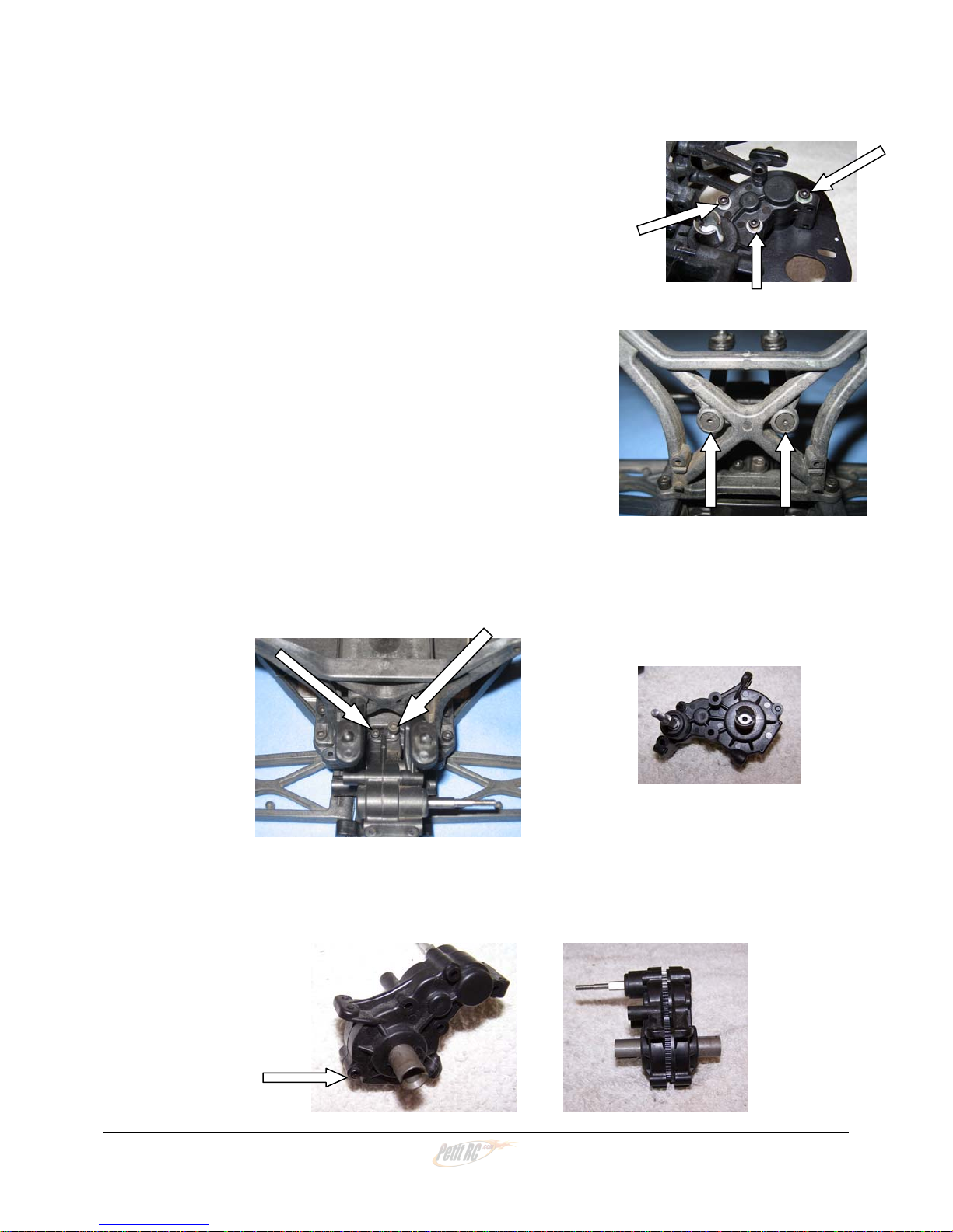
G) To photograph this manual, we assembled the truck several times. In
some photos, parts you have already assembled are “missing.” We
have done this deliberately so you may clearly see this particular step.
Follow the steps in order and you’ll get to the end quickly.
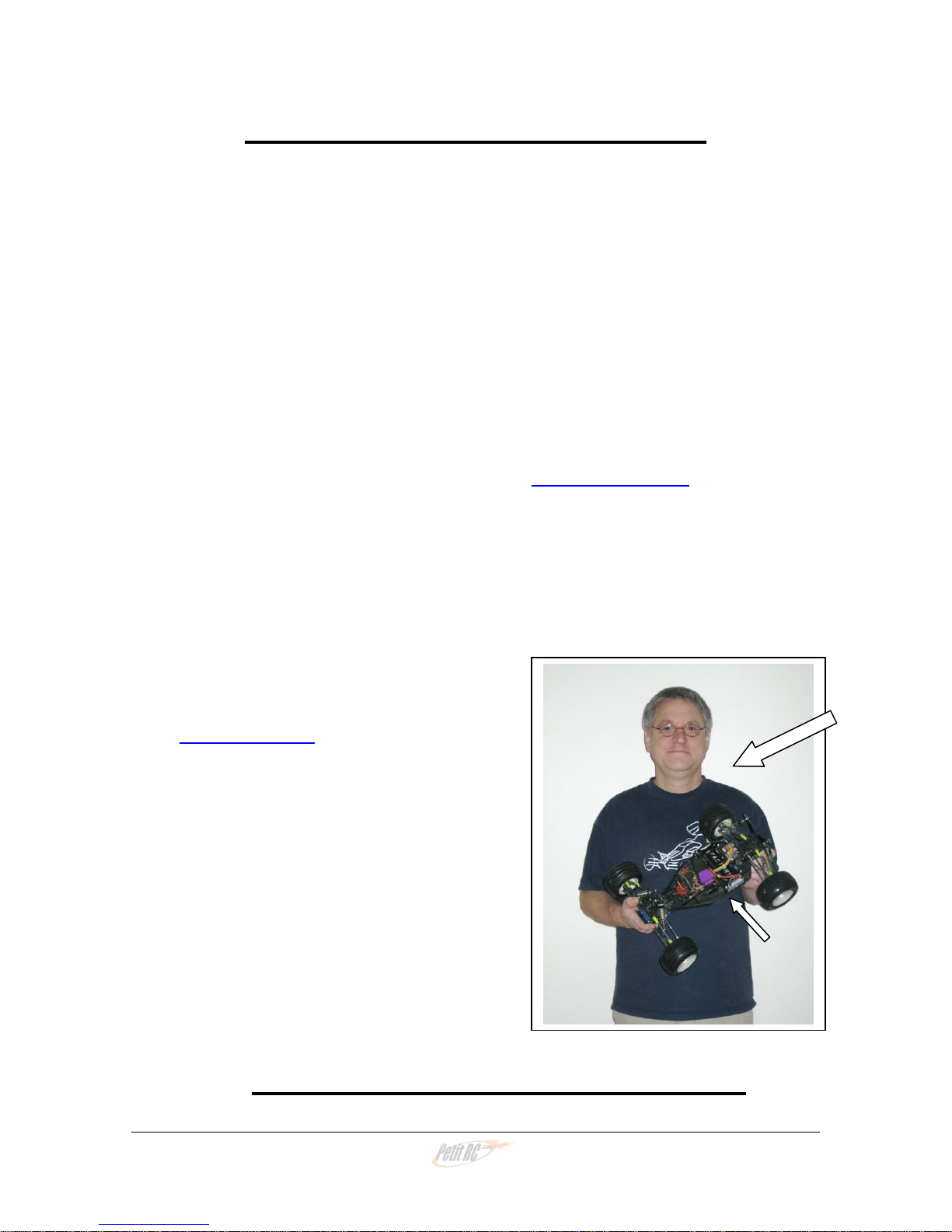
Most important, a big “thank you” to Chris Krieg, father of Team driver Alex,
who assembled his X – 60 at least three times to take the great photos and
wrote many of the instructions. Thank you, Chris!!!

X – 60 Instructions Version 1.0 Page 4
SOME IMPORTANT INFORMATION
This is our third Kit, and we know we are not perfect. If you experience the
slightest difficulty assembling your X – 60, either because a part does not fit
properly or because you have difficulty with the instructions, please contact us
immediately. Even if you figure out what needs to be done, or make a
modification that allows the part to fit, we want to make changes that help the
next person.
You are much more than a customer at X Factory. You have become a member
of a world-wide Family of R/C racing enthusiasts who love working on their cars,
trying new things, and helping others at the track. We communicate with our
Family constantly, and the Family gives us ideas every day for new products and
improvements on existing products. We welcome and encourage this input.
Snail mail: X Factory R/C Racing Products
P.O. Box 2361
Whitehouse, Ohio 43571
Phone: 419-887-1787 (USA)
Thanks in advance for your help!
These instructions are available on our web
site, www.2wdrc.com . The photos are in
color. In many instances, the color photos
on the web are better than the black and
white in this printed manual.
THANK YOU FOR YOUR
CONFIDENCE IN THE X – 60
Photographer and
Instruction-writer
Chris Krieg (Large Arrow)
His X – 60 (Small Arrow)
WELCOME TO THE X FACTORY FAMILY!!

X – 60 Instructions Version 1.0 Page 5
X - 60 INSTRUCTIONS
T4 DISASSEMBLY
FRONT END
1) Remove the body. Save all the body clips for re-use.
Remove the front wheels. Leave the wheel bearings
inside the wheels. Save the wheels and nuts for re-use.
2) Disconnect the servo link from the servo horn. Leave it
connected to the steering bell crank.
3) Remove the two flat head screws from under the chassis that hold the servo in,
and remove the servo. Leave the servo horn and the two servo mounts
attached. Save the two flat head screws that hold the servo in for re-use. Want
to make sure you don’t lose the two screws? Put them a few turns back in the
holes they came from – they’ll be right there later.
4) Remove the two flat head screws that hold on the front
bumper. Take off the bumper. Save it and the two
screws for re-use.

X – 60 Instructions Version 1.0 Page 6
5) Remove the two flat head screws which hold the
bulkhead to the chassis. Save them for re-use.
6) From the top of the truck, remove the center screw
holding the top plate to the post on the T4 chassis.
Save the screw for re-use.
7) Remove the two side top plate screws. Save them for re-use. Carefully remove
the front end and steering assembly, and set it aside for re-use. Make sure the
steering linkage stays in place.
That’s it! Let’s do the rear of the truck.

X – 60 Instructions Version 1.0 Page 7
REAR CVDs & HUB CARRIERS
8) Remove the wheels and tires. Save them and the
nuts for re-use.
9) Remove the two nuts that hold the top of the rear shocks on. Save them for re-
use. Slide the shocks off the bolts, and save the mounting bushings for re-use.
10) Remove the nuts that hold the shock bolts in the
tower. Remove the bolts, and save the bolts, nuts,
bushings and plastic nuts for re-use.
11) Remove the bolt that holds the bottom of each rear shock to the rear control arm.
Set the shocks and bolts aside for re-use. Do not lose the bushing in the bottom
shock eyes.

X – 60 Instructions Version 1.0 Page 8
12) Remove the inner camber link ball cups from their studs. Leave them attached to
the turnbuckle and leave the other end of the link attached to its ball stud at the
hub carrier. Then remove the ball studs. Save the ball studs and any washers
that were under them for re-use.
13) From the outside end of the front of the rear control arm, remove the little 2-56
screw that holds in the hub carrier. Don’t lose it! Now, from the rear of the
control arm, use your wrench to push the hinge pin forward so you can remove
the pin. The hub carrier, with camber link and CVD assembled, will fall off. Save
the spacers. Set all these parts, hub carrier assembly, hinge pin, spacer(s) and
little screw, aside for re-use.
14) Repeat for the other side.

X – 60 Instructions Version 1.0 Page 9
TRANSMISSION
15) Remove the two button head screws that secure the gear
cover. Remove the cover. The cover and screws will
not be needed.
16) Remove the slipper nut, then the spring, slipper plate, slipper pad, spur gear,
inside slipper pad, and inside slipper plate. You will not need the spur gear, but
you must save all the other parts for re-use.
17) From under the truck remove the two flat head screws that hold the motor guard.
Then, from above, remove the two button head screws that hold the motor guard
to the top rear of the transmission. The motor guard and the two button head
screws will not be needed. Save one flat head screw for re-use in B-11.
18) Remove the long bolt through the transmission that
holds the body mounts. This bolt will not be needed.

X – 60 Instructions Version 1.0 Page 10
19) Remove the three bolts that go through the transmission
and hold the motor plate on. Save these bolts for reuse
in A-12; the plate will not be needed.
20) Two flat head screws hold the body mounts on from
the front of the tower. You may remove them and
the mounts if you wish, or just loosen and twist the
mounts out of the way for step 21.
21) From the top, put your wrench down between the body mounts and remove the
two cap head screws that secure the transmission to the shock tower. You
should now be able to remove the transmission from the truck. Save the screws
for re-use in D-2.
22) Remove the bottom bolt that holds together the two halves of the transmission
case and carefully separate the case halves. Save this bolt for re-use in A-10.

X – 60 Instructions Version 1.0 Page 11
23) As the case halves come apart, remove and save all of
the following parts: Top shaft, spacer, and two 3/8 X
3/16 bearings, Idler gear, two more 3/8 X 3/16 bearings,
& idler shaft, Ball differential and two ½ X 5/8 outdrive
bearings. You will need all the parts from inside the
transmission but the two case halves will not be
needed.
That’s it! You have now removed all the parts needed to build your X - 60!

X – 60 Instructions Version 1.0 Page 12
BAG A
TRANSMISSION ASSEMBLY
Let’s do this first because the parts are right in front of us.
CLEAN IT UP!
A1) We suggest you clean and inspect all your T4
transmission parts at this time. You might want to
re-build the diff. If you re-lube the bearings, make
sure the outside is clean and dry so they do not
attract dirt. You need the following items from your
T4: the assembled diff with both outdrive bearings
(6903), the idler gear (9360) with its shaft (9361)
and two 3/16 X 3/8 bearings (6906), and the top
shaft (9601) with its spacer (9602) and two 3/16 X
3/8 bearings (6906).
ASSEMBLE THE X – 6 TRANSMISSION
A2) Remove the transmission case
from Bag A and separate the two
halves. Note the small round ejector
pin bosses on the mounting tabs. You
may wish to file these flat for ease of
installation in the truck.

X – 60 Instructions Version 1.0 Page 13
A3) Install a 3/8 X 3/16 (6906) bearing all
the way into the top shaft boss in the
left transmission case half. The
Team pushes them in with the
shank of an Allen driver or,better yet,
with a socket. See Inst. A5. Install
an outdrive bearing (6903) in its boss.
A4) Make sure the spacer (9602) is on the top shaft (9601) and slide the shaft with
spacer through the bearing in the transmission case.

X – 60 Instructions Version 1.0 Page 14
A5) Gather the idler gear (9360) from your T4, the idler gear from Bag A, the two
3/8 X 3/16 bearings (6906) from your T4 and the two 3/8/ X 3/16 bearings from
Bag A (left photo) Install two bearings in each idler gear, one from each side.
(center) If a bearing is hard to install, we suggest a socket where the OD of the
socket matches the diameter of the outer race of the bearing so you do not push
on the balls or the inner race. (right)
A6) Slide the idler shaft (9361) through the bearings in one idler gear and the idler
shaft from Bag A through the other. Then install the shafts with the two gears
into their bosses in the left transmission case. Be certain to mesh all the gears
properly.
A7) Insert the diff through the outdrivebearing in
the left transmission case half. The head of
the diff screw should be up (arrow). Make
sure all the gears are properly meshed and the
trans rotates freely.

X – 60 Instructions Version 1.0 Page 15
A8) In the right side of the transmission case, insert the remaining 3/8 X 3/16 bearing
(6906) in the top shaft boss and the remaining outdrive bearing (6903) in its
boss. Place a small bead of inexpensive grease around the mating surface of
the right transmission half. This grease only helps keep dirt out, it does not
lubricate anything. Grease attracts dirt; paradoxically this grease is used to seal
out dirt, so be thorough, but don’t use more than is needed. A little touch means
so much.
A9) Some Team drivers put a small amount of AE Stealth Lube on the teeth of their
diff gear to lubricate the transmission. Other Team drivers do not, saying the
trans is freer without the grease. Pay your money and take your pick. Carefully
put the two halves of the transmission together. Make sure everything rotates
very freely. Later is not the time to repair a binding transmission. Wipe excess
grease off the outside of the case.

X – 60 Instructions Version 1.0 Page 16
A10) Install the 4-40 X 3/8” bolt in the corner (short arrow)
and the 4-40 X ½” bolt (from instruction #22) in the rear
center of the transmission (long arrow). Leave them
finger tight until step A12. Make sure the head of the
3/8” bolt is fully down in its boss and no part of the bolt
protrudes on either side. This part of the transmission
must fit into the “box” at the rear of the chassis.
A11) The motor plate has two extra 4-40 tapped holes which are useful to install a fan
for the motor (left photo). The arrows in the right photo point to the three holes
that attach the plate to the transmission. Team drivers put a drop of thread lock
in these holes prior to the next step. Thread lock on the long bolts will come off
going through the transmission, so a drop here works best.
A12) Insert the three 4-40 X 1” screws (from instruction
#19) through the transmission case, threading
them into the motor plate finger tight. Check once
again to ensure the transmission rotates freely but
without excessive slop. This is your last chance!
Now put the final torque on all five transmission
bolts.
OK, transmission’s done now, so let’s set it aside and put on the front end.

X – 60 Instructions Version 1.0 Page 17
FRONT END INSTALLATION
A13) Install two 4-40 X 1 1/4” black flat head screws (short arrows) up from the bottom
of the chassis in the two forward outside battery posts. Install the two stainless
4-40 X 1 ½” flat head screws (long arrows) in the two rear inside battery posts.
These screws go all the way through the four battery hold-down posts and will
secure the battery hold-down strap. It is easiest to do this now and they won’t be
in the way later.
A14) Position the T4 front suspension and steering over the front of the chassis just as
it was on your T4. Be careful that the steering assembly remains in place and
that the bulkhead (9563) stays in position with the top plate (9566). The top plate
should fit snugly over the center post in the chassis and on the bosses at each
side of the front of the chassis.

X – 60 Instructions Version 1.0 Page 18
A15) Secure the top plate with the three screws you took out from the T4. Leave
these screws finger-tight for now.
A16) Carefully turn the chassis & front suspension
over. Install the two 5/8” flat head screws you
removed from the bulkhead back into the
rear-most of the four holes at the front of the
chassis.
A17) Place the front bumper (9562) in position and
secure it with the two 5/8” flat head screws you
took out.

X – 60 Instructions Version 1.0 Page 19
A18) Now secure the three screws for the top plate that you left finger tight in step A14
above
That’s it -- front end is done.

X – 60 Instructions Version 1.0 Page 20
BAG B
BULKHEAD & TRANSMISSION
PREPARATION
B1) Install four ½” threaded inserts in the rear of the chassis from the bottom. Make
sure the hex of each insert seats properly in the chassis. You may have to tap
lightly to fully seat the inserts. The inserts should remain in place through the
transmission install, and it’s easiest to do them now. The rearmost holes in the
chassis will be used later – they do not have hexes for the inserts.
B2) Install the motor plate support bracket using two 4-40 X ¼” flat head screws. The
screws come up from underneath the chassis and thread into the support. Notice
the support is off-set to the left.
Table of contents
Popular Motorized Toy Car manuals by other brands

Redcat Racing
Redcat Racing rampage tt off-road buggy instruction manual

LPR
LPR S10 Twister quick start guide

Mattel
Mattel HotWheels R/C Speed Racer M0661 instructions

Kyosho
Kyosho MINI-Z Racer MR-015 RM Type instruction sheet

Construct A Truck USA
Construct A Truck USA Rascal Assembly instructions

Ofna Racing
Ofna Racing 1/8 SCALE OFF-ROAD BUGGY instruction manual