Xantrex 884-0310-12-01 User manual

Xantrex Lithium-ion Battery
Owner's Guide
Xantrex 310Ah 12V Battery
PN:884-0310-12-01 | 884-0310-12
Xantrex 410Ah 12V Battery
PN:884-0410-12-01 | 884-0410-12
Xantrex 205Ah 24V Battery
PN:884-0205-24-01 | 884-0205-24

Copyright © 2021-23 Xantrex LLC. All Rights Reserved.
All trademarks are owned by Xantrex LLC and its affiliates.
Rebling is a trade name owned by Rebling Power Connectors, America's Power Connection.
Exclusion for Documentation
UNLESS SPECIFICALLY AGREED TO IN WRITING, SELLER
(A) MAKES NO WARRANTY AS TOTHE ACCURACY, SUFFICIENCY OR SUITABILITY OF ANY TECHNICAL OR OTHER
INFORMATION PROVIDED IN ITS MANUALS OR OTHER DOCUMENTATION;
(B) ASSUMES NO RESPONSIBILITY OR LIABILITY FOR LOSSES, DAMAGES, COSTS OR EXPENSES, WHETHER SPECIAL,
DIRECT, INDIRECT, CONSEQUENTIAL OR INCIDENTAL, WHICH MIGHT ARISE OUT OF THE USE OF SUCH INFORMATION.
THE USE OF ANY SUCH INFORMATION WILL BE ENTIRELY AT THE USER’S RISK; AND
(C) REMINDS YOU THAT IF THIS MANUAL IS IN ANY LANGUAGE OTHER THAN ENGLISH, ALTHOUGH STEPS HAVE BEEN
TAKEN TO MAINTAIN THE ACCURACY OF THE TRANSLATION, THE ACCURACY CANNOT BE GUARANTEED. APPROVED
CONTENT IS CONTAINED WITH THE ENGLISH LANGUAGE VERSION WHICH IS POSTED AT http://www.xantrex.com.
NOTE:Visit http://www.xantrex.com , clickProducts, select a Product category, select a Product, and search the Product Documents
panel for a translation of the English guide, if available.
Document Number:975-1044-01-01 Rev H Date: April 2023
Product Name and Part Number
Xantrex 310Ah 12V Battery (884-0310-12-01 | 884-0310-12)
Xantrex 410Ah 12V Battery (884-0410-12-01 | 884-0410-12)
Xantrex 205Ah 24V Battery (884-0205-24-01 | 884-0205-24)
Contact Information
Telephone: +1-800-670-0707 / +1-408-987-6030
Email: https://xantrex.com/support/get-customer-support/
Web: http://www.xantrex.com
Information About Your System
As soon as you open your product, record the following information and be sure to keep your proof of
purchase.
Serial Number ____________________________
Product Number ____________________________
Purchased From ____________________________
Purchase Date ____________________________

975-1044-01-01 3
Purpose
The purpose of this Owner's Guide is to provide explanations
and procedures for installing, operating, configuring,
maintaining, and troubleshooting a Xantrex Lithium-ion Battery
for Recreational, Commercial and Fleet Vehicle, or Marine
installations.
Scope
The guide provides safety and operating guidelines as well as
information on installing and configuring the lithium-ion battery
using the Xantrex App.
Audience
The guide is intended for qualified personnel.
Qualified personnel have training, knowledge, and experience
in:
lInstalling electrical equipment.
lApplying all applicable installation codes.
lAnalyzing and reducing the hazards involved in performing
electrical work.
lInstalling and configuring batteries (especially lithium-ion
batteries, as applicable)
lSelecting and using Personal Protective Equipment (PPE)
and following safety work code practices. See NFPA 70E
or CSA Z462.
Abbreviations and Acronyms
A Amperes
Ah Amp-hours (a unit of battery capacity)
AC Alternating Current[V]
AGM Absorbed Glass Mat (a battery type)
BLE Bluetooth Low Energy
BMS Battery Management System
BTS Battery Temperature Sensor
DC Direct Current[Z]
h Hours (a unit of time)
Hz Hertz (a unit of frequency)
in-lb inch-pound force (a unit of torque)
kW Kilowatts (1000 watts)
LED Light Emitting Diode
LFP LiFePO4(lithium iron phosphate – a battery type)
m Minutes (a unit of time)
max Maximum
min Minimum
ms Milliseconds (a unit of time)
N-m Newton-meters (a unit of torque)
PN Product Number
PPE Personal Protective Equipment
s Seconds (a unit of time)
SOC, SoC State-of-Charge of battery
V, VAC, VDC Voltage, Volts AC, Volts DC
W Wattage, watt (a unit of power)
° Degrees symbol commonly used for temperature
°C Unit of degrees in Celsius scale
°F Unit of degrees in Fahrenheit scale
% Percent, percentage
Related Information
You can find more information about Xantrex products and
services at http://www.xantrex.com.

4 Xantrex Lithium-ion Battery Owner's Guide
Important Safety Information
READ AND SAVE THIS OWNER'SGUIDE FOR FUTURE
REFERENCE.
This guide contains important safety instructions for the Xantrex
Battery that must be followed during installing, operating,
configuring, maintaining, and troubleshooting.
Read these instructions carefully and look at the equipment to
become familiar with the device before installing, operating,
configuring, maintaining, and troubleshooting it. The following
special messages may appear throughout this documentation or
on the equipment to warn of potential hazards or to call attention
to information that clarifies or simplifies a procedure.
The addition of either symbol to a “Danger” or
“Warning” safety label indicates that an electrical
hazard exists which will result in personal injury if the
instructions are not followed.
This is the safety alert symbol. It is used to alert you
to potential personal injury hazards. Obey all safety
messages that follow this symbol to avoid possible
injury or death.
DANGER
DANGER indicates a hazardous situation which, if not avoided, will result in
death or serious injury.
WARNING
WARNINGindicates a hazardous situation which, if not avoided, could
result in death or serious injury.
CAUTION
CAUTION indicates a hazardous situation which, if not avoided, could
result in minor or moderate injury.
NOTICE
NOTICE is used to addresspractices not related to physical injury.
Please Note
No responsibility is assumed by Xantrex for any consequences
arising out of the use of this material.
DANGER
HAZARD OF ELECTRIC SHOCK,
EXPLOSION, BURN, OR ARC
FLASH
ARC FLASH
HAZARD
cAn example of an arc flash event
could be a direct short circuit caused
by a metallic object such as a tool
bridging between the positive and
negative of an energized circuit.
nThis battery shall be installed and serviced only by
qualified personnel.
nAlways wear proper PPE (safety glasses and clothing)
when working on the Li-ion battery and follow safe
electrical work practices according to local codes.
nDo not wear metallic items such as watches or bracelets
when working on the battery. Use insulated tools to
prevent accidental short circuit.
nDo not install the Li-ion battery module adjacent to any
heat source. Keep away from sources of ignition.
nDo not install or operate any of the system devices in a
compartment containing flammable materials or in
locations that require ignition-protected equipment.
nDo not use in vital, medical, or life-support applications.
nNo user-serviceable parts. Do not attempt to open or
dismantle the Li-ion battery. If the battery module is
damaged, do not touch the toxic electrolyte or powder,
and consult your dealer.
nWhen the battery module is damaged, it can release
harmful gases. Ensure the surrounding environment is
well-ventilated.
nIn case battery content comes in contact with skin or eyes,
immediately flush the affected area with large amount of
clean water and seek medical help.
nIn case of fire, use only a Class ABC (dry chemical) or
CO2type fire extinguisher. Water can be a dangerous
extinguishing medium for energized equipment because
of the risk of electric shock.
nDispose of Li-ion batteries through a local recycling
center. Do not mix batteries with other wastes. Contact
your local recycling center for proper disposal
information.
nDo not crush, puncture, drop, disassemble, or dispose of
in fire.
Failure to follow these instructions will result in death or
serious injury.
WARNING
HAZARD OF FIRE, ELECTRIC SHOCK, EXPLOSION,
AND PERSONAL INJURY
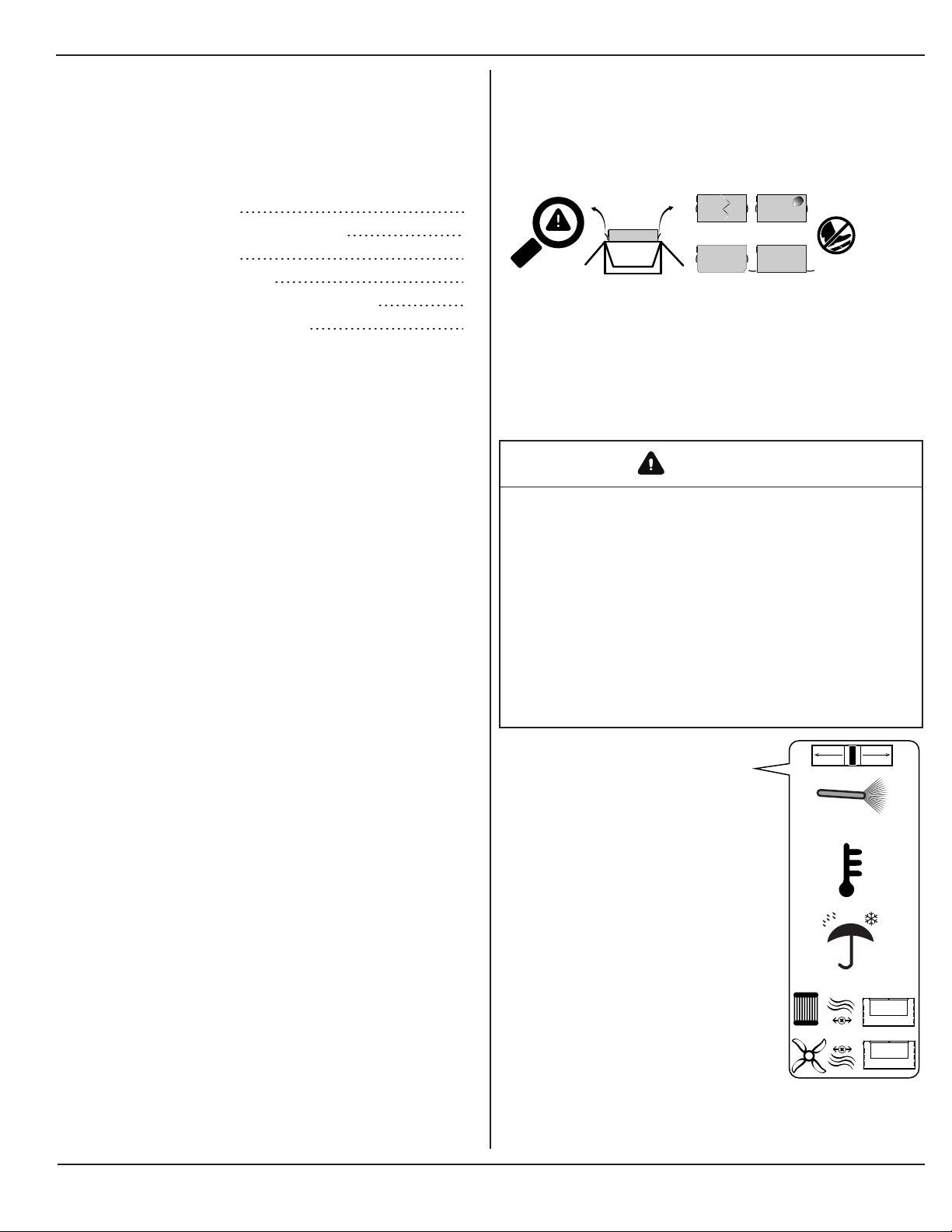
nDo not expose the Li-ion battery to rain, snow, or liquids of
any type. Products are designed for indoor use only.
nDo not step on the battery module.
nAlways use proper lifting techniques when handling the
battery module. Battery is heavy.
nDo not charge the battery in ambient temperature below
freezing.
nDo not disconnect the battery while it is being charged.
Failure to follow these instructions can result in death, serious
injury, or equipment damage.

975-1044-01-01 5
NOTICE
RISK OF EQUIPMENT DAMAGE
nDo not allow the battery to be depleted.
nCharge the battery module with an approved charger.
Contact Xantrex for details.
nDo not charge the battery above the recommended
voltage.
Failure to follow these instructions can result in damage to
equipment and may void the warranty.
BATTERY DISPOSAL
At the end of the battery’s useful life, proper disposal is required.
Do not dispose the battery with ordinary household waste. Refer
to your local codes for proper disposal of lithium-ion batteries.
Regulatory Information
This device complies with Part 15 of the FCC Rules and
contains a license-exempt transceiver. These limits are
designed to provide reasonable protection against harmful
interference in a residential environment. This equipment
generates, uses, and can radiate radio frequency energy and, if
not installed and used in accordance with the instructions, may
cause harmful interference to radio communications.
However, there is no guarantee that interference will not occur
in a particular installation. If this equipment does cause harmful
interference to radio or television reception, which can be
determined by turning the equipment off and on, the user is
encouraged to try to correct the interference by one or more of
the following measures:
nReorient or relocate the receiving antenna.
nIncrease the separation between the equipment and
receiver.
nConnect the equipment into an outlet on a circuit different
from that to which the receiver is connected.
nConsult the dealer or an experienced radio/TV technician
for help.
FCC ID: [2AXM8-JDY-23]
RF EXPOSURE
The device has been evaluated to meet general RF exposure
requirements. The device can be used in portable exposure
condition without restriction.
CAUTION
Unauthorized changes or modifications to the equipment could
void the user’s authority to operate the equipment.

6 Xantrex Lithium-ion Battery Owner's Guide
Contents
Important Safety Information 4
Regulatory Information 5
Materials List 7
Before You Begin 7
Installation Tools and Materials 8
Installation Codes 8
Pre-Installation Checklist 9
1.0 Checking the Battery 9
2.0 Choosing a Location for the Battery 9
3.0 Mounting the Battery 10
4.0 Placing the Battery Safely 11
5.0 Installing DC Protections for the Battery 11
6.0 Connecting the Battery Cables 12
Parallel Installation 13
Parallel Installation Steps 14
Communication Installation 17
Deutsch Connector Pin Designations 17
Operation 19
BMS(Battery Management System) Features 19
The Xantrex App 19
BMSOperations 21
Power Button 21
Cold Ambient Temperature Operation 21
Hot Ambient Temperature Operation 21
Xtend Mode 21
Troubleshooting and Maintenance 23
Pre-service Checklist 24
Troubleshooting 25
Interpreting Ring LED Patterns on the Battery 27
Battery Maintenance Guideline 28
Battery Storage Guidelines 28
Storage Instructions for Short Durations 28
Storage and Maintenance Instructions for Long
Durations 28
Specifications 29
Electrical and Physical Specifications 30
Regulatory Approvals 30

Materials List
975-1044-01-01 7
Introduction
The Xantrex Lithium-ion Batteries are lithium iron phosphate
(LiFePO4) chemistry batteries used in conjunction with the
internal Battery Management System (BMS) unit which protects
the batteries and monitors state-of-charge (SOC), voltage,
current, and temperature.
Figure 1 Typical System
Lithium-ion
Battery Pack
BMS
POWER SYSTEM
This guide provides instructions on how to safely install,
operate, and maintain your Xantrex battery system.
Materials List 7
Before You Begin 7
Installation Tools and Materials 8
Installation Codes 8
Materials List
The Xantrex Battery base package includes the following items.
A B C
Figure 2 Materials List
A Xantrex Battery
B Quickstart guide
C Rebling connector
NOTE: If any of the items are missing, contact Xantrex or any
authorized Xantrex dealer for replacement.
IMPORTANT: Keep the carton and packing material in case
you need to return the lithium-ion battery for servicing. The
battery requires special packaging and handling due to the
nature of the product.
Before You Begin
Before beginning your installation:
nRead this entire Installation guide so you can plan the
installation from beginning to end.
nAssemble all the tools and materials you require for the
installation.
nReview the Safety Information on page 4.
nBe aware of all safety and electrical codes which must be
met.
WARNING
ELECTRICAL SHOCK AND FIRE HAZARD
nAll wiring should be done by qualified personnel to ensure
compliance with all applicable installation codes and
regulations.
nDisable and secure all DC disconnect devices and
automatic generator starting devices.
nDo not mount in a zero-clearance compartment.
Failure to follow these instructions can result in death, serious
injury, or equipment damage

Installation Tools and Materials
8 Xantrex Lithium-ion Battery Owner's Guide
Installation Tools and Materials
You will need the following to install the Xantrex Battery:
nTorque wrench
nMultimeter
nPPE
nWire stripper
nCrimping tool
IMPORTANT: A torque wrench is required for correct
installation of the batteries. A proper torque of 60±3in-lb (or
6.7±0.35N-m) is required for correct installation. If too little
torque is applied to the electrical connection hardware, it could
come loose during transportation or operation of the batteries. If
too much torque is applied the hardware could damage the
Rebling connector.
Installation Codes
Governing installation codes vary depending on the specific
location and application of the installation. Some examples
include the following:
nThe U.S. National Electrical Code (NEC)
nThe Canadian Electrical Code (CEC)
nThe U.S. Code of Federal Regulations (CFRs)
nCanadian Standards Association/CSA Group (CSA) and
the RV Industry Association (RVIA) standards and codes
for installations in RVs
nThe American Boat and Yacht Council (ABYC) standards
and US Coast Guard Regulations (33CFR183, Sub Part I)
for Marine installations in the U.S.
It is the installer’s responsibility to ensure that all applicable
installation requirements are met.

1.0 Checking the Battery
975-1044-01-01 9
Pre-Installation Checklist
This section provides a list of pre-installation information about
where to install the battery and what protective devices are
needed. For your convenience, the checklist is divided into
these main points:
1.0 Checking the Battery 9
2.0 Choosing a Location for the Battery 9
3.0 Mounting the Battery 10
4.0 Placing the Battery Safely 11
5.0 Installing DC Protections for the Battery 11
6.0 Connecting the Battery Cables 12
1.0 Checking the Battery
Check the battery, included hardware and the box for visible
damage including cracks, dents, chips, and deformations.
Ensure that the battery including its components are labeled.
Check Materials List on page 7.
Figure 3 Inspecting the battery
IMPORTANT: Contact Xantrex Technical Support immediately
if you see visible damages to the battery at +1-800-670-0707 or
by email at customerservice@xantrex.com.
2.0 Choosing a Location for the
Battery
WARNING
FIRE AND EXPLOSION HAZARDS
lDo not install the Xantrex Battery in compartments
containing flammable materials, or in locations that
require ignition-protected equipment. This includes any
space containing gasoline-powered machinery, fuel
tanks, or joints, fittings, or other connections between
components of the fuel system. This equipment contains
components that tend to produce arcs or sparks.
lDo not cover or obstruct the ventilation openings.
lDo not install the Xantrex Battery in a zero-clearance
compartment. Overheating may result.
Failure to follow these instructions can result in death, serious
injury, or equipment damage.
Select a location for the battery that is
stable, clean, cool, dry, and well-
ventilated.
nMaintain an ideal operating
ambient temperature range of
59to77°F (15to25°C).
Temperatures below this range
can reduce system
performance. Temperatures
above this range can reduce
battery cell life and reduce
system performance.
nHaving a nearby heat source
can cause premature wear on
the cells inside and earlier
disconnects during charge and
discharge scenarios where the
battery produces some heat
internally.
nHaving a cooling source
pointed at the battery can
reduce ideal charging
scenarios where the battery
should ideally be warmer.
IP20
59
77
15
25
ºF ºC

3.0 Mounting the Battery
10 Xantrex Lithium-ion Battery Owner's Guide
Map out the location of your batteries
with a simple wire diagram for pre-
planning purposes. The cables
between the batteries and all other
components should be as short as
possible. Having shorter cables will
reduce the voltage drop throughout
the system allowing better
performance and reliability of your
power system.
cIn a parallel installation, the
battery cables between the parallel
batteries must be the same length to
reduce voltage differences between
the batteries.
nInclude all the components on
your wire diagram, specifically
DC protection devices and
major connection points.
nAlso take into consideration
where the other components
will be installed in relation to
the batteries to account for
cable bending as well as ease
of access to components once
they are installed
3.0 Mounting the Battery
WARNING
HEAVY EQUIPMENT
Always use proper lifting techniques during handling and
installation. A two-person lift may be required to prevent personal
injury.
Failure to follow these instructions can result in death, serious
injury, or equipment damage
To mount the Xantrex Battery:
1. Select an appropriate mounting location inside your
vehicle or vessel.
2. Mount the battery upright (top label pointing up as shown
in the cover page).
a. On a horizontal surface such as the floor (ideal)
b. On a horizontal surface on battery racks
3. Alternatively, you can mount sideways with the side label
pointing up.
4. Ensure that the battery is secured according to local
regulations. For securing a marine battery according to
local regulations, refer to 33CFR 183.420 and ABYC E-10
- 10.7. For securing an RV battery according to local
regulations, refer to ANSI-RVIA LV standard clause 2-3.
Figure 4 Approved Orientations
NOTICE
GENERAL PRECAUTION
Do not mount the Xantrex Battery in an area subject to high
vibration or physical shock.
Failure to follow these instructions may reduce the life of the
battery.

4.0 Placing the Battery Safely
975-1044-01-01 11
4.0 Placing the Battery Safely
Position the battery and devices that will connect to the battery
in a way that the battery cables avoid sharp bends. Follow the
bend radius recommendation below. Aside from battery cables,
it is good practice to apply the same bend radius to
communication cables as well.
Figure 5 Bending Radius
TIPS:
nA cable’s bend radius should be no less than eight (8)
times the outside diameter of the cable used. More
specific details can be supplied by the cable and wire
manufacturer for your specific scenario.
nAs it is not normally possible to have such a large bend
radius in many installations due to limited space, getting
as large a bend radius in as much as the space allows is
ideal.
5.0 Installing DC Protections
for the Battery
Battery protection devices such as properly rated DC fuses,
DCdisconnect devices, or DC breakers are required to protect
the battery from overcurrent scenarios. Here are some basic
definitions:
n(A) DC fuses are fuses specifically rated for DC and
come with their own fuseholders. Fuses are replaced
when they blow. Fuses are installed together with a DC
disconnect device. See Figure 6 below.
n(B) DC disconnect devices are binary switches that are
either open (OFF) or closed (ON) to stop or allow DC
current to flow, respectively.
n(C) DCcircuit breakers or simply DCbreakers are arc-
reducing electromechanical switches that trip (open fast)
with overcurrent and are reset (closed) manually. See
Figure 7 below.
A B C
IMPORTANT:
nThe battery protection device should be installed inline
with the positive cable of the battery.
nIdeally the protection device should be installed as close
as practicably possible to the positive terminals of the
battery.
ncDo not manually operate these protection devices
while there are active DCloads and/or charging devices
connected to the DC bus. For example, an engine
mounted alternator that is connected to the DC bus may
sustain damage if the protection devices are closed and
opened while in operation. Turn off the engine first.
Figure 6 DC fuse and DC disconnect
Figure 7 DC breaker

6.0 Connecting the Battery Cables
12 Xantrex Lithium-ion Battery Owner's Guide
6.0 Connecting the Battery
Cables
WARNING
FIRE HAZARD
Use only stranded, copper wire rated minimum 75 °C (105 °C for
marine installations). Make sure all DC connections to the
Rebling connector terminals (see Figure 9 below) are tight to a
torque of 60±3in-lb (or 6.7±0.35N-m) of force. Loose
connections will overheat. Too much torque may crack the
Rebling connector terminals.
Failure to follow these instructions can result in death, serious
injury, or equipment damage.
NOTICE
REVERSE POLARITY
nCheck cable polarity at the Xantrex Battery before making
the final DC connection. Positive must be connected to
positive; negative must be connected to negative.
nReversing the positive and negative battery cables will
blow a fuse in the Xantrex Battery and void your warranty.
Failure to follow these instructions can result in equipment
damage.
To secure the battery cable to the battery terminal using
the Rebling connector:
1. Make sure the battery is turned off. See Power Button on
page 21 for instructions on how to operate the Power push
button.
nEnsure all other DC sources have been powered off
and disconnected. cIf a charging source is
present, operational, and connected to a common
bus with the battery, the battery unit will not power
down.
nDisconnect the 12-pin Deutsch connector from the
battery.
2. Attach using a 5/16" (or 3/8") single hole lug, the negative
(-) battery cable to the negative (-) battery terminal of the
cable-mounted keyable plug. Review Figure 9 for proper
routing including feeding the cables through the boot and
stacking the terminal hardware. Tighten the bolt to 60±3in-
lb (or 6.7±0.35N-m).
3. Install your DC-rated circuit protection device (Figure 9 )
in line with the positive battery cables. The device MUST
be in open position.
IMPORTANT: Postpone this step if you are planning a
parallel battery installation. See Parallel Installation Steps
on page 14.
4. Attach the protected positive (+) battery cable to the
positive (+) battery terminal of the cable-mounted keyable
plug. Review Figure 9 for proper routing including feeding
the cables through the boot and stacking the terminal
hardware. Tighten the bolt to 60±3in-lb (or 6.7±0.35N-m).
5. Reassemble the cable-mounted keyable plug by
encapsulating the key assembly with the top and boot.
6. Remove the red screw tip cover from the key screw.
7. Align the connector to its mate on the battery and turn the
key lever clockwise to fasten the connection until the lever
stops. Do not apply excessive force.
IMPORTANT: Postpone this step if you are planning a
parallel battery installation. See Parallel Installation Steps
on page 14.
Figure 8 Cable-mounted keyable plug
AB
TIP: Separate the top(A) from the boot(B) as shown to expose the
key assembly which contains the battery terminals.
NOTE: The cable-mounted keyable plug doubles as a protective
boot that securely attaches the battery cables as an assembly to
the battery terminals.
Figure 9 Rebling Assembly
C
D
E
A
F
B
A battery cable
B terminal bolt
C lock washer
D cable ring lug
E Rebling connector terminal
F DC-rated circuit protection device e.g. battery breaker

Parallel Installation Steps
14 Xantrex Lithium-ion Battery Owner's Guide
Parallel Installation Steps
IMPORTANT:
nBatteries must be of the same make, model, and age for all batteries connected in parallel.
nBefore connecting batteries together, verify independently using a multimeter that each battery is charged to 100% SoC. The
open terminal voltage should be within 0.05VDC of each other at the point of connection. This procedure helps ensure that
there is minimal current flow and sparking between batteries. Note that you can also use the Xantrex App to provide a reading
of SoC information. Nevertheless, a voltage measurement using a multimeter must be taken to ensure there is as little
voltage between the terminals as possible.
NOTICE
EQUIPMENT DAMAGE
Do not connect batteries in series.
Failure to follow these instructions can result in equipment damage.
Figure 10 Parallel batteries
PARALLEL
=
YES
SERIES
=
NO
This is for illustration purposes only.
NOTE: Keep the cables between batteries and ground cables the same lengths
for optimal performance and to ensure equal discharging and charging.
How to connect batteries in parallel:
WARNING
FIRE HAZARD
Make sure all DC connections to the common positive bus terminals are torqued according to the bus terminal manufacturer's torque
specifications. Loose connections will overheat. Too much torque may damage the terminals.
Failure to follow these instructions can result in death, serious injury, or equipment damage.
1. Ensure that DC protection device (such as a DC fuse and disconnect or a DC breaker) is opened or disconnected before
starting.
2. Turn OFF all batteries using the power push button on the battery.
3. Install and secure the new batteries in their location.
NOTE: With the locations ensure as minimal length, joints, and size variation is made between the cables connecting the
terminals of the batteries.
4. Attach the battery cables to the first Rebling connector as instructed in
the previous section. Do the same for the second Rebling connector.
5. Connect the battery positive cable end from the first Rebling connector
to the common positive bus.

Parallel Installation Steps
975-1044-01-01 15
6. Then connect the battery positive cable from the second Rebling
connector to the common positive bus.
NOTE: If more than two batteries are being connected, ensure a
consistent connection method is used for connecting the batteries.
7. Connect the battery negative terminal from the first Rebling connector to
the common negative bus.
8. Then connect the negative positive cable from the second Rebling
connector to the common negative bus.
NOTE: If more than two batteries are being connected, ensure a
consistent connection method is used for connecting the batteries.
9. Install your DC-rated circuit protection device in line with the common
positive bus.
NOTE: In parallel installations, one DC-rated protection device may
protect only two batteries as shown. In the case of a third or fourth
battery, a second protection device must be installed.
10. Connect the final connection cables from the common negative bus to
its termination point on the charging device and from the remaining
positive terminal of the DC-rated circuit protection device to its
termination point on the charging device.
11. Attach the cable-mounted keyable plug to the battery terminals of the
first battery by turning the key lever clockwise. Do the same for the
second battery.
12. Double check all connections for any reverse wiring or incorrectly connected batteries.
13. Ensure all battery terminals are torqued correctly according to specifications.
NOTE: Double check all your wiring between batteries for any reversed cables. Check the DC protection device/s for the
correct polarity as well.
14. Turn ON all the batteries using the power push button on the battery.
NOTE: Wait for all batteries to be fully turned on before proceeding to connect to the main system by closing the DC
disconnect or DC breaker. You may observe that when one battery is turned on, other connected batteries will be
activated as well.

This page is intentionally left blank. [1]

Deutsch Connector Pin Designations
975-1044-01-01 17
Communication Installation
This section contains instructions for other functions that can be
used in vehicle systems providing additional performance and
usage scenarios. These functions need to be connected through
the 12-Pin Deutsch connector. This sections contains the
following topics:
Deutsch Connector Pin Designations 17
Deutsch Connector Pin
Designations
The pins should only be connected to devices on an as-needed
basis. The Xantrex Battery will function without having the
communication ports externally connected to the battery.
The Deutsch connector harness is available using product code
(PN: 881-0262-12-02). Contact Xantrex or your Xantrex dealer
to order.
Figure 11 Deutsch connector harness
7
12 6
1
NOTICE
EQUIPMENT DAMAGE
Incorrect wiring and pin assignments may lead to equipment
malfunction and/or damage.
Failure to follow these instructions can result in equipment
damage.
Pin# Color Function
Signal
12 or 24 V
nominal
according to
model
Feature Description
1 Red Engine Running
Input Input High
(12/24V) •Turn the battery from OFF to ON state.
•If the internal contactor is closed then it shall wait two
seconds before Pin 2 shall go high. (If the signal to Pin 1
is removed, Pin 2 shall also drop immediately.)
2 Orange Alternator
Activation Output
(FCC Enable)
Output
High
(12/24V)
If the internal contactor is closed and the battery pack
needs to open it (due to a fault), the BMS will set the
Alternator Activation output low (0V) to turn off the
alternator, wait two seconds, and then open the internal
contactor.
3 Grey Push button wire 1
out (power) Signal
(12V,
10mA)
Push Button wire 1 (momentary switch)
cThis wire is to be utilized for the Remote Push-button
Supply ONLY.
4 Grey Push button wire 2
in (return) Return Push button wire 2 (momentary switch)
Power on this pin for certain times and sequences can
perform the following actions:
•Power the Unit ON
•Power the Unit OFF
•Enter Maintenance Mode
•Clear Faults
•Other Maintenance Features.
5 Black LED output Output
(12/24V) On/Off LED output
6 Black LED return Return Common return for remote on/off LEDs
7 White CAN High COMM CAN/RV-C High
8 Blue CAN Low COMM CAN/RV-C Low
9 Black Low SOC
alarm/Intelligent
Generator Start
Output
(12/24V) Low SOC alarm:
This pin will pulse a high signal for one (1) second every
twenty (20) seconds when the battery 21% > SOC
>11%. The pin will pulse for one (1) second every five
(5) seconds when the battery SOC = 11%. The pin will
be held high when the SOC < 10%.
Intelligent Generator Start:
The intelligent generator start option is only configurable
using the SOC gauge (881-0268-01). Default operation is
when the battery SOC < 20% the signal shall go high
until the SOC >80% of the battery. These thresholds can
be changed using the SOC display.
Table 1 Pin reference guide

18 Xantrex Lithium-ion Battery Owner's Guide
Pin# Color Function
Signal
12 or 24 V
nominal
according to
model
Feature Description
10 Violet Charge
Percentage
(control of
voltage)
Output
PWM Working in conjunction with Pins 1 and 2. When the
engine running signal is detected high and pin 2 has
enabled the alternator this pin shall produce a control
signal that is compatible with Xantrex Alternators.
11 Brown Contactor
state/Aux output Output
(12/24V) High signal when contactor is closed
12 Yellow Shore Charge
Signal input Input High
(12/24V) •Turn the battery from OFF state to ON state.
•Activates the internal heater and logic in cold
environments.
•Indicate to the battery that shore power is present on the
DC Bus.
Figure 12 Battery Deutsch connector receptacle
1 2 3 4 5 6
7 8 9 10 11 12
12 7
61

BMS(Battery Management System) Features
975-1044-01-01 19
Operation
This section includes descriptions of the different modes and
settings of the Xantrex Lithium-ion Battery. This section
includes:
BMS(Battery Management System) Features 19
The Xantrex App 19
BMSOperations 21
Power Button 21
Cold Ambient Temperature Operation 21
Hot Ambient Temperature Operation 21
Xtend Mode 21
BMS(Battery Management
System) Features
Figure 13 Xantrex App Home screen
The Xantrex App
The battery has a built in BLE (Bluetooth Low Energy ) module
for basic communication and troubleshooting with the battery.
The BLE module app (the Xantrex App) can be found by
scanning the QR code on the battery or searching for "Xantrex
App" on the Play Store or the App Store respectively.

20 Xantrex Lithium-ion Battery Owner's Guide
Monitor
Figure 14 Monitor tab
Setting Description
State of
Charge
Measure of the internal amount of charge in the battery
Voltage The internal voltage of the battery pack
Current The amount of current flowing through the BMS. (-)
Value is a discharge of the battery, (+) Value is a
recharge current.
Power The amount of power flowing through the BMS. (-) Value
is a discharge, (+) Value is recharge.
Batt.
Temp
The temperature of the cells inside of the battery.
Overview
Figure 15 Overview tab
Setting Description
Device Model Name Unique hardware ID
Product Serial Number The serial number of the battery
Hardware Version Internal revision of the battery
Software Version Software revision of the BMS.
Xantrex App Version The revision of the application
Alerts
The Xantrex App will highlight any event that is detected in the
battery or the BMS. The alert will also display a suggestion for
correcting the detected event. See Troubleshooting on page 25.
Summary LED Indicator
nON < 30 Seconds : 100% brightness
nON > 30 Seconds : 10% brightness (reduced light for
comfort)
nEvent/Error: Defined by related flash pattern
Pressing the button will return LED to 100% brightness. The
same will happen when an event or error is detected.
This manual suits for next models
5
Table of contents
Other Xantrex Camera Accessories manuals