manuals.online logo
Brands
  1. Home
  2. •
  3. Brands
  4. •
  5. Manfrotto
  6. •
  7. Camera Accessories
  8. •
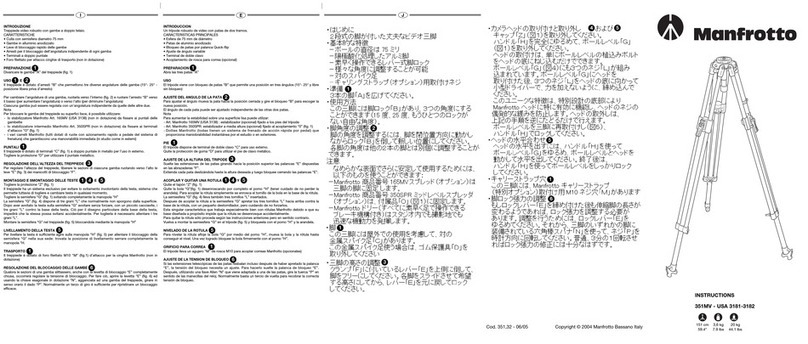
  9. Manfrotto 350MV User manual

Manfrotto 350MV User manual

J
E
I
INTRODUCCION
Un trípode robusto de video con patas de dos tramos.
CARACTERISTICAS PRINCIPALES
• Esfera de 100 mm de diámetro
• Patas de aluminio anodizado
• Bloqueo de patas por palanca Quick-flip
• Ajuste de ángulo variable
• Terminal de doble clavo(versión 350 MV)
• Terminal de goma con pincho retractil (versión 350)
• Acoplamiento de rosca para correa (opcional)
PREPARACION
Desbloquee cada uno de los clips “B”. Abra las 3 patas “A” hasta que lleguen a su posición
final. El trípde viene provisto de bloqueos “V” que permiten bien un ángulo de 20° o bien
posición libre.
USO
AJUSTE DEL ANGULO DE LAS PATAS
Para ajustar el ángulo de las patas muévalas hacia la posición cerrada y presione el bloqueo
“V” hacia abajo (véase el indice rojo). Ello permite ahora el libre movimiento de la pata.
El ángulo de cada pata puede ser ajustado de forma independiente de las otras dos patas.
Nota: Para aumentar la estabilidad sobre una superficie lisa puede utilizar:
- Art. Manfrotto 165MV (USA 3138): estabilizador (opcional) fijado a los pies del trípode
350MV (USA 3190-3193)
- Art. Manfrotto 165 (USA 3155): estabilazador (optional) fijado a los pies del trípode 350
(USA 3191-3192)
- Art. Manfrotto 350SPR: estabilizador a media altura (opcional) fijado al acoplamiento “0”
(fig. 1)
- Dollies Manfrotto (todas tienen un sistema de frenado de acción rápida por pedal) que
proporciona maniobrabilidad instantánea por el estudio o en exteriores.
PIE
Versión 350MV
El trípode dispone de terminal de doble clavo “C” para uso externo.
Quite la protección de goma “D” para utilizar el pie de clavo metálico.
Versión 350
El trípode dispone de terminales de goma “Q” con pinchos retractiles “R” para el uso en
exteriores. Con el fin de sacar el pincho metálico “R” presione la palanca “S” y gire en la
ranura “T”.
AJUSTE DE LA ALTURA DEL TRIPODE
Suelte las extensiones de las patas girando hacia la posición superior las palancas “E”
dispuestas en las abrazaderas “F”. Extienda cada pata deslizándola hasta la altura deseada
y luego bloquee cerrando las palancas “E”.
ACOPLAR Y QUITAR UNA ROTULA Y
Quite el tapón “Z” (fig. 1). Quite la bola “G”(fig. 1) desenroscando por completo el pomo “H”
(tener cuidado de no perder la arandela).Para acoplar la rótula simplemente se enrosca el
tornillo de la bola en la base de la rótula. La semiesfera “G” (fig. 4) lleva también tres
tornillos “L” insertados.
Despues de acoplar la rótula a la semiesfera “G” apretar los tres tornillos “L” hacia arriba
contra la base de la rótula, con un pequeño destornillador, pero cuidando de no forzarlos.
Esta singular característica que trabaja especialmente bien con rótulas Manfrotto debido a
que su base diseñada a propósito impide que la rótula se desenrosque accidentalmente.
Para quitar la rótula sólo proceda según las instrucciones anteriores pero en sentido
contrario. Vuelva a montar la semiesfera “G” en el trípode (fig. 5) y bloqueela con el pomo
“H” y la arandela.
NIVELADO DE LA ROTULA
Para nivelar la rótula afloje la bola “G” por medio del pomo “H”, mueva la bola y la rótula
hasta conseguir el nivel. Una vez logrado bloquee la bola firmemente con el pomo “H”.
ORIFICIO PARA CORREA
El trípode lleva un agujero “M” de rosca M10 para acoplar correas Manfrotto (opcionales)
AJUSTE DE LA TENSION DEL BLOQUE DE PATAS
Si las extensiones telescópicas de las patas resbalan aún despues de apretar la palanca
“E”, la tensión del bloqueo precisa un ajuste. Para hacerlo suelte la palanca “E”. Después,
con una llave Allen “N” (viene acoplada a una de las patas) gire el tornillo “P” en el sentido
de las manecillas del reloj. Normalmente un tercio de vuelta será suficiente para recobrar la
correcta tensión de bloqueo.
INTRODUZIONE
Treppiede video robusto con gambe a doppio telaio
CARATTERISTICHE
• Culla con semisfera diametro 100 mm
• Gambe in alluminio anodizzato
• Leve di bloccaggio rapido delle gambe
• Arresti per bloccaggio dell’angolatura indipendente di ogni gamba
• Terminali a doppio puntale (versione 350MV)
• Terminali in gomma con puntale metallico retrattile (versione 350)
• Foro per attacco cinghie di trasporto (non in dotazione)
PREPARAZIONE
Liberare le gambe “A” sbloccando gli agganci “B” (fig. 1).
Divaricare le gambe “A” del treppiede (fig. 1). Il treppiede è dotato di arresti “V” che
permettono una posizione fissa di lavoro a 20° e una libera.
USO
Per liberare la posizione della gamba, ruotarla verso l’interno (fig. 2), tirare verso il basso la
leva d’arresto “V” (rendendo così visibile l’indice rosso) e contemporaneamente spingere la
leva “V” verso l’interno della gamba fino all’arresto nella posizione con indice rosso visibile.
Ciascuna gamba può essere regolata con un’angolatura indipendente da quelle delle altre due
Nota: Per bloccare le gambe del treppiede su superfici lisce, è possibile utilizzare:
- lo stabilizzatore Manfrotto Art. 165MV (USA 3138) (non in dotazione) da fissare ai puntali
delle gambette (nella versione 350MV - USA 3190-3193)
- lo stabilizzatore Manfrotto Art. 165 (USA 3155) (non in dotazione) da fissare ai puntali
delle gambe (nella versione 350 - USA 3191-3192)
- lo stabilizzatore intermedio Manfrotto Art. 350SPR (non in dotazione) da fissare ai
terminali d’attacco “O” (fig. 1)
- i vari carrelli Manfrotto (tutti dotati di ruote con azionamento rapido a pedale del sistema
di frenatura) che garantiscono una manovrabilità immediata (in studio come in esterni)
PUNTALI VERSIONE 350MV
Il treppiede è dotato di terminali “C” (fig. 1) a doppio puntale in metallo per l’uso in esterno.
Togliere la protezione “D” per utilizzare il puntale metallico.
PUNTALI VERSIONE 350
Il treppiede è dotato di terminali “Q” (fig. 1) in gomma con puntale in metallo “R” retrattile
per l’uso in esterni. Per utilizzare il puntale metallico “R” spingere la levetta “S” e ruotarla
nella sede “T”.
REGOLAZIONE DELL’ALTEZZA DEL TREPPIEDE
Per regolare l’altezza del treppiede, liberare le sezioni di ciascuna gamba ruotando verso
l’alto le leve “E” (fig. 3) dei manicotti di bloccaggio “F”.
MONTAGGIO E SMONTAGGIO DELLE TESTE E
Togliere la protezione “Z” (fig. 1)
Il treppiede ha un sistema esclusivo per evitare lo svitamento involontario della testa,
sistema che permette tuttavia di togliere e cambiare testa in qualsiasi momento.
Togliere la semisfera “G” (fig. 1) svitando completamente la manopola “H
La semisfera “G” (fig. 4) dispone di tre grani “L” che normalmente non sporgono dalla
superficie. Dopo aver avvitato la testa sulla semisfera “G” avvitare senza forzare, con un
piccolo cacciavite, i tre grani “L” contro la base della testa. Ciò per il disegno particolare
della base della testa, impedirà che la stessa possa svitarsi accidentalmente.
Per toglierla è necessario allentare i tre grani “L”.
Montare la semisfera “G” nel treppiede (fig. 5) bloccandola mediante la manopola “H”
LIVELLAMENTO DELLA TESTA
Per livellare la testa è sufficiente agire sulla manopola “H” (fig. 5) per allentare il bloccaggio
della semisfera “G” nella sua sede: trovata la posizione di livellamento serrare
completamente la manopola “H.
TRASPORTO
Il treppiede è dotato di foro filettato M10 “M” (fig. 1) d’attacco per la cinghia Manfrotto (non
in dotazione).
REGOLAZIONE DEL BLOCCAGGIO DELLE GAMBE
Qualora le sezioni di una gamba slittassero, anche con la levetta di bloccaggio “E”
completamente chiusa, occorrerà regolare la tensione di bloccaggio.
Per fare ciò, aprire la levetta “E” (fig. 6) ed usando la chiave esagonale in dotazione “N”,
agganciata ad una gamba del treppiede, girare in senso orario la vite “P”. Normalmente un
terzo di giro è sufficiente per ripristinare un bloccaggio efficace. Cod. 350,07 - 09/04 Copyright © 2004 Manfrotto Bassano Italy 151 cm 4,9 kg 20 kg
59 1/2” 10.8 lbs 44 lbs
INSTRUCTIONS
350MV - USA 3190-3193
350 - USA 3191-3192
1
2
1
3
1 4 5
5
1
6
1
2
1
3
1 4 5
5
1
6
1
2
1
3
1 4 5
5
1
6
GB FD
INTRODUCTION
Trépied vidéo robuste avec jambes à doubles sections coulissantes en tandem.
CARACTERISTIQUES
• Bol d’un diamètre de 100 mm
• Jambes en aluminium anodisé
• Levier rapide de déblocage des jambes
• Réglage de l’angle d’écartement
• Doubles pointes en acier (version 350MV)
• Embouts en caoutchouc avec pointes rétractables (version 350)
• Filetage de fixation pour courroie de transport (courroie en option)
PREPARATION
Débloquez chaque clips “B”. Ouvrez les 3 jambes “A” jusqu’à l’écartement maximal.
Chaque jambe est dotée d’un loquet de blocage “V” permettant un écartement de 20° ou
bien libérant totalement la jambe.
MODE D’UTILISATION
REGLAGE DE L’ANGLE D’ECARTEMENT
Pour régler l’angle, ramenez la jambe dans la position fermée puis tirez sur le loquet “V” (voir
l’index rouge), la jambe ainsi est libérée.
L’angle de chaque jambe peut être réglé indépendamment.
Note: Pour augmenter la stabilité du trépied sur un terrain meuble, vous pouvez utiliser:
- Le stabilisateur Manfrotto Art. 165MV (USA 3138), fixé aux pointes du trépied 350MV (USA
3190-3193) (accessoire en option).
- Le stabilisateur Manfrotto Art. 165 (USA 3155), fixé aux pointes du trépied 350 (USA 3191-
3192) (accessoire en option).
- L’entretoise du milieu Manfrotto Art. 350SPR, fixée sur les attaches “O” (fig. 1).
- Les dollies Manfrotto (ils se déplacent rapidement et s’immobilise grâce à un système de
frein) facilitant les manœuvres de déplacement de l’appareil en studio ou en extérieur.
POINTES
Version 350MV
Le trépied a des doubles pointes en acier “C” adaptées pour un usage en extérieur.
Pour utiliser les pointes en acier, retirez les caoutchoucs “D”.
Version 350
Le trépied a des pieds en caoutchouc “Q” avec pointes rétractables en acier “R” pour une
utilisation en extérieur. Pour faire ressortir les pointes en acier “R”, poussez les petits leviers
“S” et introduisez les dans les fentes “T” en les tournant
REGLAGE DE LA HAUTEUR DU TREPIED
Libérez les sections des jambes en poussant vers le haut le levier “E” fixé sur la fonderie “F”.
Faites coulisser chaque jambe jusqu’à l’obtention de la hauteur désirée, puis rebloquez les
en refermant les leviers “E”.
MONTAGE ET DEMONTAGE D’UNE ROTULE ET
Retirez le bouchon en caoutchouc “Z” (fig. 1).
Retirez la demi - boule “G” (fig. 1) en dévissant complètement la poignée “H”.
Pour monter votre rotule, vissez la simplement sur la base de la boule.
La demi - boule “G” (fig. 4) est également dotée de 3 vis “L”.
Après avoir fixé la rotule sur la demi - boule “G”, et avec un petit tournevis, vissez les trois
vis sans têtes “L” jusqu’à ce qu’elles soient en butée contre la base de la rotule en faisant
attention à ne pas les forcer.
Cette caractéristique est adaptée à toutes les rotules Manfrotto, leur base ayant une forme
spécifique, empêchant ainsi tout desserrage accidentel.
Pour retirer la rotule, suivez tout simplement les instructions ci dessus dans le sens inverse.
Remontez la demi - boule “G” sur le trépied (fig. 5), et bloquez la avec la poignée “H”
MISE A NIVEAU DE LA ROTULE
Pour mettre à niveau la rotule, desserrez la demie sphère “G” en utilisant la poignée “H”,
bougez la boule et la rotule jusqu’à l’obtention de la mise à niveau.
Une fois obtenue, bloquez la boule fermement avec la poignée “H”.
FIXATION DE LA COURROIE DE TRANSPORT
Le trépied est muni d’un filetage femelle M10 “M” dans lequel vient se fixer la courroie de
transport (accessoire en option).
REGLAGE DU BLOCAGE DES JAMBES
Si les jambes télescopiques redescendent légèrement après avoir été bloquées avec le
levier “E”, la tension de blocage doit être réglée. Procédez dans l’ordre suivant :
Libérez le levier de blocage “E”, ensuite, à l’aide d’une clef Allen “N” fournie sur l’une des
jambes du trépied, tournez la vis “P” dans le sens des aiguilles d’une montre. Normalement
un quart de tour est suffisant pour obtenir une tension de serrage parfaite.
INTRODUCTION
Robust video tripod with tandem legs
KEY FEATURES
• 100 mm diameter ball
• Anodised aluminium legs
• Quick-flip lever leg locks
• Variable angle adjustment
• Twin spiked feet (350MV - USA 3190-3193 version)
• Rubber feet with retractable spikes (350 - USA 3191-3192 version)
• Attachment thread for carrying strap (optional)
SET UP
Unlock each of the clips “B”.
Open the 3 legs “A” until they reach their stop position.
The tripod is provided of leg locks “V” which permit either a 20° angle or a free position
USE
LEG ANGLE ADJUSTMENT
To adjust the angle, move the leg towards the closed position and pull down the lock “V”
(see red index) This now allows the leg to move freely.
The angle of each leg can be adjusted independently of the other two legs.
Note: To increase stability on a smooth surface, it is possible to use:
- Manfrotto Art. 165MV (USA 3138) spread (optional) fixed to the tripod’s feet 350 MV (USA
3190-3193)
- Manfrotto Art. 165 (USA 3155) spread (optional) fixed to the tripod’s feet 350 (USA 3191-3192)
- Manfrotto Art. 350SPR mid level spreader (optional) fixed to the attachment “O” (fig. 1)
- Manfrotto dollies (all have fast action foot controlled braking system) which provide instant
manoeuvrability around the studio or on location.
FEET
350MV version
The tripod has twin metal spike feet “C” for external use
Remove rubber protection “D” to use the metal spike feet
350 version
The tripod has rubber feet “Q” with retractable spikes “R” for external use.
To release push in the lever “S” and rotate into the slot “T” to expose the metal spike “R”.
ADJUST THE HEIGHT OF THE TRIPOD
Release the leg extensions by rotating to the upper position, the levers “E” attached to the
clamps “F”.
Slide out each leg until the desired height is attained then lock off by closing the levers “E”.
MOUNTING AND REMOVING A CAMERA HEAD &
Remove the cap “Z” (fig. 1).
Remove the half ball “G” (fig. 1), by unscrewing completely the handle “H”.
To mount your head simply screw the ball stud into the base of your head.
The half ball “G” (fig. 4) also has three screws “L” set in the ball.
After mounting head on the half ball “G”, tighten the three set screws “L” up against the
base of the head, with a small screwdriver, taking care not to force them.
This unique feature, which works especially well with Manfrotto heads due to their specially
designed base, prevents the head unscrewing accidentally.
To remove the head, simply follow the above instructions in reverse.
Re mount the half ball “G” on the tripod (fig. 5), and lock it with handle “H”.
HEAD LEVELLING
To level the head, loosen the half ball “G” using the handle “H” move the ball and head until
a level has been achieved.
Once this has been done, lock the ball firmly using the handle “H”.
CARRY-STRAP HOLES
The tripod has M10 threaded hole “M” for attaching Manfrotto carry-straps (optional extra).
LEG LOCK TENSION ADJUSTMENT
If the telescopic leg extensions slip even after having tightened the locking lever “E”, the
locking tension will need to be adjusted. In order to do this, release lock lever “E”.
Then, using the Allen key “N” provided on one of the tripod legs, rotate the screw “P”
clockwise. Normally a third of a turn will be sufficient to achieve the correct locking tension.
EINFÜHRUNG
Robustes Videostativ mit zwei Sektionen und Doppelstreben.
AUSSTATTUNGSMERKMALE
• 100 mm Nivellier-Pfanne mit Halbkugel
• Eloxierte Stativbeine mit Doppelstreben in beiden Sektionen
• Schnellverschlüsse zur Arretierung der Arbeitshöhe
• Variabler Beinanstellwinkel
• Füsse mit Doppelspikes (Version 350MV)
• Gummifüsse mit ausfahrbaren Spikes (Version 350)
• Einschraubgewinde für den optional erhältlichen Stativtraggurt
AUFSTELLEN
Lösen Sie alle drei Clips “B”. Öffnen Sie die drei Beine “A” bis zum Anschlag. Das Stativ
kann mit fixem (20°) oder variablem Beinanstellwinkel eingesetzt werden (Blockierung “V”).
GEBRAUCH
VERSTELLUNG DES BEINANSTELLWINKELS
Bewegen Sie das gewünschte Stativbein etwas nach innen. Ziehen Sie nun die Blockierung
“V” nach unten (siehe roter Index). Nun kann das Stativbein frei bewegt werden.
HINWEIS: Um eine erhöhte Stabilität auf glatten Untergründen zu erreichen, stehen
verschiedene optional erhältliche Zubehörteile zur Verfügung:
- Manfrotto Art. 165MV (USA 3138) Bodenspinne für Modell 350MV (USA 3190-3193) (zur
Fixierung des verstellbaren Beinanstellwinkels)
- Manfrotto Art. 165 (USA 3155) Bodenspinne für Modell 350 (USA 3191-3191) (zur
Fixierung des verstellbaren Beinanstellwinkels)
- Manfrotto Art. 350SPR Mittelspinne welche in die Ösen “O” eingehängt werden kann
- Verschiedene Manfrotto Stativwagen welche ein schnelles Verschieben des Stativs im
Studio und bei Aussenaufnahmen gewähren. Alle Modelle verfügen über eine
Schnellblockierung, welche mit dem Fuss aktiviert werden kann.
STATIVFUSS
VERSION 350MV
Das Stativ verfügt über Doppel Spikesfüsse “C”. Bei Aussenaufnahmen müssen Sie die
Gummischutzkappen “D” entfernen, um die Metall-Spikes zu benützen.
VERSION 350
Das Stativ verfügt über einen Gummifuss “Q” mit einem ausfahrbarem Metallspike “R” für
Ausseneinsätze. Um den Metallspike auszufahren, drücken Sie den Hebel “S” und drehen
ihn in die Führung “T” um den Spike “R” freizugeben.
HÖHENVERSTELLUNG DES STATIVS
Lösen Sie den Blockierhebel “E” (welcher sich an der Muffe “F” befindet), indem Sie ihn
nach oben klappen. Verstellen Sie die Länge des Beinauszuges bis zur gewünschten
Position und klappen Sie danach den Hebel “E” wieder ganz herunter.
BEFESTIGEN UND ENTFERNEN EINES KAMERAKOPFES UND
Entfernen Sie die Schutzkappe “Z” (fig. 1). Entfernen Sie die Nivellier-Halbkugel “G” (fig. 1),
indem Sie den Griff “H” komplett abschrauben. Schrauben Sie nun die Nivellier-Halbkugel
an Ihren Kamerakopf. Ziehen Sie die drei Schrauben “L” auf der Unterseite der Nivellier-
Halbkugel “G” (fig. 4) mit einem kleinen Schraubenzieher an. Drehen Sie die Schrauben “L”
mit geringem Kraftaufwand gegen die Unterseite des Kamerakopfes. Diese Blockierung
funktioniert vor allem mit Manfrotto Neigeköpfen sehr gut, da diese über eine spezielle
Unterseite verfügen, welche ein Losdrehen des Kopfes verhindert. Möchten Sie den Kopf
wieder von der Nivellier-Halbkugel nehmen, so lösen Sie zuerst die drei Schrauben “L”,
bevor Sie den Kopf abschrauben. Setzen Sie nun die Nivellier-Halbkugel “G” zusammen
mit dem aufgeschraubten Kopf auf das Stativ (fig. 5) und befestigen Sie den Griff “H”.
AUSNIVELLIERUNG DES KAMERAKOPFES
Um den Kamerakopf auszunivellieren, lösen Sie die Halbkugel “G”, indem Sie den Griff “H”
öffnen. Bringen Sie nun den Kamerakopf in die gewünschte Position und ziehen Sie den
Griff “H” wieder gut an.
GEWINDE FÜR TRAGGURT
Das Stativ verfügt über ein M10 Gewinde “M”, welches die Befestigung eines Manfrotto
Stativtraggurtes (optional erhältlich) ermöglicht.
NACHJUSTIEREN DER BEINARRETIERUNG
Sollte ein Stativbein nach dem Blockieren des Hebels “E” noch nicht genug halten und ins
Führungsrohr gleiten, so müssen Sie die Beinblockierung nachjustieren. Gehen Sie wie
folgt vor: Lösen Sie den Hebel “E”. Mit Hilfe des Sechskantschlüssels, welcher im
Kunststoffclip “N” integriert ist, können Sie nun die Schraube “P” am Stativbein im
Uhrzeigersinn wenig anziehen. Normalerweise genügt eine Drittelumdrehung um eine
korrekte Blockierung zu erreichen.
Z
V
B
O
S
C
D
QR
T
AN
V
H
G
M
12
31
2
F
GL
E
H
G
E
N
P
1
2
1
3
1 4 5
5
1
6
1
2
1
3
1 4 5
5
1
6
1
2
1
3
1 4 5
5
1
6
2 3
4 5
61
This manual suits for next models

1

Other Manfrotto Camera Accessories manuals

Manfrotto 701RC2 User manual

Manfrotto

Manfrotto 701RC2 User manual

Manfrotto 405 User manual

Manfrotto

Manfrotto 405 User manual

Manfrotto 524AX User manual

Manfrotto

Manfrotto 524AX User manual

Manfrotto 535 User manual

Manfrotto

Manfrotto 535 User manual

Manfrotto 532 ART User manual

Manfrotto

Manfrotto 532 ART User manual

Manfrotto MTWISTGRIPH User manual

Manfrotto

Manfrotto MTWISTGRIPH User manual

Manfrotto MVH608AH User manual

Manfrotto

Manfrotto MVH608AH User manual

Manfrotto MVR901ECEX User manual

Manfrotto

Manfrotto MVR901ECEX User manual

Manfrotto 684B User manual

Manfrotto

Manfrotto 684B User manual

Manfrotto MKBFRLA-BH User manual

Manfrotto

Manfrotto MKBFRLA-BH User manual

Manfrotto 7302YB User manual

Manfrotto

Manfrotto 7302YB User manual

Manfrotto 475 User manual

Manfrotto

Manfrotto 475 User manual

Manfrotto 627 User manual

Manfrotto

Manfrotto 627 User manual

Manfrotto MT055XPRO3 User manual

Manfrotto

Manfrotto MT055XPRO3 User manual

Manfrotto MVH500A User manual

Manfrotto

Manfrotto MVH500A User manual

Manfrotto 724B User manual

Manfrotto

Manfrotto 724B User manual

Manfrotto 143 User manual

Manfrotto

Manfrotto 143 User manual

Manfrotto 561B User manual

Manfrotto

Manfrotto 561B User manual

Manfrotto MKBFR1A4B-BH User manual

Manfrotto

Manfrotto MKBFR1A4B-BH User manual

Manfrotto 562B User manual

Manfrotto

Manfrotto 562B User manual

Manfrotto 322RSM User manual

Manfrotto

Manfrotto 322RSM User manual

Manfrotto 269HDB-3U User manual

Manfrotto

Manfrotto 269HDB-3U User manual

Manfrotto 083NW User manual

Manfrotto

Manfrotto 083NW User manual

Manfrotto 055BWB User manual

Manfrotto

Manfrotto 055BWB User manual

Popular Camera Accessories manuals by other brands

Sony MPK-WE specification

Sony

Sony MPK-WE specification

Westcott 1880 Setup instructions

Westcott

Westcott 1880 Setup instructions

Panasonic WV-VF42 instructions

Panasonic

Panasonic WV-VF42 instructions

Panasonic AWPH300 - INDOOR PAN/TILT HEAD operating instructions

Panasonic

Panasonic AWPH300 - INDOOR PAN/TILT HEAD operating instructions

Panasonic LJ-SK56A quick start guide

Panasonic

Panasonic LJ-SK56A quick start guide

Ikelite 6961.85 user manual

Ikelite

Ikelite 6961.85 user manual

OmniPower Power Caddy III instruction manual

OmniPower

OmniPower Power Caddy III instruction manual

Clarke ZX-R Pro Series Operation, maintenance & instruction manual

Clarke

Clarke ZX-R Pro Series Operation, maintenance & instruction manual

Sanyo Cadnica N-3US Specifications

Sanyo

Sanyo Cadnica N-3US Specifications

edelkrone WING PRO user manual

edelkrone

edelkrone WING PRO user manual

Light & Motion TITAN D100 owner's manual

Light & Motion

Light & Motion TITAN D100 owner's manual

Panasonic LC-R127R2P datasheet

Panasonic

Panasonic LC-R127R2P datasheet

Foton Accessories STORK user guide

Foton Accessories

Foton Accessories STORK user guide

Ikelite ST1K quick start guide

Ikelite

Ikelite ST1K quick start guide

Petzl ACCU CORE E935100C manual

Petzl

Petzl ACCU CORE E935100C manual

dji Ronin user manual

dji

dji Ronin user manual

Middle Atlantic Products UPS-1000R user manual

Middle Atlantic Products

Middle Atlantic Products UPS-1000R user manual

Monacor TVG-162 manual

Monacor

Monacor TVG-162 manual

manuals.online logo
manuals.online logoBrands
  • About & Mission
  • Contact us
  • Privacy Policy
  • Terms and Conditions

Copyright 2025 Manuals.Online. All Rights Reserved.