Salut
Thank you for purchasing this Xaoc Devices
is a hybrid tool that combines digital and ana-
log processing to facilitate advanced mid/side
allows for separate treatment of the mid and
side components, which affects the depth and
width of the auditory scene.
of the stereo width, as well as two dimension
effects for enhancing the existing stereo im-
age or creating a faux stereo image based on
the stereo or mono input source. Because it
can eliminate out-of-phase low-end frequen-
preparation of a vinyl release or before a club
concert.
INStallatION
The module requires 6hp worth of free space
in the Eurorack cabinet. Before powering on,
the ribbon-type power cable included with the
module must be plugged into the bus board,
paying close attention to polarity orientation.
The red stripe indicates the negative –12v
rail and should point in the same direction on
-
ternally secured against reversed power con-
may cause serious damage to other com-
ponents of your system because it will short
pay particularly close attention to the proper
orientation of your ribbon cable on both sides!
The module should be fastened by mounting
the supplied screws before powering up. To
better understand the device, we strongly ad-
vise the user to read through the entire man-
ual before use.
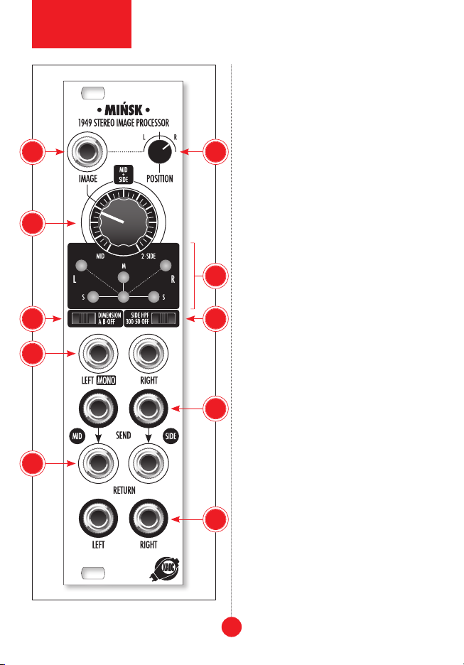
MODule OVerVIeW
The stereo pair of signal inputs 1is AC-cou-
pled and accepts all Eurorack signal levels
The left/right signal pair is translated to
a mid/side pair, and subject to an optional
stereo enhancement process engaged by the
3-position dimension slider switch 2. The
width of the stereo image is controlled by the
image knob 3and external CV patched into
the image jack 4
signal and enabled by the side hpf switch
5. The processed and enhanced pair of mid
and side signals is available at the send pair
of jacks 6. You can apply various external
processing to either of these and patch the
resulting signals to the return jacks 7.
There is an internal normalization from
send to return. If the mid return and/
or side return jacks are left unpatched,
the signal from the send outputs is sent
straight to the return inputs. The mid and
side pair is converted back to normal stereo
and is available at the bottom pair of left
and right jacks 8. The position knob 9
adjusts the left and right output balance.
A set of six LEDs arranged in a setup similar
to the traditional goniometer 10 indicates
the strength of the signal along virtual spa-
tial axes.
MID/SIDe PrOCeSSING
The principle of M/S processing is simple. The
M signal is obtained by a scaled sum of both
left and right signals, while the S signal is a
scaled difference of them. Precision is need-
2
module
explained