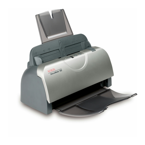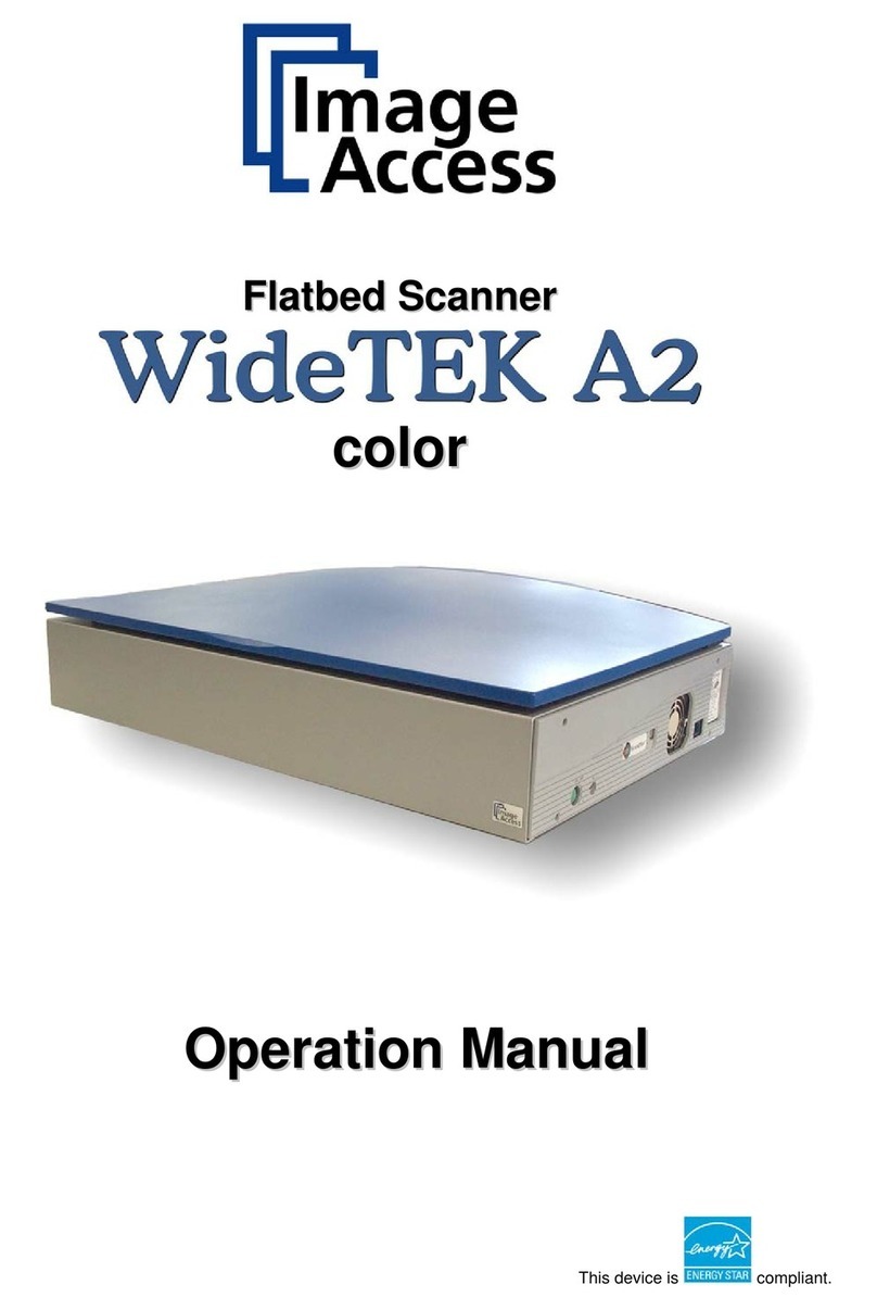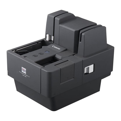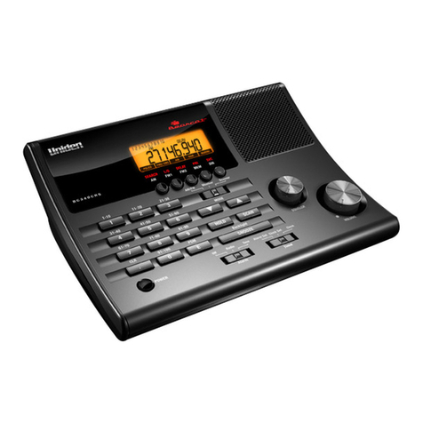
Sheetfed Scanner
Contents
1. INTRODUCTION...........................................................................................................................1-1
1.1 GENERAL NOTES FOR SERVICING..............................................................................................1-1
1.2 GENERAL DESCRIPTION ...........................................................................................................1-2
1.3 BASIC SPECIFICATIONS ...........................................................................................................1-2
2. UNPACKING, INSTALLATION, AND TRANSPORTATION..............................................2-1
2.1 PRECAUTIONS OF INSTALLATION..............................................................................................2-1
2.2 UNPACKING PROCEDURE..........................................................................................................2-1
2.3 INSTALLATION .........................................................................................................................2-3
2.3.1 Installing the ADF Paper Tray............................................................................2-3
2.3.2 Installing the ADF Output Paper Tray ..............................................................2-4
2.3.3 Connecting the Cables.........................................................................................2-5
2.3.4 Turning on the Power ..........................................................................................2-5
2.4 PLACING THE ORIGINAL ...........................................................................................................2-6
3. THEORY OF OPERATION..........................................................................................................3-1
3.1 INTRODUCTION........................................................................................................................3-1
3.2 MAIN CONTROL UNIT................................................................................................................3-2
3.2.1 System diagram....................................................................................................3-2
3.2.2 Main control circuit...............................................................................................3-3
3.2.3 Video circuit: .........................................................................................................3-4
3.2.4 LED and Push Button Module Circuit................................................................3-6
3.2.5 Sensor input ..........................................................................................................3-7
3.2.6 Sub power supply circuit.....................................................................................3-8
3.2.7 Power supply .........................................................................................................3-9
4. PROBLEM SOLVING....................................................................................................................4-1
4.1 DIAGNOSTICS..........................................................................................................................4-1
4.1.1 Online diagnostics ................................................................................................4-1
4.1.2 Offline diagnostics ................................................................................................4-2
4.1.3 Diagnostic flowcharts...........................................................................................4-3
4.2 TROUBLESHOOTING .................................................................................................................4-6
4.2.1 Flowcharts ..............................................................................................................4-6
4.2.2 Tables......................................................................................................................4-9
5. DISASSEMBLY..............................................................................................................................5-1
5.1 SERVICE TOOL.........................................................................................................................5-1
5.2 CLEANING THE ADF ................................................................................................................5-2
5.3 CLEANING THE CALIBRATION AREA..........................................................................................5-3
5.4 PROCEDURE FOR DISASSEMBLY AND REASSEMBLY ....................................................................5-4
5.4.1 Notes on disassembly..........................................................................................5-4
5.4.2 Removing the Upper Housing ............................................................................5-5
5.4.3 Removing the Upper Optical Assembly............................................................5-7
5.4.4 Removing the Upper Optical Chassis ...............................................................5-9
5.4.5 Removing the Lamp in Upper Optical Assembly..........................................5-10
ii

