XICATO XFL User manual

xicato.com
XFL Flexible Linear LED
INSTALLATION INSTRUCTIONS
WET
LOCATION
DC
ONLY
Xicato designs and delivers one of the broadest portfolio spot and linear light sources and
electronics that enable architects, designers and building managers to create beautiful,
smart spaces in which people love to live and work. With thousands of installations around
the globe, Xicato continues to be a leading supplier of high quality lighting solutions.
Xicato is defining the future of intelligent light sources by integrating electronics, software
and connectivity. Founded in 2007, Xicato has offices in China, Europe and the U.S., with
it’s headquarters based in Silicon Valley.

Rev 1.2 | February, 2022 2
WET LOCATION DC ONLY XFL Flexible Linear LED Light Installation Instructions
PRIOR TO INSTALLATION
Water Resistant XFL products are easy to install in straight, curved and irregular spaces with
humid or outdoor conditions. Using high performance solid state lighting technology, light
output, color accuracy and LED brightness, XFL products can create warm and relaxing
environments or bright task lighting.
To maximize the lighting benefits of XFL, a few planning / design steps are recommended
before starting the installation process.
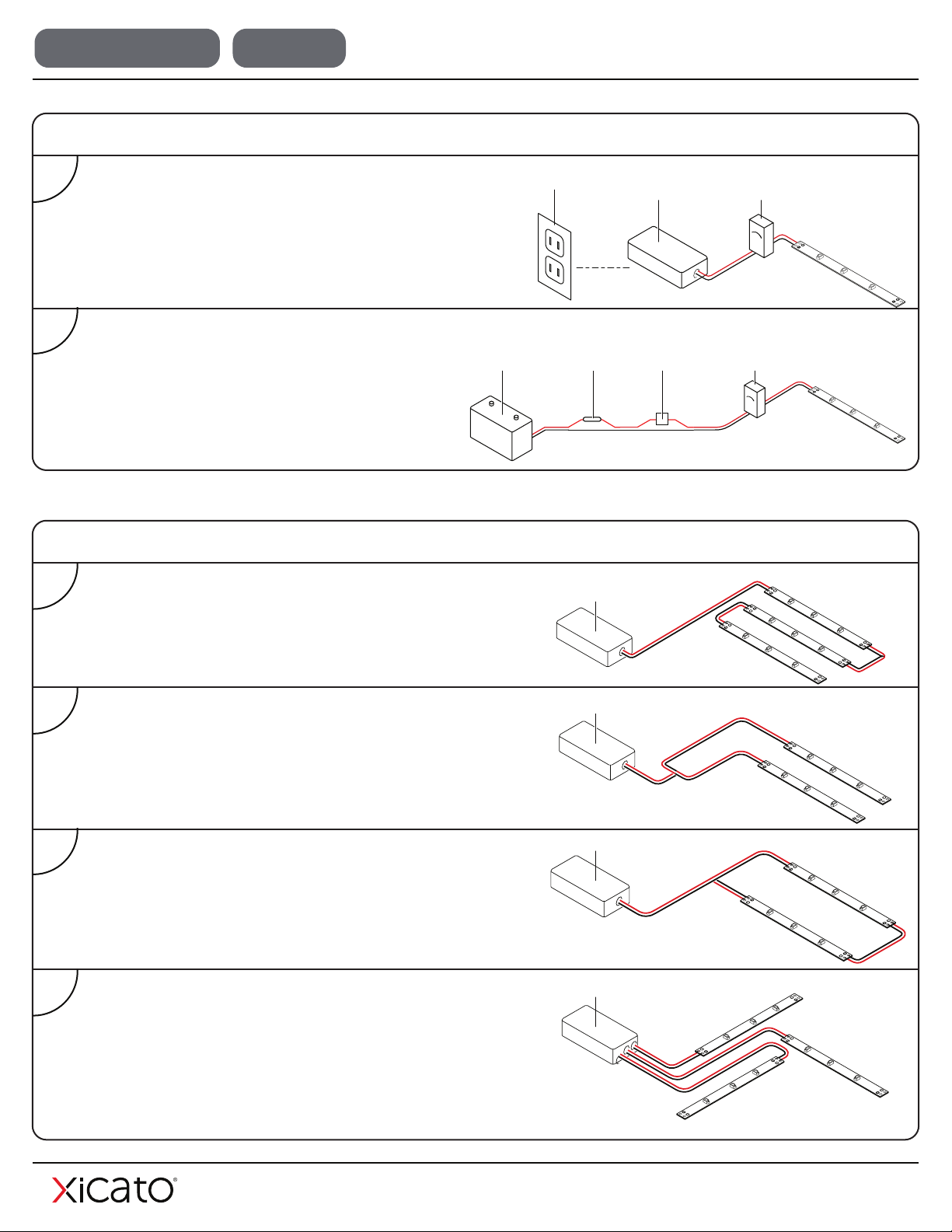
• Where will the power supply be located?
• How will the LED lighting be switched on and off?
• What is the best layout configuration for installation?
• How will wiring be run to the XFL product?
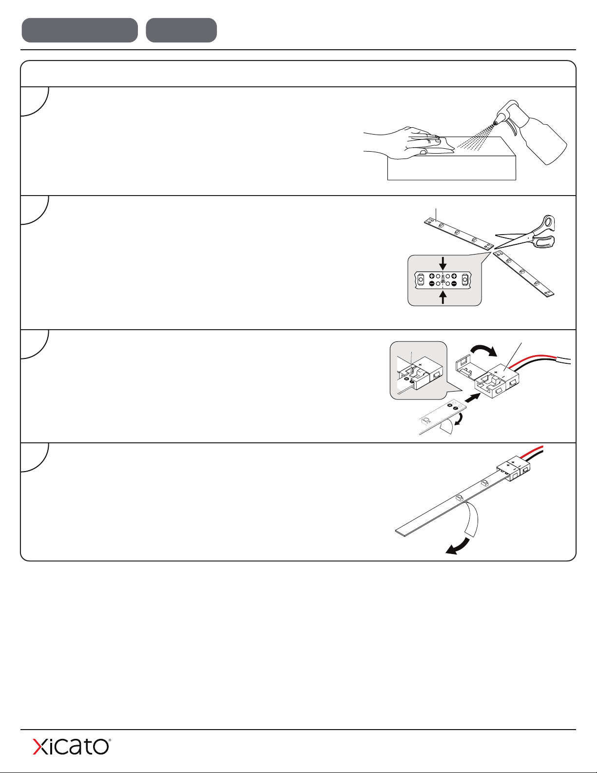
SAFETY AND HANDLING
It is important to read these guidelines completely to understand how the product works,
and how it can be configured, cut to size, connected and installed so you can design your
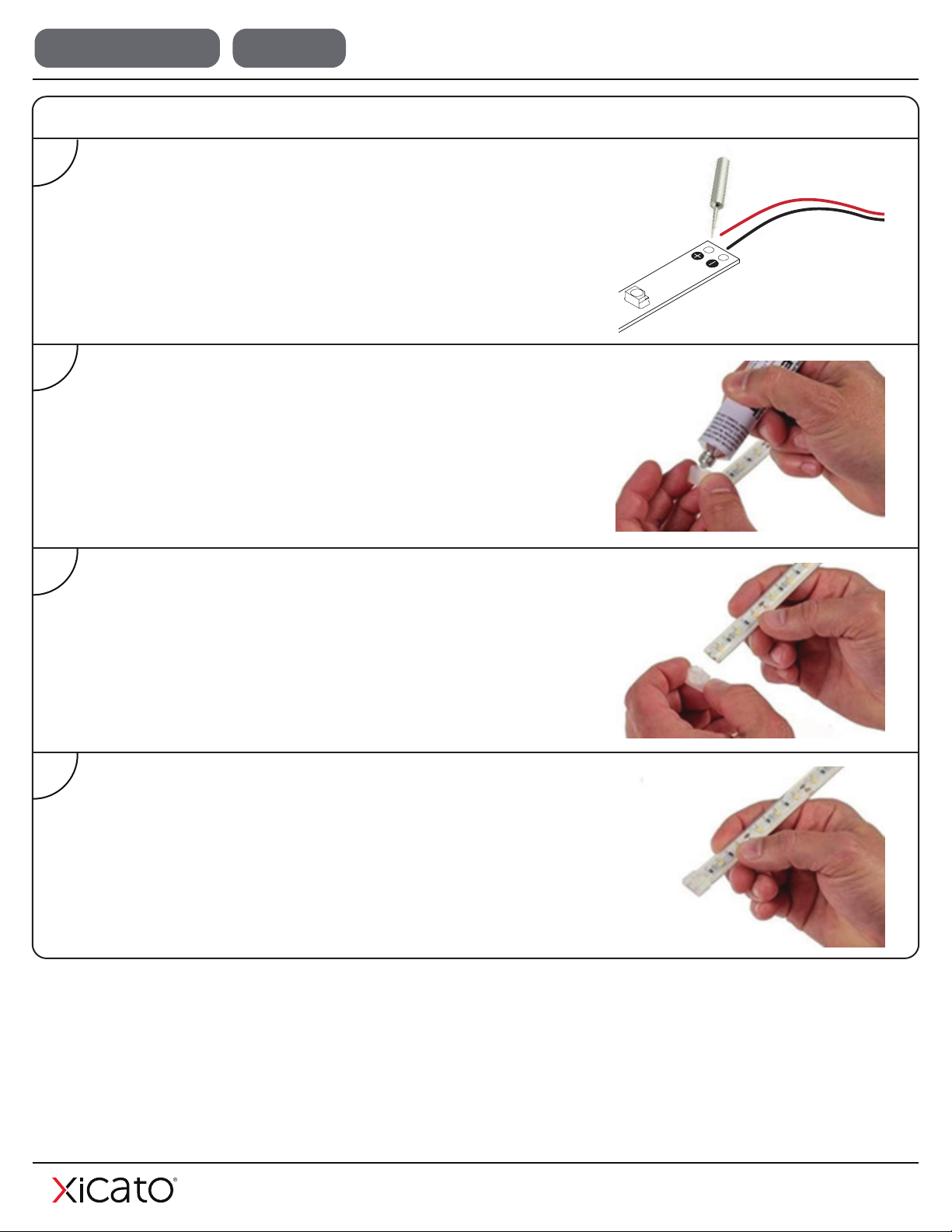
LED lighting layout. Installing flexible linear lighting is easy, however basic wiring skills such
as stripping, splicing, extending, and connecting wires are required.
This product should be installed and serviced in accordance with local and national
electrical code regulations by a qualified, licensed electrician. Failure to follow safety
warnings, and installation instructions will void the warranty for this product.
• Do not stare directly into LED lights when illuminated.
• Do not expose XFL product to direct or indirect moisture.
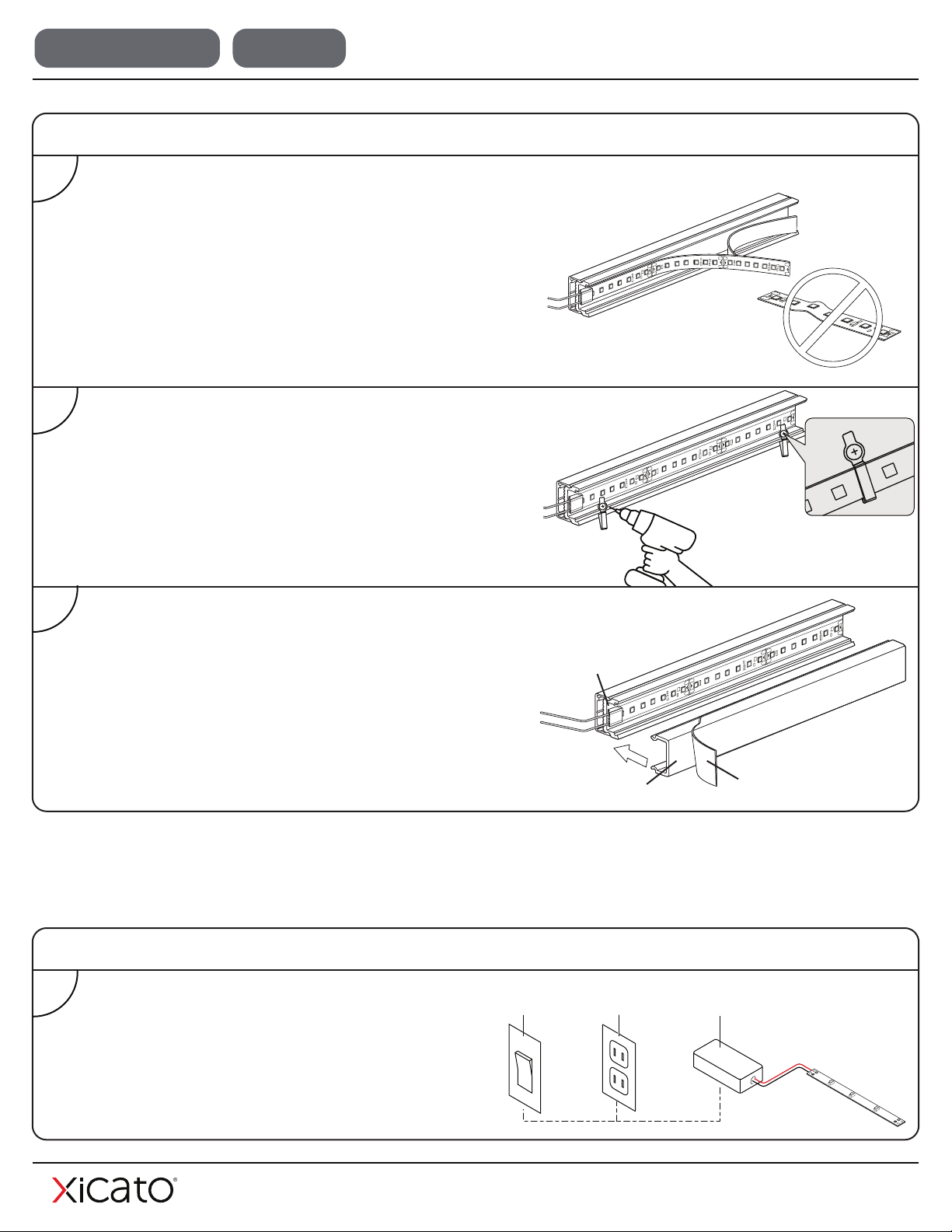
• Do not crimp light strip.
• Do not use sharp objects to handle XFL product
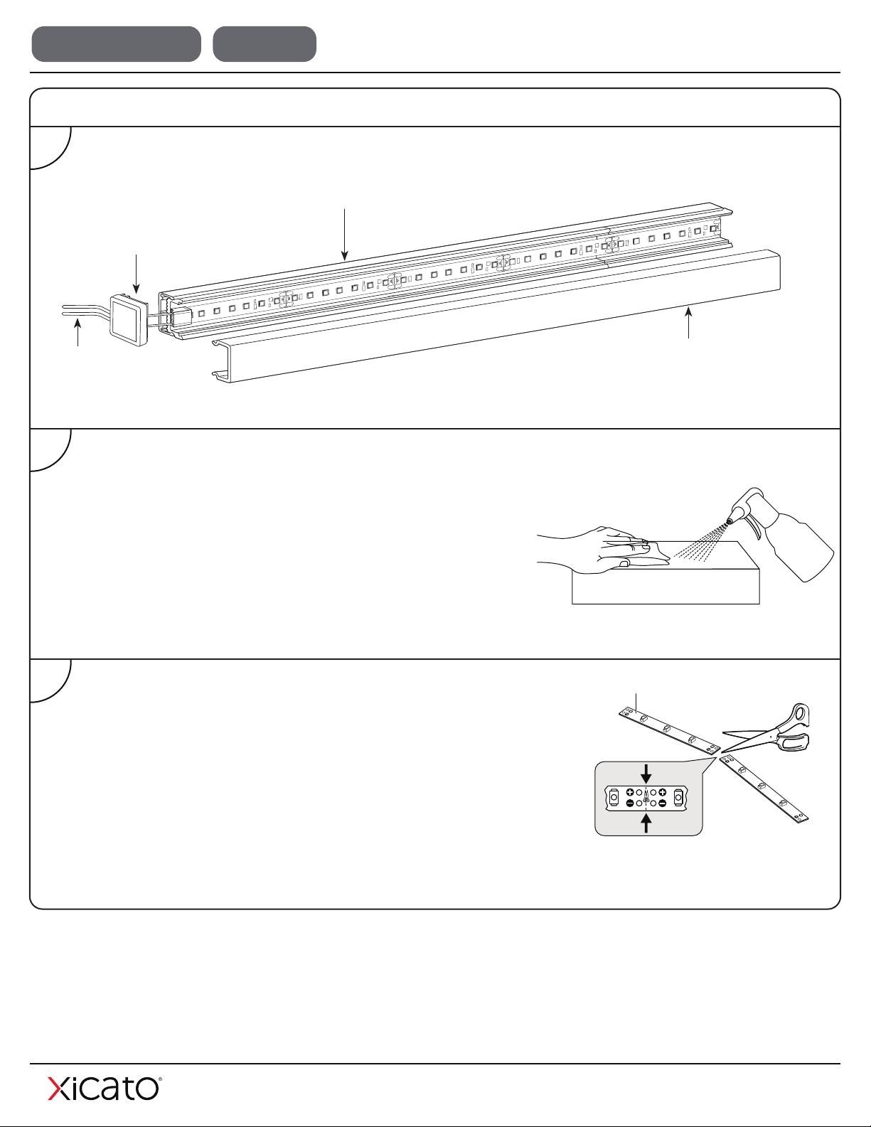
• Only use cutting tools as indicated by these instructions and product markers.
• Unused product should be properly placed and stored in an anti static bag.
• XFL products are designed to provide indirect, accent style lighting.
• XFL products can also be installed inside a channel with diffusing cover for direct and
indirect lighting. Instructions for installation in channel provided.

Rev 1.2 | February, 2022 3
WET LOCATION DC ONLY XFL Flexible Linear LED Light Installation Instructions
Important factors to consider when designing a lighting system are:
• The total lighting wattage the installation will require.
• The length and size of wiring needed to connect light strips to the power supply.
WIRING CONSIDERATIONS
POWER SUPPLY
• XFL product requires a UL Listed Class 2 or SELV 24V DC power supply.
• This product operates on low voltage 24V DC power
• 24V DC power supplies are sold separately in different wattages.
• Polarity symbols should match on input cables.
• Do not connect XFL product to any high voltage AC power supply between 100V - 277V.
• Remove XFL product from reel before applying power.
• Apply power to test XFL product before mounting.
• Do not exceed maximum suggested run length. Doing so may cause inconsistencies in
brightness and performance.
• Do not exceed 80% of power supply rated wattage. Doing so may cause overheating,
shorting, and possible fire. Doing so may also shorten the lifespan of the power supply.
• Always disconnect the power supply before cutting or connecting XFL product.
• Never attempt any work before shutting off the electricity.
BENDING RADIUS
Bending may damage circuit traces.
Do not exceed maximum bend radius specified in XFL data sheet.
ADHESIVE APPLICATION
• The backing tape on XFL products is coated with a
strong adhesive that is intended for a single application only.
• Apply only when a lighting location is fully determined.

Note: Polarity symbols should
match on each component.
Contact Here
Solderless strip-to-wire connector
3
• Peel away a portion of the light strip adhesive backing at one end.
• Open the solderless strip-to-wire connector, and slide the strip
end all the way into the solderless strip-to-wire connector.
• Close the hinged strip-to-wire connector.
4
• Remove the remaining adhesive backing and attach the light strip
to the desired surface.
• Press firmly to ensure proper adhesion.
1
DIRECT INSTALLATION ON SURFACE
• Using a lint-free cloth, wipe the installation surface with 50/50
alcohol solution to ensure a clean mounting surface free of
oils, silicones and dirt particles.
• A smooth mounting surface is required to ensure proper
adhesion.
XFL product
2
• After measuring mounting location, carefully cut the light strip to
desired length.
• Make sure to ONLY cut along the dashed lines provided. These
dashed lines divide two sets of positive and negative connection
points.
Rev 1.2 | February, 2022 4
WET LOCATION DC ONLY XFL Flexible Linear LED Light Installation Instructions

XFL product
• After measuring length of mounting channel, carefully cut the light
strip to desired length.
• Make sure to ONLY cut along the dashed lines provided. These
dashed lines divide two sets of positive and negative connection
points.
3
• Using a lint-free cloth, wipe the installation surface with 50/50
alcohol solution to ensure a clean mounting surface free of
oils, silicones and dirt particles.
• A smooth mounting surface is required to ensure proper
adhesion.
2
1
INSTALLATION IN CHANNELS
Ensure that wires are
long enough to
extend past end cap
Check that end caps and
mounting channels were
included with channel order
Channel and lens sized to ensure that lengths
match. Carefully handle lens to avoid cracking.
Carefully align full length of channel,
with end of one strip to end of next
strip to avoid breaks in lighting.
Rev 1.2 | February, 2022 5
WET LOCATION DC ONLY XFL Flexible Linear LED Light Installation Instructions

INSTALLATION IN CHANNELS (CONTINUED)
6
• Thread wires through or underneath end cap
• Press end-caps firmly into place at either end of channel
5
• Attach the snap-in lens to the channel to protect XFL
product and diffuse lighting.
• Remove protective film from surface of diffuser lens.
Protective lens film
Mounting channel
Lens
4
• Remove adhesive backing starting at one end of XFL product
• Remove backing slowly while adhering XFL product to
mounting channel, making sure not to wrinkle XFL product.
• After removing backing and adhering XFL product to
mounting channel, press firmly to ensure proper adhesion.
Adhesive backing
Do not wrinkle
1
• After measuring mounting location, carefully cut the light strip to
desired length.
• Make sure to ONLY cut along the dashed lines provided. These
dashed lines divide two sets of positive and negative connection
points.
RE-SEALING IP67 XFL
Rev 1.2 | February, 2022 6
WET LOCATION DC ONLY XFL Flexible Linear LED Light Installation Instructions

2
• Solder the lead wires to the tape light, keeping the correct
polarity.
• For these procedures, it is recommended that basic wiring
techniques are followed.
3
• Fill the end cap halfway with a non-acidic neutral silicone sealant,
such as Loctite Superflex SI 5050CL, Dow Corning 737 or
Momentive RTV-11.
• If sealing the wired side of the LED tape, place a small puddle of
sealant where the wires connect to the strip.
4
• Insert the end cap on the end of the strip until the back wall of the
end cap is touching the end of the strip.
5
• Allow 24hrs for the silicone sealant to fully cure.
RE-SEALING IP67 XFL (CONTINUED)
Rev 1.2 | February, 2022 7
WET LOCATION DC ONLY XFL Flexible Linear LED Light Installation Instructions

Rev 1.2 | February, 2022 8
WET LOCATION DC ONLY XFL Flexible Linear LED Light Installation Instructions
• If surface is electrically conductive, isolation between soldering points and mounting surface is necessary.
• Do not install LED tape in a location with direct exposure to the sun or where the operating or storage
temperature is outside the listed temperature range of the product.
• Although XFL products can be installed in curved and irregular spaces, avoid sharp bends or bending on
the solder joints as you could damage the light strip. If an LED is inadvertently damaged and fails to light,
the remaining LEDs will continue to operate.
MOUNTING OPTIONS
Contactt Here
Soldered Contacts
• There are multiple options for connecting XFL. The
procedure at right illustrates how to connect strips using
solderless strip-to-wire connectors.
• Strip-to-wire and strip-to-strip connectors are available for
all XFL products. Compatible connectors must be
selected for specific XFL product type.
• Though solderless connections are generally easier to
use than soldering contacts, in some circumstances,
soldering contacts may be necessary. For procedures
such as soldering and splicing, it is recommended that
basic wiring techniques are followed.
USING SOLDERLESS CONNECTORS
• Another option for quick, easy and flexible connection
between LED light strips is the light strip interconnect,
shown at right.
• Interconnects are a useful option in applications where you
want to easily join light strips over separated surfaces.
USING STRIP INTERCONNECTS

Rev 1.2 | February, 2022 9
WET LOCATION DC ONLY XFL Flexible Linear LED Light Installation Instructions
1
WIRING AND CONNECTION OPTIONS
• Light strip power (off / on) can be controlled using a
wall-mounted switch.
Power supply
24V DC
Wall
switch
Switched
AC outlet
• After attaching mounting clips, attach the snap-in lens
to the channel to protect XFL product and diffuse
the light.
• Remove protective film from surface of diffuser lens.
Protective lens film
Mounting channel
Lens
• Remove adhesive backing starting at one end of XFL product
• Remove backing slowly while adhering XFL product to
mounting channel, making sure not to wrinkle XFL product.
• After removing backing and adhering XFL product to
mounting channel, press firmly to ensure proper adhesion.
Adhesive backing
Do not wrinkle
• Use electric drill and/or screwdriver to install mounting
clips as shown.
• Using mounting clips in addition to the XFL adhesive is
optional, but may be needed depending on the specific
mounting location as well as installer’s judgment.
1
USING MOUNTING CLIPS
2
3

Rev 1.2 | February, 2022 10
WET LOCATION DC ONLY XFL Flexible Linear LED Light Installation Instructions
• Light strips are powered in a continuous “Straight” run.
• Strips that are furthest from the power supply are more likely
to exhibit voltage drop.
Power supply
1
LAYOUT OPTIONS
• Light strips are powered from a spliced “Centerfeed”
connection.
• This type of layout tends to produce more consistent
brightness and color between strips.
Power supply
2
• Light strips are powered from a single looped “Loop-back”
connection, which also produces more consistent results.
• Often used for room perimeter and cove applications.
3
Power supply
• In the “Array” option, light strip “legs” are individually
powered.
• Total wattage should be determined so as not to overload
power supply.
Power supply
4
WIRING AND CONNECTION OPTIONS (CONTINUED)
2
3
• Light strip can be powered directly by a 24V
battery in the absence of an AC outlet.
LED
dimmer
Power supply
24V DC
battery
Fuse
protection
24V DC
switch
• Light strip brightness can be controlled using an LED
dimmer switch.
AC Outlet LED
dimmer
Power supply
24V DC
* Note: Consult your Xicato Sales Rep. for Bluetooth Mesh capabilities.

Extend wire lead up to
10ft. using 22 - 18
AWG wire
• For longer wiring needs between XFL products, another
option is to splice in longer lengths of wiring between two
solderless strip-to-wire connectors, as shown at right.
• Wiring lengths can be increased up to 10 ft (3.05 m), using
22-18 AWG wiring.
LENGTHENING WIRING
Rev 1.2 | February, 2022 11
WET LOCATION DC ONLY XFL Flexible Linear LED Light Installation Instructions
• Voltage drop is the normal loss of voltage that occurs as power flows along a wired connection in low
voltage systems.
• Risk of voltage drop increases as the length of a wired connection is increased.
• Wire length and thickness as well as total light wattage can influence the amount of voltage drop.
VOLTAGE DROP
Recommended Maximum Wire Lengths - Power Supply to Light Strips
22 AWG Wire
Light Strip Length
48 ft (14.63 m)
36 ft (10.97 m)
24 ft (7.32 m)
12 ft (3.66 m)
Max Wire Length
10 ft (3.05 m)
8 ft (2.44 m)
6 ft (1.83 m)
4 ft (1.22 m)
18 AWG Wire
Light Strip Length
48 ft (14.63 m)
36 ft (10.97 m)
24 ft (7.32 m)
12 ft (3.66 m)
Max Wire Length
20 ft (6.10 m)
16 ft (4.88 m)
12 ft (3.66 m)
8 ft (2.44 m)

Rev 1.2 | February, 2022 12
WET LOCATION DC ONLY XFL Flexible Linear LED Light Installation Instructions
TROUBLESHOOTING QUICK GUIDE
Problem Likely Cause Solution
XFL product does not light up.
Incorrect, inadequate or malfunctioning
power supply.
Make sure power supply is turned on and receiving power.
Use a multimeter to test and ensure that XFL product is
receiving 24V DC power.
Incorrect wiring.
Confirm correct polarity (+ to + and - to -) when joining
tape lights as well as when connecting to the 24V DC
power supply. Check at every connection point to ensure
polarity is not reversed.
Only part of XFL product is lit.
OR
XFL product blinks on and off.
Incorrect wiring or insecure connections.
Power supply is inadequate for the
selected length of XFL product.
Check connections on unlit portion of XFL product.
Ensure terminal screws or metal prongs of splice
connectors are pierced through or contacting solder pads.
Install a higher wattage power supply or reduce wattage
by shortening length of XFL product being used.
Overheated power supply. An
overheated power supply will trip the
internal auto-reset of the power supply
repeatedly, turning the system on / off.
Reduce power supply load by shortening the lengths
XFL product being used. Consider relocating power
supply to a cooler location with increased air flow.
Inconsistent brightness along
XFL product
Voltage drop from wires running between
the power supply and XFL product.
Decrease the length of the 24V DC power feed wires or
use thicker gauge wires between the 24V DC power supply
and the XFL product.
Use shorter lengths of XFL product.
XFL product overheats
Ambient temperature is above
recommended rating. Ensure installation environment is rated for XFL product.
Voltage input is higher than
recommended voltage.
XFL product exceeds maximum
recommended run length.
Confirm that power supply output is 24V DC.

Xicato Global Headquarters
102Cooper Court,
LosGatos, CA 95032
Contact Us
Tel: +1 866 223 8395
info@xicato.com
www.xicato.com
For the most up-to-date data sheet, please visit xicato.com/support.
Other manuals for XFL
2
Table of contents
Other XICATO Lighting Equipment manuals
Popular Lighting Equipment manuals by other brands

Chauvet
Chauvet 4 Bar Flex user manual

Federal Signal Corporation
Federal Signal Corporation SLR LED Installation and maintenance manual

LED Group
LED Group ROBUS R8MU instructions

Wagan
Wagan Classic Lantern user manual

EuroLite
EuroLite IP AUDIENCE BLINDER user manual

thomann
thomann STAIRVILLE Led Par 64 CX-7 CW/WW/A user manual