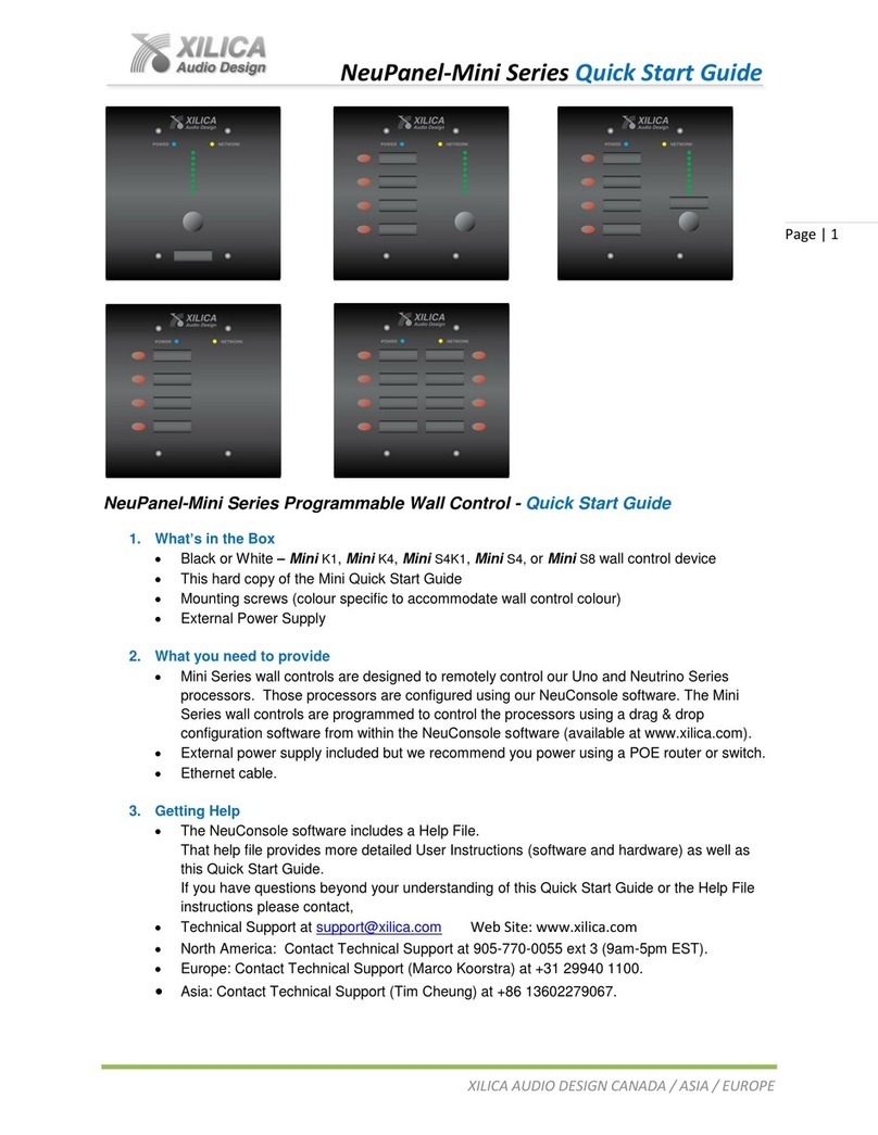
Xilica Audio Design NEUPANEL MINI User manual

NEUPANEL MINI
Product Installation Guide

Important Safety Information
1. READ THESE INSTRUCTIONS
All the safety and operating instructions should be read before the product is operated.
2. KEEP THESE INSTRUCTIONS
The safety and operating instructions should be retained for future reference.
3. HEED ALL WARNINGS
All warnings on the product and in the operating instructions should be adhered to.
4. FOLLOW ALL INSTRUCTIONS
All operating and use of instructions should be followed.
5. DO NOT USE THIS APPARATUS NEAR WATER
Do not use the product near water. For example, near a bathtub, washbowl, kitchen sink, or laundry tub, in a wet basement, or near a swimming pool, and
the like.
6. CLEAN ONLY WITH DRY CLOTH
Unplug the unit from the wall outlet before cleaning
7. DO NOT BLOCK ANY VENTILATION OPENINGS
Slots and openings in the cabinet back or bottom are provided for ventilation, to ensure reliable operation of the limit and to protect it from overheating.
These openings must not be blocked or covered. The openings should never be blocked by placing the product on a bed, sofa, rug, or similar surface.
This product should never be placed near or over a radiator or heat source. This product should not be placed in a built-in installation such as a bookcase
or rack unless proper ventilation is provided or the manufacturer’s instructions have been adhered to.
8. DO NOT INSTALL NEAR ANY HEAT SOURCES
This Product should be situated away from heat sources such as radiators, stoves, or other products (including ampliers) that produces heat.
9. DO NOT DEFEAT THE SAFETY PURPOSE OF THE POLARIZED OR GROUNDING-TYPE PLUG
A Polarized plug has two blades with one wider than the other. A grounding-type plug has two blades and a third grounding prong. The wide blade or the
third prongs are provided for your safety. If the provided plug does not t into your outlet, consult an electrician for replacement of the obsolete outlet.
10. PROTECT THE POWER CORD FROM BEING WALKED ON OR PINCHED PARTICULARLY AT PLUGS, CONVENIENCE RECEPTACLES, AND
THE POINT WHERE THEY EXIT FROM THE APPARATUS.
11. ONLY USE ATTACHMENTS/ACCESSORIES SPECIFIED BY THE MANUFACTURER.
12. USE ONLY WITH CART, STAND, TRIPOD, BRACKET, OR TABLE SPECIFIED BY THE MANUFACTURER, OR SOLD WITH THE APPARATUS.
WHEN A CART IS USED, USE CAUTION WHEN MOVING THE CART/APPARATUS TO AVOID INJURY FROM TIP-OVER.
Do not place this unit on an unstable cart, stand, tripod, bracket, or table. The unit may fall, causing serious injury to someone, and serious damage to
the appliance. A unit and cart combination should be moved with care. Quick stops, excessive force, and uneven surfaces may cause the product and cart
combination to overturn.
13. UNPLUG THIS APPARATUS DURING LIGHTNING STORMS OR WHEN UNUSED FOR LONG PERIODS OF TIME.
For added protection for this unit during a lightning storm, or when it is left unattended and unused for long periods of time, unplug it from the wall outlet
and disconnect the antenna or cable system. This will prevent damage to the unit due to lightning and power line surges.
14. REFER ALL SERVICING TO QUALIFIED SERVICE PERSONNEL. SERVICING IS REQUIRED WHEN THE APPARATUS HAS BEEN DAMAGED IN
ANYWAY, SUCH AS WHEN THE POWER SUPPLY CORD OR PLUG IS DAMAGED, LIQUID HAS BEEN SPILLED OR OBJECTS HAVE FALLEN INTO
THE APPARATUS, THE APPARATUS HAS BEEN EXPOSED TO RAIN OR MOISTURE, DOES NOT OPERATE NORMALLY, OR HAS BEEN DROPPED.
15. WARNING: TO REDUCE THE RISK OF FIRE OR ELECTRIC SHOCK, DO NOT EXPOSE THIS APPARATUS TO RAIN OR MOISTURE.
16. APPARATUS SHALL NOT BE EXPOSED TO DRIPPING OR SPLASHING AND NO OBJECTS FILLED WITH LIQUIDS, SUCH AS VASES, SHALL BE
PLACED ON THE APPARATUS.

Surface Mount
Included with each Mini control is a surface mount back box that the Mini comes mounted into
inside the product carton. This back box is designed to be mounted externally on a wall or surface.
The surface back box has an angled mounting surface that allows the Mini control to be rotated to
meet the desired view angle and is secured to the back box with 4 x M8 metric screws.
Note: It is always recommended before installing the device to disconnect the power to prevent
the power from shorting to the chassis.
Flush Wall Mount
Mini controls can be flush in-wall mounted in new or existing construction applications. It is very important to read this guide in its
entirety before starting your installation.
Note: Each Mini model comes in its carton inserted into a surface mount angled back box. Remove the Mini from our back box. The 4
screws are M8 metric thread. These screws cannot be used in electrical boxes in N. America. Use the 4 x #6-32 SAE screws that come
in a bag with each Mini for installations in N. America.
It is extremely important that the Mini control is NOT powered on during the installation or removal process. The circuit board can
short out against the metallic box, damaging the hardware, and possibly the PoE switch.
For New Work Construction, a 4" x 4" electrical back box with a minimum depth of 2" and a mud ring (if used) with a depth of
1
⁄
2
" for
proper clearance are required.
Note: If mud rings are used - they may vary slightly depending on the manufacturer and depth of the ring itself. It may be necessary
to modify the corners of the mud ring for proper fit. The corners on the mud ring as shown below right have a larger radius than the
one on the left and will need a bit of filing for the Mini wall controller to fit. (The Appleton
1
⁄
2
" mud ring shown at the left below will fit
without modification)
Under very special situations the wall controller may have to be installed “Live” or in a
powered on state. This is NOT recommended, however, it is possible to insulate the left
portion of the mud ring with a large piece of electrical tape. This will insulate it from the
circuit board while sliding the wall controller through the opening of the mud ring.
Small Radius
Fits Perfectly
Larger Radius Will
Need Modification
Electrical Tape Provides Insulation
Circuit Board Requires Protection

For Existing/Old Work Construction applications, we recommend using either an old work cut in/clamp in style full back box like the
Thomas & Betts BH234 shown below left or an old work cut-in/clamp In style mounting ring/bracket like the Cooper Industries B-Line
cut-in ring part # BB20L shown below right - or other brands - which will fit nicely as it lies thin and flat against the wall. Again, use the
4 x
6
⁄
32
SAE screws that come in a bag with each Mini for this N. America brand of mounting ring. Use the included M8 metric screws
for cut-In rings from Europe or Asia.
Note: If the wall is insulated it is important that the wall insulation is moved away from the wall controller for proper convection
cooling.
Rack Mount
Many installations require the system controllers to be mounted in an equipment rack. Xilica offers our optional Mini-RMKIT - a 19",
3RU rack mount panel with pre-cut 2-gang threaded cutouts that you can flush mount up to three (3) Mini controls into.
As shown at the right.
When rack mounting Mini control units, they can be powered locally using
the included external power supply. Note: The 5VDC power supply can be
daisy chained to more than one Mini control in the rack. A PoE switch or
Injector can also be used in lieu of the external power supply.
Use the 4 x M8 metric thread screws that are used to mount the Mini control
into its supplied surface mount box included in the product carton when
mounting the Mini controls into our Mini-RMKIT rack mount panel (or back
boxes and adapters manufactured In Europe and Asia).
Use the
6
⁄
32
SAE screws that come in the bag with each Mini control to mount the
Mini controls into any rack mount panel, back box, or adapters manufactured in
N. America.
Labeling Mini Controls
Each Mini control model includes a method to label the assigned functions giving users a general
understanding of the controller's function as well as a clean professional look. For each function a
recessed label slot area with a clear plastic cover has been incorporated providing a flush look. The
clear plastic cover snaps into place after the label has been installed.
The maximum label size is .95" W (24mm) x .275" H (6.8mm). A professional labeling device or a
standard office-labeling machine such as a Brother P-Touch with 6mm width tape can be used to
create your Mini control labels.
Or, an Excel template is available that was designed to allow the integrator to create labels.
This template can be found on the Xilica web site at www.xilica.com.

Mini Control - Wall Mounting Requirements
Surface Mount
1. Surface mount back box/can and Mini mounting screws - 4 x M8 metric thread - are included in the product carton
2. CAT5e or CAT6 cable with a RJ45 connector
3. Power - PoE switch or PoE injector (not included) or 5VDC external power supply (included)
4. Screws to mount Mini surface mount back box to the wall or surface (not included)
Flush Mount
New Construction
1. Electrical back box/can, 2 gang, 2" deep (not included)
2. Mud ring (if utilized), 2 gang
1
⁄
2
" or
3
⁄
4
" depending on installation (not included)
Note: The internal corners of different cut-in ring/box brands can vary and interference may be an issue. It is important to know
some minor corner modifications may be required.
3.
6
⁄
32
x .75" Qty 4 screws (included in a bag with each Mini) to mount the Mini control into N. America new construction electrical
boxes. Or use the supplied metric M8 screws that are used to mount the Mini control into the supplied surface box included in
the product carton for new construction electrical boxes In Europe and Asia.
4. CAT5e or CAT6 cable with a RJ45 connector
5. Power - PoE switch or PoE injector (not Included) or 5VDC external power supply (included)
Existing Construction
1. 2 gang cut in ring (not included)
The Cooper Industries B-Line brand of cut-in ring part # BB20L (N. America) will fit nicely as it lies thin and flat against the wall
Note: The internal corners of different cut-in ring/box brands can vary and interference may be an issue. It is important to know
some minor corner modifications may be required.
2.
6
⁄
32
x .75 Qty 4 screws (included in a bag with each Mini) to mount the Mini control into N. American cut in rings. Or use the
supplied M8 metric screws that are used to mount the Mini control into the supplied surface box included in the product carton
for existing construction cut-in rings in Europe and Asia.
3. CAT5e or CAT6 cable with a RJ45 connector
4. Power - PoE switch or PoE injector (not Included) or 5VDC external power supply (included)
Rack Mount
Rack Mount 19" Width Racks - 3RU Panel - Pre-Cut 2-Gang Threaded Cutouts (Up to 3 Mini Controls Per Panel)
1. Optional Mini-RMKIT rack mount panel
2. CAT5e or CAT6 cable with a RJ45 connector
3. Power - PoE switch or PoE injector (not included) or 5VDC external power supply (included)
4. Included 4 x M8 metric thread screws to mount the Mini control into the Mini-RMKIT rack mount panel. Or use the
6
⁄
32
x .75"
Qty 4 screws (included in a bag with each Mini) to mount the Mini control into rack mount panels manufactured in N. America.

Customer Support
If you’d like to contact us regarding product support
we’ll connect you with a solutions engineer. Alterna-
tively, if you’d like to speak to someone, you can call
the following numbers for immediate assistance:
North America & Rest of World: +1 905-770-0055
Europe: +31 29940-1100
China & Hong Kong SAR: +852 2604-9382
www.xilica.com
Version: 1.0
Table of contents
Other Xilica Audio Design Controllers manuals