List of figures and tables
9
List of figures and tables
Figure 1 XtremeDSP Spartan-3A DSP Development Board block diagram ..............................................................11
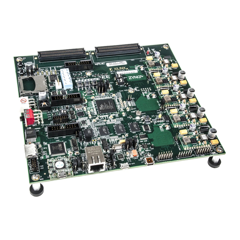
Figure 2 XtremeDSP Spartan-3A DSP Development Board top view ....................................................................... 12
Figure 3 XtremeDSP Spartan-3A DSP Development Board power supply diagram ................................................. 19
Figure 4 XtremeDSP Spartan-3A DSP Development Board bottom view................................................................. 26
Figure 5 XtremeDSP Spartan-3A DSP Development Board JTAG chain.................................................................. 31
Figure 6 IDT Programmable Clock ............................................................................................................................ 37
Figure 7 Detailed I/O configuration of the 5V9885.................................................................................................... 38
Figure 8 Assigning the register settings...................................................................................................................... 39
Figure 9 Programming the XtremeDSP Spartan-3A DSP Development Board with iMPACT ................................. 40
Table 1 FPGA USB/System ACE interface pinout..................................................................................................... 13
Table 2 Ethernet PHY default configuration .............................................................................................................. 14
Table 3 Soft Touch connector pin assignments .......................................................................................................... 15
Table 4 FMC expansion connector pin assignments (1)............................................................................................. 16
Table 5 FMC expansion connector pin assignments (2)............................................................................................. 17
Table 6 Mictor pin assignments.................................................................................................................................. 18
Table 7 FPGA I/O bank voltage rail........................................................................................................................... 20
Table 8 Clock generator default settings..................................................................................................................... 20
Table 9 I2C FPGA pin assignments ............................................................................................................................ 20
Table 10 User-defined button FPGA pin assignments................................................................................................ 21
Table 11 Serial port FPGA pin assignments............................................................................................................... 22
Table 12 Reset connection.......................................................................................................................................... 22
Table 13 Configuration jumpers ................................................................................................................................. 22
Table 14 User-defined DIP switch FPGA pin assignments ........................................................................................ 23
Table 15 User-defined LED FPGA pin assignments .................................................................................................. 23
Table 16 Configuration DIP switch functions ............................................................................................................ 23
Table 17 Configuration modes ................................................................................................................................... 24
Table 18 Status LED signals....................................................................................................................................... 24
Table 19 Audio connectors ......................................................................................................................................... 25
Table 20 FPGA DDR2 interface pinout...................................................................................................................... 27
Table 21 I2C slave device addresses ........................................................................................................................... 30
Table 22 FMC standard rule and recommendation violations .................................................................................... 35
Table 23 Register configuration.................................................................................................................................. 39
