Xlink ITC-BTTN User manual

1
ITC-BTTN Cellular Bluetooth Gateway
Owner’s Manual

2
Introduction .......................................................................................................................................3
Package Contents.............................................................................................................................3
XLink Connections Diagram.........................................................................................................4
Setup.....................................................................................................................................................5
Pairing your Bluetooth Cell Phone to the XLink..............................................................6
Automatic Bluetooth Connection........................................................................................7
Manual Bluetooth Connection..............................................................................................8
Testing the Setup .............................................................................................................................8
Light Indicators .................................................................................................................................9
Using the XLink .................................................................................................................................10
Placing a Call...............................................................................................................................10
Selecting a Line..........................................................................................................................11
Receiving a Call..........................................................................................................................11
Force Call Connection .............................................................................................................12
Speed Dialing .............................................................................................................................12
Voice Mail.....................................................................................................................................13
Caller ID.........................................................................................................................................14
Call Waiting..................................................................................................................................14
Voice Dialing...............................................................................................................................14
Computer Connectivity..................................................................................................................15
Troubleshooting ...............................................................................................................................15
Warranty ..............................................................................................................................................18
Safety and Regulations...................................................................................................................19
FCC Notices .................................................................................................................................21
Calling 911...................................................................................................................................21
Wall Mount Information.................................................................................................................22
TABLE OF CONTENTS

3
INTRODUCTION
Congratulations on your purchase of the XLink ITC-BTTN Cellular Bluetooth Gateway.
In addition to your regular telephone line you will now be able to access up to 3
Bluetooth enabled cell phones from any standard telephone connected to the XLink.
XLink ITC-BTTN is designed to work with or without telephone service (land line).
WARNING:
• If the RED Error light starts ashing then the lines connected to the XLink
have not been connected properly. In this case immediately check that
connections from the telephone to the XLink and/or from the telephone
service line are correctly installed. When connections are correct the red light
does not ash and the green light remains on.
PACKAGE CONTENTS
Each XLink ITC-BT gift box includes the following.
• XLink ITC-BT Unit
• 9-Volt DC Power Adapter
• Vertical Stand
• Quick Start Guide
• Owner’s Manual
• Telephone Cord

4
XLINK CONNECTIONS DIAGRAM
CELL PHONE #3 Button & Status Light
CELL PHONE #2 Button & Status Light
CELL PHONE #1 Button & Status Light
TELEPHONE CORD CONNECTION
ERROR LIGHT
POWER ADAPTER CONNECTION
USB CONNECTION
POWER INDICATOR
TELEPHONE SERVICE LINE CONNECTION

5
SETUP
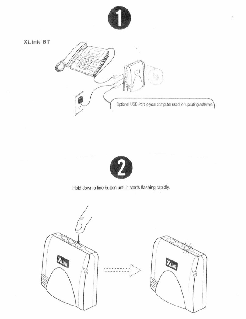
1. Connect stand to your XLink as included in your
gift box.
2. Plug a standard corded or cordless telephone
into the XLink using a regular telephone cord.
3. Plug the telephone service line into the XLink
using the cord from the wall.
4. Plug the supplied power adapter into the XLink
and the other end into a wall power outlet.
5. To pair your Bluetooth cell phone refer to “Pair
your Bluetooth cell phone to the XLink.”
HINTS:
• Place your cell phone where you have the best reception in your home or
oce.
• For best audio quality keep your cell phone within 10 feet of the XLink unit.
• Using a multi handset cordless phone gives you multiple extensions.
• Certain cordless phones that operate in the 2.4 GHz frequency range may
interfere with the cell phone reception. Keep as much distance as possible
between the XLink and these types of cordless phones.
• Some wireless networks, such as 802.11 and Wi-Fi, may interfere with
Bluetooth radio signals. Keep as much distance as possible between this type of
equipment, the XLink and your cell phones.
HOME PHONE
WALL OUTLET
STAND
TO WALL

6
Each XLink ITC-BTTN can be paired to three dierent cell
phones, one for each line. To pair a Bluetooth cell phone to
a line perform the following steps:
1. Press and hold one of the three line buttons on the
XLink ITC-BTTN until it ashes rapidly (keep button
pressed for approximately 4 seconds).
2. Put your cell phone into the mode where it searches for
Bluetooth devices (similar to searching for a Bluetooth car kit). This may be found in
your cell phone’s menu under ‘Tools’, ‘Setup’, ‘Bluetooth’ and/or ‘ Connections’ menu.
If given the choice, search for ‘Handsfree’ devices and select “Look for Devices”. Your
cell phone should then scan/search for Bluetooth devices
3. When the XLink is found XLink will be displayed on your cell phone’s LCD. Accept this
device. In order to accept, your cell phone may ask you to do so by pressing any number
of selections including; ‘select’, ‘bond’, ‘pair’, ‘yes’, ‘ok’, etc.
4. Enter the pass code: 1 2 3 4
5. Once the pairing is complete, the selected line’s blue light button on the XLink will
stop ashing quickly and remain solid.
Once paired, the XLink will remember the cell phone. Automatic connecting occurs
whenever the cell phone is within range (approx. 30ft.) of your XLink.
PAIRING YOUR BLUETOOTH ENABLED CELL PHONE
TO THE XLINK

7
HINT:
•Each line can only be paired to ONE cell phone at a time.
• A line can be paired to a dierent cell phone at any time by repeating the
pairing procedure.
•(as soon as pairing is started for a line) Previous pairing
information is lost.
• A paired line can be “unpaired” and prepared for re-pairing by holding
down the line button until the button ashes rapidly.
• The pairing process can be aborted at any time by pressing the line button.
The previous paired cell phone will be disconnected.
Once a line is paired to a cell phone it will automatically try to connect. When the cell
phone goes out of range, the line light will ash slowly to indicate it is not connected and
is searching for the cell phone. When the cell phone comes into range of the XLink it will
automatically connect to the XLink and the line light will turn solid blue to indicate the
connection.
If you are on a call and walk into range, the XLink ITC-BTTN and cell phone will
automatically connect. You will be able to continue your call without interruption.
If a line light is not ashing and you wish to place the line into automatic connection mode,
simply press the line button once.
AUTOMATIC BLUETOOTH CONNECTION

8
You may not want live calls to be transferred automatically or you may want to force the
cell phone to disconnect from the XLink.
When a line is connected (blue light remains on) pressing the line button will disconnect
that line and the light will turn o once disconnected. Audio will be transferred to the cell
phone and you can continue your call on the cell phone.
When a line is not connected and not searching (blue light remains o) pressing the line
button will put the line into searching mode (blue light ashes slowly). If the cell phone
has been previously paired and is within range the cell phone will connect with the XLink
and the blue light will remain solid.
NOTE:
• Some cell phones will prompt you when you come within range of the XLink. You can
then decide if you want to transfer the call to the XLink.
After connecting one or more telephones to the XLink, the setup test feature can be
used to ensure proper connections.
1. Ensure the green light is on and the red light is not ashing.
2. Simultaneously press and hold the line 1 and line 2 buttons for approximately two
seconds: all telephones connected to the XLink should start ringing.
HINT:
• If an extension telephone does not ring, check that it is powered and that all
cables are properly connected.
MANUAL BLUETOOTH CONNECTION
TESTING THE SETUP

9
NOTE:
• Some older analog telephones may not ring properly when connected to the
XLink ITC-BTTN. Avoid these types of phones.
GREEN Solid
Indicates the unit is powered up and running
normally.
GREEN Flashing
Indicates there is an incoming call on the
telephone service line (land line)
RED Flashing
Indicates the XLink connections have not been
connected properly. Immediately re-check line
connections until the RED light turns o and the
green light remains on.
BLUE Solid
Indicates the selected line is connected to cell phone
BLUE Fast Flash
Indicates the selected line is in pairing mode. Use your cell phone to search and pair to
the XLink.
BLUE Uneven Flash
Indicates the selected line is connected to cell phone and there is an incoming call on
this line.
LIGHT INDICATORS BLUE

10
To use the XLink connect your normal corded or cordless telephone into the connector
on the XLink with a standard telephone cable. This phone is now your extension
telephone. To use your telephone service line, connect the telephone service line to
the designated connection on the XLink (see page 4 for Connection Diagram).
BLUE Slow Flash
Indicates the selected line is paired but the cell phone is currently out of range and/or
temporarily not connected. XLink is actively searching for this cell phone.
BLUE O
Indicates the selected line is not paired or not searching for a cell phone (Manual
Connection Mode).
USING THE XLINK
PLACING A CALL
XLink ITC-BTTN is designed to work with your standard phone and your telephone service
or independently of your telephone service. If you have connected your telephone service
line to the XLink you will dial out directly by simply picking up the phone and dialing. If you
wish to dial out on your cell phone simply select the appropriate line, “one” “two” or “three” by
pressing 1 FLASH , 2 FLASH , or 3 FLASH accordingly and dial the desired number.
To place a call on any telephone connected to the XLink, simply pick up the handset
and dial the number. When dialing out using a cellphone connected to the XLink, an optional
# digit may be dialed at the end of the number to activate dialing immediately, the same as

11
SELECTING LINE
If connected to the telephone service line (land line) the XLink will dial out from
the regular phone using the land line. You can choose to dial out using a cell
phone by selecting the appropriate line that is paired to the cell phone you wish
to dial out on.
A specific line can be specified on a per call basis by first dialing the desired line
number and then pressing the FLASH key on your telephone.
Example: To specify line 3 for an outgoing call, dial 3 FLASH , then dial the
intended phone number.
If the XLink is not connected to the telephone service line (land line), the XLink
uses the lowest line number with a connected (paired) cell phone for outgoing
calls. For example, if cell phones for lines 2 and 3 are connected, all outgoing
calls will be made on line 2.
Anytime a rapid series of beeps is heard instead of normal dial tone, that
specific line (or any line) is not available for outgoing calls. This is because the
XLink has not been paired with a cell phone or the cell phone is out of range.
the Send button on the cell phone. Dialing a # is not required. The dialing process will start
following a short delay after the last digit is dialed.
After picking up a telephone connected to the XLink, you should hear a steady dial
tone, if you hear an error tone (series of rapid beeps), there are no lines available for an
outgoing call. In this case, check to ensure that you have at least one cell phone paired
and connected to the XLink. Also check that the telephone service line is connected
properly to the XLink.

12
Sometimes dial tone will be heard when an extension telephone is picked up to
continue an active call that was transferred from your cell phone to the XLink.
When this happens dialing *# can be used to connect the call.
FORCE CALL CONNECTION
SPEED DIALING
When a cell phone that has been paired and is currently connected with the
XLink rings, all telephones plugged into the XLink will also ring.
Each line has its own distinctive ring pattern, allowing you to immediately know
which cell phone the current call is coming in on.
You can also tell which line is ringing by looking at the line buttons on top of the
XLink. The blue light for a ringing line will flash with a unique cadence.
Some cell phones support speed dialing. The XLink allows you to access speed
dials 2 through 9 from extension telephones. Use the following steps:
1. Pick up an extension telephone. Listen for dial tone.
2. OPTIONAL: Select Line: 1 FLASH or 2 FLASH or 3 FLASH
3. Dial speed dial digit, 2 to 9
4. Dial #
Example: To activate speed dial 3 on a the cell phone paired to line one, press
1 FLASH followed by 3 #
RECEIVING A CALL

13
NOTE:
• This feature may not be supported by all cell phones.
• The speed dial numbers for each line are determined by the individual cell
phones.
VOICE MAIL
You can access your cell phone voice mail from extension telephone. Before
this feature will work you may have to program your voice mail number into the
XLink.
1. Pick up an extension telephone. Listen for dial tone.
2. OPTIONAL: Select Line: 1 FLASH or 2 FLASH or 3 FLASH
3. Dial 1 #
If attempting to listen to your voice mail results in an error tone or in the wrong
number being dialed, a different voice mail number can be programmed for each
line. Use the following steps to program the voice mail number:
1. Pick up an extension telephone. Listen for dial tone.
2. Dial * * 0 0 0
3. Press the key indicating the line number you want to program: Either line 1 2
or 3
4. Dial the desired voice mail number.
5. Press the FLASH key.
6. Hang up the extension set.

14
If your cell phone supports voice dialing then the XLink may be able to access this
feature. The following steps may allow you to voice dial from extension telephones:
1. Pick up an extension telephone. Listen for dial tone.
2. OPTIONAL: Select Line: 1 FLASH or 2 FLASH or 3 FLASH
Caller ID will display the incoming call information on the LCD of your extension sets.
For this feature to work, both the cell phone and your extension telephones must
support caller ID.
NOTE:
• This feature may not be supported by all cell phones.
• Most cell phones only provide the caller number and not the name.
The XLink will generate a call waiting tone to alert you to another incoming call on any
of the 3 lines. When you hear a call waiting tone, press the FLASH (or CALL WAITING or
LINK , etc.) button on the extension telephone. This will connect the second caller.
Pressing the FLASH key will then toggle through all active calls.
NOTE:
• This feature may not be supported by all cell phones.
CALLER ID
CALL WAITING
VOICE DIALING

15
NOTE:
• Not all cell phones support this feature and not all cell phones enable the
XLink to access this feature.
The XLink has a USB port that allows the XLink to communicate with a computer
running the proper software (not supplied). Please see the XLink website (www.
xlinkgateway.com) to upgrade rmware and congure your XLink.
TROUBLESHOOTING
Red light is ashing
Indicates the line connections made to the XLink have not been done properly. Re-check
line connections (see page 4 Connections Diagram). Connections are correct when the
red light is not ashing and the green light remains on.
Cell phone does not pair to XLink
Hold down one of the line buttons until the blue light ashes rapidly. The line is now
ready to be paired (see section “Pairing your Bluetooth Cell phone to the XLink”).
COMPUTER CONNECTIVITY
3. Dial # #
4. Say name or follow voice prompts from cell phone.

16
Cell phone is paired but will not connect
The line that the cell phone is paired to is not in Auto Connect mode (see section
Automatic Bluetooth Connection). Press and release the line button so that the blue
light ashes slowly. The line is now searching for the cell phone.
No dial tone on extension telephone
Check that the RED light on the XLink is not ashing. Ensure your extension
telephone(s) are properly plugged into the XLink. If the GREEN light is not on, check
the power cord is connected properly. See section “Testing the Setup”.
Error/busy tone on extension(s)
No cell phones are currently connected. Ensure a cell phone that has been paired (see
section Pairing your Bluetooth Cell Phone to the XLink) with the XLink ITC-BT is within
range. Ensure the line is in Auto Connect mode (see section Automatic Bluetooth
Connection).
No caller ID shown on extension telephone
Your cell phone and cellular service plan must have caller ID enabled. Not all cell
phones support passing the caller ID information to accessories such as the XLink,
even though they may show this feature on the cell phone screen.
Caller ID does not show name
Generally, the name must be stored in the cell phone book for this to work. Many cell
phones do not support passing the caller name information to accessories such as the
XLink, even though they may show it on the cell phone screen.

17
Voice Dialing does not work
Not all cell phones support this feature.
Some ip cell phones require that the ip cover be opened for this feature to work.
Speed Dialing does not work
Not all cell phones support this feature.
Some ip cell phones require that the ip cover be opened for this feature to work.
Voice Mail access not working
Voice Mail access may have dialed the wrong number.
For this feature to work the voice mail number must be programmed for the desired
line. See section on “Voice Mail”.
How to check software version
To check the XLink software version, connect a caller ID enabled telephone to the
telephone line jack on the back of the unit. Simultaneously press and hold the line 1
and line 2 buttons for approximately 2 seconds. The phone connected to the unit will
ring and the phone’s display will show the software version information. Pick up the
telephone to stop the ringing.

18
For the latest service information, please consult our website:
www.xlinkgateway.com
IntelliTouch Communications (Intellitouch) warrants this product against
manufacturing defects in material and workmanship under normal use for one (1) year
from date of purchase from IntelliTouch and its authorized franchisees and dealers.
Except as provided herein, IntelliTouch makes no express warranties and any implied
warranties, including those of merchantability and tness for a particular purpose,
and are limited in duration to the duration of the written limited warranties contained
herein. Except as provided herein, IntelliTouch shall have no liability or responsibility
to customer or any other person or entity with respect to any liability, loss or damage
caused directly or indirectly by use or performance of the product or arising out of
any breach of this warranty, including, but not limited to, any damages resulting from
inconvenience, loss of time, data, property, revenue, or prot or any indirect, special,
incidental, or consequential damages, even if IntelliTouch has been advised of the
possibility of such damages. Some states do not allow the limitations on how long an
implied warranty lasts or the exclusion of incidental or consequential damages, so the
above limitations or exclusions may not apply to you.
In the event of a product defect during the warranty period, return the product and
your sales receipt as proof of purchase date to IntelliTouch will, at its option, unless
otherwise provided by law: (a) correct the defect by product repair without charge for
parts and labor; (b) replace the product with one of the same or similar design; or (c)
refund the purchase price. All replaced parts and products, and products on which a
WARRANTY

19
refund is made, become the property of IntelliTouch. New and reconditioned parts and
products are warranted for the remainder of the original warranty period.
The warranty does not cover: (a) damage or failure caused by or attributable to acts
of God, abuse, accident, misuse, improper installation or maintenance, alteration,
lightning or other incidence of excess voltage or current: (b) any repairs other than
those provided by an IntelliTouch authorized service facility; (c) consumables such
as fuses or batteries; (d) cosmetic damage, (e) transportation, shipping or insurance
costs; or (f) costs of product removal, installation, set-up, service adjustment or re-
installation.
This warranty gives you specic legal rights, and you may also have other rights, which
vary from state to state.
SAFETY AND REGULATIONS
When using the XLink, follow these basic safety precautions to reduce the risk of re,
electric shock and personal injury:
1. Read the entire manual and understand all instructions.
2. Never connect this unit to an active telephone line. This unit is not designed to
operate on the public telephone network and should never be connected to the
public telephone network.
3. Unplug this unit from wall outlets before cleaning. Do not clean the unit with liquid
or aerosol cleansers. Use a dry or slightly damp cloth for cleaning.
4. Do not use this unit near water. For example: near a bathtub, kitchen sink,

20
bathroom sink, pool, etc.
5. Never place this unit near radiators or near a place where proper ventilation is not
guaranteed.
6. Use only the power source supplied with this unit.
7. Do not overload wall outlets and extension cords as this can result in the risk of re
or electric shock.
8. Do not disassemble this unit. Take it to a qualied service person when service
or repair is required. Opening or removing covers may expose you to dangerous
voltages or other risks.
9. Do not use this unit to report a gas leak in the vicinity of this unit.
10. Avoid using this product during an electrical storm.
11. Unplug this unit from the wall outlet and refer servicing to qualied service
personnel under the following conditions:
a) When the power supply cord or plug is damaged or frayed.
b) If the product has been exposed to rain or water or other liquid.
c) If the product housing has been damaged.
d) If the product exhibits a distinct change in performance.
Other manuals for ITC-BTTN
1
Table of contents
Other Xlink Gateway manuals
Popular Gateway manuals by other brands

AudioCodes
AudioCodes MP-11 installation manual

TANDBERG
TANDBERG D13192 Technical description

Compaq
Compaq DECnet SNA Gateway for Synchronous Transport Problem Solving

Scientific Atlanta
Scientific Atlanta DPR2325 user guide

LumenRadio
LumenRadio W-Modbus manual

San Telequip
San Telequip SC10E4IM Series user manual