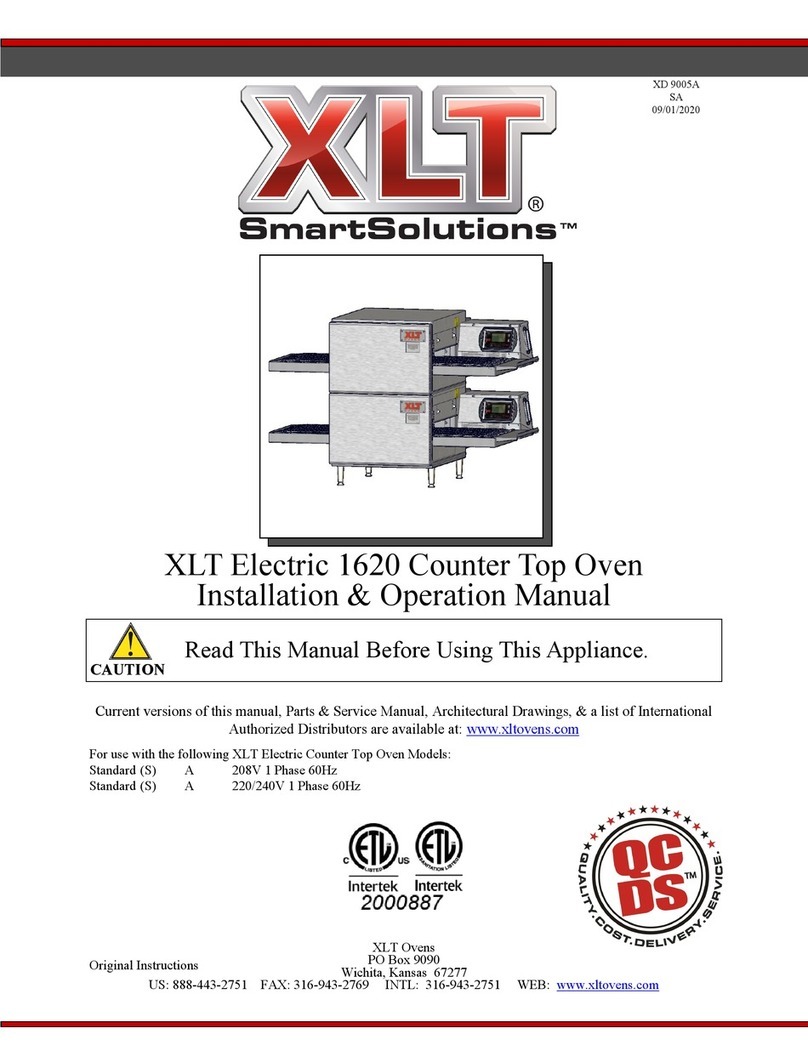
XLT Ovens XLT TS Series User manual

0
Installation & Operation Manual
XLT TS/TS2 Series Conveyorized Oven
This appliance is for professional use by qualified personal. This appliance
must be installed by qualified persons in accordance with the regulations in
force. This appliance must be installed with sufficient ventilation to prevent
the occurrence of unacceptable concentrations of substances harmful to
health in the room in which it is installed. This appliance needs an
unobstructed flow of fresh air for satisfactory combustion and must be
installed in a suitably ventilated room in accordance with current
regulations. This appliance should be serviced by qualified personnel at
least every 12 months or sooner if heavy use is expected.
XD9 1 -TS
Rev D - 7/2 8
© 2 8 BOFI Inc.
BOFI
™
P. O. Box 9 9
Wichita, KS 67277
Phone: 1-316-943-2751
Fax: 1-316-943-2769
www.xltovens.com

XD9010 TS Rev D 7/2008
Installation & Operation Manual
1
WARNING & SAFETY INFORMATION
• Post in a prominent location instructions to be followed in the event you smell gas. This
information can be obtained by consulting your local gas supplier.
FOR YOUR SAFETY
Do not store or use gasoline or other flammable
liquids or vapors in the vicinit of this or an other appliance.
WARNING: Improper installation, adjustment, alteration, service or maintenance can
cause propert damage, injur , or death. Read the installation, operating and maintenance
instructions thoroughl before installing, using, or servicing this equipment.
• In the event a gas odor is detected, shut off the gas at the main shutoff valve immediately.
Contact your local Gas Company or supplier.
• Do not restrict the flow of combustion and/or ventilation air to the unit. Provide adequate
clearance for operating, cleaning, and maintaining the unit and adequate clearance for
operating the gas shutoff valve when the unit is in the installed position.
• Keep the area free and clear of combustible material.
• Ovens are certified for installation on combustible floors.
An electrical schematic is located inside the control box of the oven and on pages 29 31
of this manual. Disconnect input power to the unit before performing any maintenance.
• This unit requires a type II ventilation hood, which has make up and exhaust air to ensure
adequate air supply. The installation should conform to local codes and the National Fire
Protection Association Code, ANSI/NFPA 70, and the National Electrical Code.
• This unit may be operated with either natural gas or propane fuel as designated on the
nameplate label located on the back of the unit.
• This unit must be operated by the same voltage, phase, and frequency of electrical power as
designated on the nameplate label located on the back of the unit.
Minimum clearances must be maintained from combustible and noncombustible construction
materials. See spacing information on page 18.
• Follow all local codes when installing this unit. In the absence of local codes, the installation
must conform to the National Fuel Gas Code, ANSI Z223.1, latest version, Natural Gas
Installation Code, CAN/CGA B149.1, or the Propane Installation Code, CAN/CGA B149.2,
as applicable.
• Follow all local codes to electrically ground the unit. The installation must conform to the
National Electrical Code, ANSI/NFPA 70, or the Canadian Electrical Code, CSA C22.2, as
applicable.
• PLEASE RETAIN THIS MANUAL FOR FUTURE REFERENCE.

XD9010 TS Rev D 07/2008 2
Installation & Operation Manual
Y
our new XLT oven is the result of our dedication to help you produce the finest quality
baked goods. XLT ovens are designed and manufactured by BOFI, a subsidiary of Wolfe
Electric, Inc., which was founded in Wichita, Kansas shortly after WW II. In addition to
ovens, Wolfe Electric also makes fan blades & blower wheels, metal coil handling
equipment, and other diversified products.
BOFI has made a substantial and growing investment in capital equipment and facilities,
including state of the art CAD/CAM designing and fabricating software and machine tools.
The company has also developed ways to build quality into its products at each stage of the
manufacturing process, both through extensive use of automation and, most importantly,
through an awareness that people are the central element in quality control.
BOFI is dedicated to serving your needs. Your complete satisfaction with your oven is our
goal. We are available 24/7/365 to assist you with all of your maintenance and service
requirements. If a problem arises we ask that you simply call us at (316) 943 2751. We will
promptly initiate steps to solve your problem. We will ask for the following information:
Your name, address, and telephone number
Model number and serial number of the unit (found on the right hand side of the oven)
Details of the concern
BOFI wants you to be totally satisfied with every aspect of owning and using your XLT oven.
Your feedback, both positive and negative, is very important to us as it helps us understand
how to improve our products and our company. Our goal is to provide you, our customer,
with an oven that we can be proud to build and you can be proud to own.

XD9010 TS Rev D 7/2008
Installation & Operation Manual
3
TABLE OF CONTENTS
1. DESCRIPTION......................................................................................................................4
2. OPERATOR CONTROLS ....................................................................................................6
3. OPERATION.......................................................................................................................10
3.1. CONDENSED START UP INSTRUCTIONS ................................................................10
3.1.1. FOR THE 1832 TS/TS2, 2440 TS/TS2, 3240 TS/TS2 AND 3255 TS/TS2
MODELS ............................................................................................................................... 10
3.1.2. FOR THE 3270 TS/TS2 AND 3870 TS/TS2 MODELS ......................................... 10
3.2. DETAILED START UP INSTRUCTIONS.....................................................................11
3.3. SHUT DOWN INSTRUCTIONS.....................................................................................12
4. SPECIFICATIONS..............................................................................................................13
5. INSTALLATION.................................................................................................................17
5.1. INSTALLATION OVERVIEW .......................................................................................17
5.2. PURCHASER’S RESPONSIBILITY ..............................................................................17
5.3. ASSEMBLY INSTRUCTIONS .......................................................................................17
5.4. PHYSICAL LOCATION & SPACING REQUIREMENTS............................................18
5.5. ELECTRICAL SUPPLY ..................................................................................................18
5.6. GAS SUPPLY ..................................................................................................................18
5.7. CASTERS.........................................................................................................................19
5.8. RESTRAINT ....................................................................................................................19
5.9. VENTILATION................................................................................................................19
5.9.1. VENTILATION REQUIREMENTS ........................................................................ 19
5.9.2. VENTILATION GUIDELINES ............................................................................... 20
5.9.3. VENTILATION PERFORMANCE TEST............................................................... 20
5.9.4. HOOD INTERCONNECTION ................................................................................ 21
5.9.5. FIRE SUPPRESSION............................................................................................... 21
5.10. MAINTENANCE .............................................................................................................23
5.11. CLEANING ......................................................................................................................23
6. TOUBLESHOOTING..........................................................................................................25
6.1. COOKING PROBLEMS..................................................................................................25
6.2. OVEN PROBLEMS .........................................................................................................26
7. ROUGH IN..........................................................................................................................27
8. ELECTRICAL DIAGRAMS:..............................................................................................29
8.1. 1832 TS/TS2, 2440 TS/TS2, 3240 TS/TS2, & 3255 TS/TS2.........................................29
8.2. 3270 TS/TS2 & 3870 TS/TS2 LEFT HAND SIDE.........................................................30
8.3. 3270 TS/TS2 & 3870 TS/TS2 RIGHT HAND SIDE ......................................................31
9. WARRANTY ......................................................................................................................32

XD9010 TS Rev D 07/2008 4
Installation & Operation Manual
1. DESCRIPTION
The XLT TS/TS2 series of ovens consist of six models; the 1832 TS/TS2, the 2440 TS/TS2,
3240 TS/TS2, the 3255 TS/TS2, the 3270 TS/TS2, and the 3870 TS/TS2. The first two
digits of the model number represent the conveyor width, and the second two digits indicate
the bake chamber length. Ovens with a longer bake chamber length have a higher cooking
capacity. The TS/TS2 designation represents the fact that the ovens are triple stackable. The
ovens may be used in a single oven stack, a double oven stack, or a triple oven stack. A
single stack or double stack oven can be upgraded by adding another oven deck or two up to
the maximum of three. All ovens are gas fired and are available in Natural gas or LP
(Propane) gas models. (Electric ovens are also available). The 3270 TS/TS2 and
3870 TS/TS2 models have two burners, one right hand and one left hand. They also have
two control boxes, again one right and one left. The other models have only a single right
hand burner with a single right hand control box. All models can have the optional split belt
conveyor.
Figure 1: Examples of Single Double and Triple Stack Ovens
Food product is placed on the stainless steel wire conveyor belt on one side of the oven. The
conveyor then transports the food through the bake chamber at a user controlled speed. This
provides repeatable and uniform food cooking. The conveyors can be easily configured to
move either left to right or right to left. A large center sandwich door allows the
introduction or removal of food items for cooking at shorter times. Temperatures up to
550°F inside the oven are achieved by means of a user adjustable digital control.
An easily removable front panel allows the full cleaning of the oven interior. All exposed
oven surfaces both exterior and interior are constructed of stainless steel. The conveyor is a
one piece design and is removed from the right side of the oven. No tools are required for
disassembly and cleaning of the conveyor or oven interior. The oven itself is mounted on
lockable swivel casters for easy moving and maintenance. Examples of single, double and
triple stack ovens are shown in Figure 1. An oven drawing with nomenclature is shown in
Figure 2.

XD9010 TS Rev D 7/2008
Installation & Operation Manual
5
Figure 2: TS/TS2 Front View
Figure 3: Right Hand Control Box
(All Models)
Figure 4: Left Hand Control Box (3270-TS/TS2
and 3870-TS/TS2)

XD9010 TS Rev D 07/2008 6
Installation & Operation Manual
2. OPERATOR CONTROLS
The operator controls for the ovens are located on the
Control Box which is on the right side of the oven. The
fan, burner, and conveyor switches with the operating
instructions are shown in Figure 5. Also nearby are the
temperature control, the conveyor control, and the fuse
bank, (see Figure 6).
The 3270 TS/TS2 and 3870 TS/TS2 ovens have an
additional Control Box on the left side, (see Figure 7).
The duplicate oven Switch Panels on these models
allow the oven to be operated from either side of the
oven.
Figure 5: Oven Switch Panel

XD9010 TS Rev D 7/2008
Installation & Operation Manual
7
Figure 6: Right Hand Side Control Panel (All Models)
All XLT ovens have a right hand side Control Panel. The fuses are located on the Control
Panels and are labeled for their function and replacement part number. It is very important to
use only the fuses listed. Using larger or smaller fuses than what is labeled on the oven can
cause serious damage to the operator and/or the oven and will also void any and all
warranties. See Figure 6.
A conveyor control is located at the top of the panel, and a temperature control is located
mid panel. A cooling fan with washable filter is near the bottom of the panel. The filter is
held in place by a snap on fan guard.

XD9010 TS Rev D 07/2008 8
Installation & Operation Manual
Figure 7: Left Hand Side Control Panel (3270-TS/TS2 and 3870-TS/TS2)
3270 TS/TS2 and 3870 TS/TS2 ovens also have a left hand side Control Panel. This panel
houses the fuses for the equipment inside the left hand control box. A second temperature
control is also used for controlling the burner on the left half of the oven. This allows for two
different temperature zones within these ovens for cooking flexibility, with a maximum
delta of 50º F. Another cooling fan is near the bottom of the panel. See Figure 7.

XD9010 TS Rev D 7/2008
Installation & Operation Manual
9
Figure 8: Optional Right Hand Control Panel (Split Belt Conveyor)
A popular option on the XLT oven is the split conveyor belt. This allows for 2 different
conveyor speeds through the oven. Figure 8 shows the right hand control panel when the
split belt option is present. The difference is that a second conveyor control is also present.

XD9010 TS Rev D 07/2008 10
Installation & Operation Manual
3. OPERATION
The XLT oven is a convection oven. It cooks foods by forcing hot air to circulate around the
food, thereby increasing the heat transfer rate. Convection ovens generally cook foods faster
than conventional ovens. The XLT oven models also have a conveyor that carries food
through the oven at a uniform rate. This helps eliminate under or over cooking food.
3.1. CONDENSED START-UP INSTRUCTIONS
3.1.1. FOR THE 1832-TS/TS2 2440-TS/TS2 3240-TS/TS2 AND 3255-TS/TS2
MODELS
1. Turn the FAN switch ON (see Figure 5).
2. Adjust the temperature controller set point to the desired temperature
3. (see Figure 6).
4. Turn the BURNER switch ON (see Figure 5).
5. Observe the indicated temperature for one minute. You should hear the burner ignite
and the temperature should rise after 30 45 seconds.
6. If the burner does not ignite, turn the BURNER switch OFF, wait FIVE (5) minutes,
and repeat steps 3 & 4.
7. Turn the CONVEYOR switch ON (see Figure 5).
8. Adjust the conveyor controller to desired belt time (see Figure 6).
9. Allow about 30 minutes for the oven to reach desired operating temperature.
This oven is not capable of being safely placed in operation in the event of a power
failure. No attempt should be made to operate this oven during power failure.
3.1.2. FOR THE 3270-TS/TS2 AND 3870-TS/TS2 MODELS
1. Turn both LH & RH FAN switches ON (see Figure 5).
2. Adjust both of the temperature controller set points to the desired temperatures (see
Figure 6).
3. Turn both the BURNER switches ON (see Figure 5).
4. Observe the indicated temperature for one minute. You should hear the burners ignite
and both of the temperatures should rise after 30 45 seconds.
5. If one or both of the burners do not ignite, turn one BURNER switch OFF, wait FIVE
(5) minutes, and repeat steps 3 & 4.
6. Turn both of the CONVEYOR switches ON (see Figure 5).
7. Adjust both of the conveyor controllers to desired belt times (see Figure 6).
8. Allow about 30 minutes for the oven to reach desired operating temperature.
This oven is not capable of being safely placed in operation in the event of a power
failure. No attempt should be made to operate this oven during power failure.

XD9010 TS Rev D 7/2008
Installation & Operation Manual
11
3.2. DETAILED START-UP INSTRUCTIONS
1. Turn the Fan switch on (see Figure 5). This turns on a fan that forces air onto the
food item and also turns on the temperature control/display.
2. Adjust the temperature controller set point to desired temperature.
Figure 9: Temperature Controller
See Figure 9 above to adjust the temperature controller. To change the oven Set Point
temperature, press and hold either the Up or Down key for 2 seconds and then use
these 2 keys to adjust to the desired temperature. After “Up or Down” key press
inactivity, the display will blink once indicating that the set point temperature has
been set. The Func and Man keys are used at the factory to program the variables in
the controller. These variables can be viewed but are locked in memory by an
internal switch. It is recommended that the Func and Man keys be left alone. If either
of these keys has been pressed, simply press them again until the display matches the
above Figure 9. It may take several key presses to cycle through all the variables.
3. Turn the Burner switch on (see Figure 5). The Fan switch must be on and the fan
must be operating properly in order for the burner to fire. For the 3270 TS/TS2 and
3870 TS/TS2 models, both Burner switches must be on.
4. Allow about 30 45 seconds for the burner to fire.
5. If the burner does not ignite, turn the Burner switch off, wait five (5) minutes, and
repeat steps 3 & 4.
6. Turn the Conveyor switch on (see Figure 5). For the 3270 TS/TS2 and 3870 TS/TS2
models, both Conveyor switches must be on.

XD9010 TS Rev D 07/2008 12
Installation & Operation Manual
7. Adjust the Conveyor Control to the desired belt time. The Conveyor Control will
display the belt time. The Up or Down key will adjust the time accordingly. See
Figure 10 below. The Enter key is used to program the controller at the factory and is
disabled by an internal switch.
Figure 10: Conveyor Control Display
These controls are factory preset at 4:00 minutes minimum and 10:00 minutes
maximum. If a belt time is desired that is outside these limits, contact BOFI for
proper service procedures.
8. Allow 30 minutes for warm up.
3.3. SHUT DOWN INSTRUCTIONS
To turn the oven off, just turn the three switches off (Fan, Burner, & Conveyor, see
Figure 5). Do not unplug the oven from electrical power. The oven is equipped with an
automatic cool down feature that allows the fan to run until the oven is cooled to a safe
level (approximately 20 30 minutes). Note that for the 3270 TS/TS2 and 3870 TS/TS2
ovens either side control panel can be used to turn the oven on or off.

XD9010 TS Rev D 7/2008
Installation & Operation Manual
13
4. SPECIFICATIONS
Figure 11: Oven Size Specification Drawing

XD9010 TS Rev D 07/2008 14
Installation & Operation Manual

XD9010 TS Rev D 7/2008
Installation & Operation Manual
15
GENERAL SPECIFICATIONS
Oven ELECTRICAL REQUIREMENTS
Single Stack Volts Amps Phase Frequency
1832-TS/TS2 6
244 -TS/TS2 6
324 -TS/TS2 6
3255-TS/TS2 6
327 -TS/TS2 1
387 -TS/TS2
12 VAC
1
Single 6 Hz
Double Stack Volts Amps Phase Frequency
1832-TS/TS2 12
244 -TS/TS2 12
324 -TS/TS2 12
3255-TS/TS2 12
327 -TS/TS2 2
387 -TS/TS2
12 VAC
2
Single 6 Hz
Triple Stack Volts Amps Phase Frequency
1832-TS/TS2 18
244 -TS/TS2 18
324 -TS/TS2 18
3255-TS/TS2 18
327 -TS/TS2 3
387 -TS/TS2
12 VAC
3
Single 6 Hz
GAS REQUIREMENTS (INLET)
Oven
Single Stack
Natural Gas
(6"- 8" WC)
Propane Gas
(11"- 14" WC)
1832-TS/TS2 6 , Btu 6 , Btu
244 -TS/TS2 75, Btu 75, Btu
324 -TS/TS2 1 , Btu 1 , Btu
3255-TS/TS2 16 , Btu 16 , Btu
327 -TS/TS2 18 , Btu 18 , Btu
387 -TS/TS2 18 , Btu 18 , Btu
Oven
Double Stack
Natural Gas
(6"- 8" WC)
Propane Gas
(11"- 14" WC)
1832-TS/TS2 12 , Btu 12 , Btu
244 -TS/TS2 15 , Btu 15 , Btu
324 -TS/TS2 2 , Btu 2 , Btu
3255-TS/TS2 32 , Btu 32 , Btu
327 -TS/TS2 36 , Btu 36 , Btu
387 -TS/TS2 36 , Btu 36 , Btu
Oven
Triple Stack
Natural Gas
(6"- 8" WC)
Propane Gas
(11"- 14" WC)
1832-TS/TS2 18 , Btu 18 , Btu
244 -TS/TS2 225, Btu 225, Btu
324 -TS/TS2 3 , Btu 3 , Btu
3255-TS/TS2 48 , Btu 48 , Btu
327 -TS/TS2 54 , Btu 54 , Btu
387 -TS/TS2 54 , Btu 54 , Btu
GAS ORIFICE SIZES (per oven)

XD9010 TS Rev D 07/2008 16
Installation & Operation Manual
Oven
Natural Gas
Main
Orifice ID
Pilot
Orifice ID
Pilot
Pressure
Manifold
Pressure
1832-TS/TS2 .14 "
244 -TS/TS2 .156"
324 -TS/TS2 .182"
3255-TS/TS2 .234"
327 -TS/TS2 .173"
387 -TS/TS2 .173"
. 18” 3.5” WC 3.5" WC
GAS ORIFICE SIZES (per oven)
Oven
Propane Gas
Main
Orifice ID
Pilot
Orifice ID
Pilot
Pressure
Manifold
Pressure
1832-TS/TS2 .156"
244 -TS/TS2 . 96"
324 -TS/TS2 .11 "
3255-TS/TS2 .144"
327 -TS/TS2 .1 4"
387 -TS/TS2 .1 4"
. 18” 5.5” WC 1 . " WC
NOTE: For proper operation, measure the gas pressure, (see Figure 12), with all gas appliances,
such as furnace, hot water heater, oven(s), etc., a) off and b) with all gas appliances on.
Figure 12: Gas Pressure Check
Contact BOFI, a factory representative, or a local service company to make all gas pressure
adjustments.

XD9010 TS Rev D 7/2008
Installation & Operation Manual
17
5. INSTALLATION
5.1. INSTALLATION OVERVIEW
The following is an overview of the installation process.
1. Read this manual thoroughly.
2. Make sure all electric, gas, and ventilation utilities are adequately sized and in place
before the oven arrives.
3. Inspect the oven and crates for freight damage upon arrival. Assemble the oven on its
base near the area of intended usage. Remove all combustibles and obstructions from
the area.
4. Have your plumber make all gas connections per local building codes. Provide
adequate clearance to access the gas shut off valve. Check for leaks!
5. Have your electrician make all electrical connections per local codes. Provide
adequate clearance to access the electrical plug and receptacle.
6. Install a restraint device and make sure that it guards against transmission of strain to
the gas line and electric cord.
7. Test the exhaust hood using a smoke candle to determine the amount of combustion
products removed.
5.2. PURCHASER’S RESPONSIBILITY
Note: All installations must conform to local building and mechanical codes.
It is the responsibility of the purchaser:
1. To see that the gas and electric utilities are installed on site in accordance with local
mechanical codes and with the specification in this manual.
2. To unload, uncrate, move, and assemble the oven(s) in their intended location.
3. To see that the gas and electric utilities are connected properly and using the proper
hardware by a qualified installer.
5.3. ASSEMBLY INSTRUCTIONS
These ovens come completely assembled from the factory except for the Back Wall
Stand offs and Product Stops. Back wall stand offs are attached to the conveyor belt for
shipping purposes only. They must be removed prior to oven start up. The stand offs
are designed to provide adequate clearance between the back of the oven and a wall. To
assemble the stand offs, loosen the appropriate bolts in the back wall and insert the
stand off tab underneath the flat washers of the back wall bolts. Tighten the bolts. The
product stops are shipped loose inside the oven. Remove them prior to start and install
on the exit end of the conveyor. Detailed assembly instructions are available, contact
XLT Customer Service.

XD9010 TS Rev D 07/2008 18
Installation & Operation Manual
5.4. PHYSICAL LOCATION & SPACING REQUIREMENTS
It is best to install ovens adjacent to a wall. It is possible to install an oven in the middle
of a room, but due to the routing of gas and electric lines, and ventilation hood
performance, these installations can be more costly. The utility rough in information is
shown on page 27.
These ovens are suitable for installation on combustible floors. The minimum clearance
from the back is 6" and is determined by the back wall standoffs that are included with
the oven. The standoffs are intended for use with either combustible or noncombustible
walls. The minimum side clearances are 6". See Section 7. Rough In for gas and
electrical connections.
5.5. ELECTRICAL SUPPLY
All XLT ovens require a 120VAC power supply. See General Specifications Chart for
the electrical power requirements.
WARNING
Electrical Grounding Instructions
This appliance is equipped with a three-prong (grounding) plug for our protection
against shock hazard and should be plugged into a properl grounded three-prong
receptacle. Do not cut or remove the grounding prong from this plug.
When installed, the appliance must be electrically grounded in accordance with local
codes, or in the absence of local codes, with the National Electrical Code, ANSI/NFPA
70, or the Canadian Electrical Code, CSA C22.2, as applicable.
5.6. GAS SUPPLY
The gas supply shall have a gas meter and regulator large enough to handle all of the gas
appliances, such as the furnace, hot water heater, and oven(s), in operation at the same
time. Add up all of the Btu ratings to determine the total load.
The installation must conform with local building codes, or in the absence of local
codes, with the National Fuel Gas Code, ANSI Z223.1, latest version, Natural Gas
Installation Code, CAN/CGA B149.1, or the Propane Installation Code, CAN/CGA
B149.2, as applicable, including:
1. The appliance and its individual shutoff valve must be disconnected from the gas
supply piping system during any pressure testing of that system at test pressures
in excess of ½ psi (3.45 kPa).
2. The appliance must be isolated from the gas supply piping system by closing its
individual manual shutoff valve during any pressure testing of the gas supply
piping system at test pressures equal to or less than ½ psi (3.45 kPa).

XD9010 TS Rev D 7/2008
Installation & Operation Manual
19
5.7. CASTERS
Because the oven(s) are equipped with casters, the installation must be made with a
connector that complies with the Standard for Connectors for Moveable Gas Appliances,
ANSI Z21.69 or Connectors for Moveable Gas Appliances CAN/CGA 6.16, and a
quick disconnect device that complies with the Standard for Quick Disconnect Devices
for Use With Gas Fuel, ANSI Z21.41, or Quick Disconnect Devices for Use With Gas
Fuel, CAN1 6.9.
5.8. RESTRAINT
For all installations, a restraint must be provided to limit the movement of the oven
without depending on the gas connector and the quick disconnect device or its
associated piping, and/or the electric cord, to limit the oven movement. The restraint
must be connected to the eye bolt which is supplied with the oven. The eye bolt is in the
lowest hole in the back wall on the control end of the oven. Upon completion of
performing any service functions that require removal of the restraint, insure that it is
correctly re attached to the oven (see Figure 15). One restraint is required per oven
stack.
Figure 13: Restraint view
5.9. VENTILATION
5.9.1. VENTILATION REQUIREMENTS
Most gas burning appliances produce carbon monoxide, a poison. This and the heat
generated must be vented to the outside. A ventilation hood is required to remove the
heat and products of combustion. The hood and HVAC installation must meet local
building and mechanical codes. Requirements vary throughout the country depending
This manual suits for next models
1
Table of contents
Other XLT Ovens Commercial Food Equipment manuals