XMark Fitness XM-7626.1 User manual

Owner’s Manual
XM-7626.1
FUNCTIONAL TRAINER
10/20

Table Of Contents
2
Important Safety Information
Before You Start
Assembly
Parts List
Exploded View
3
4
5-16
17
18

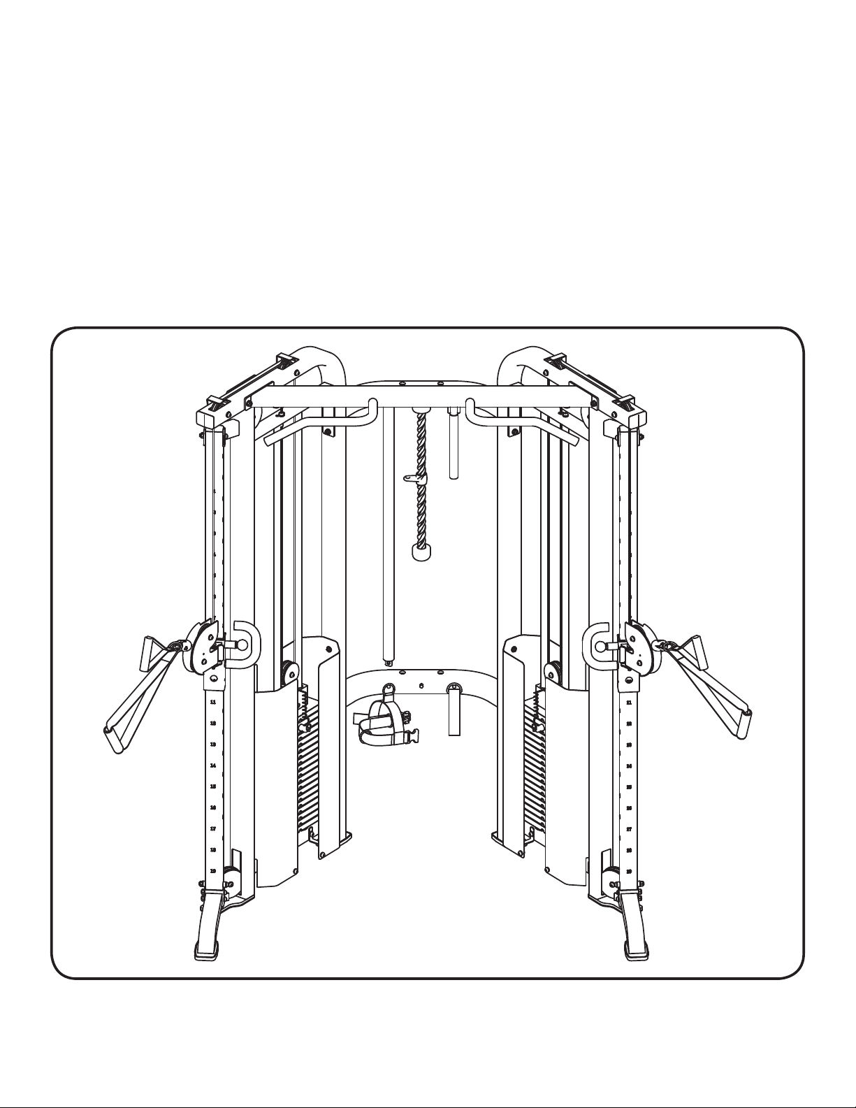
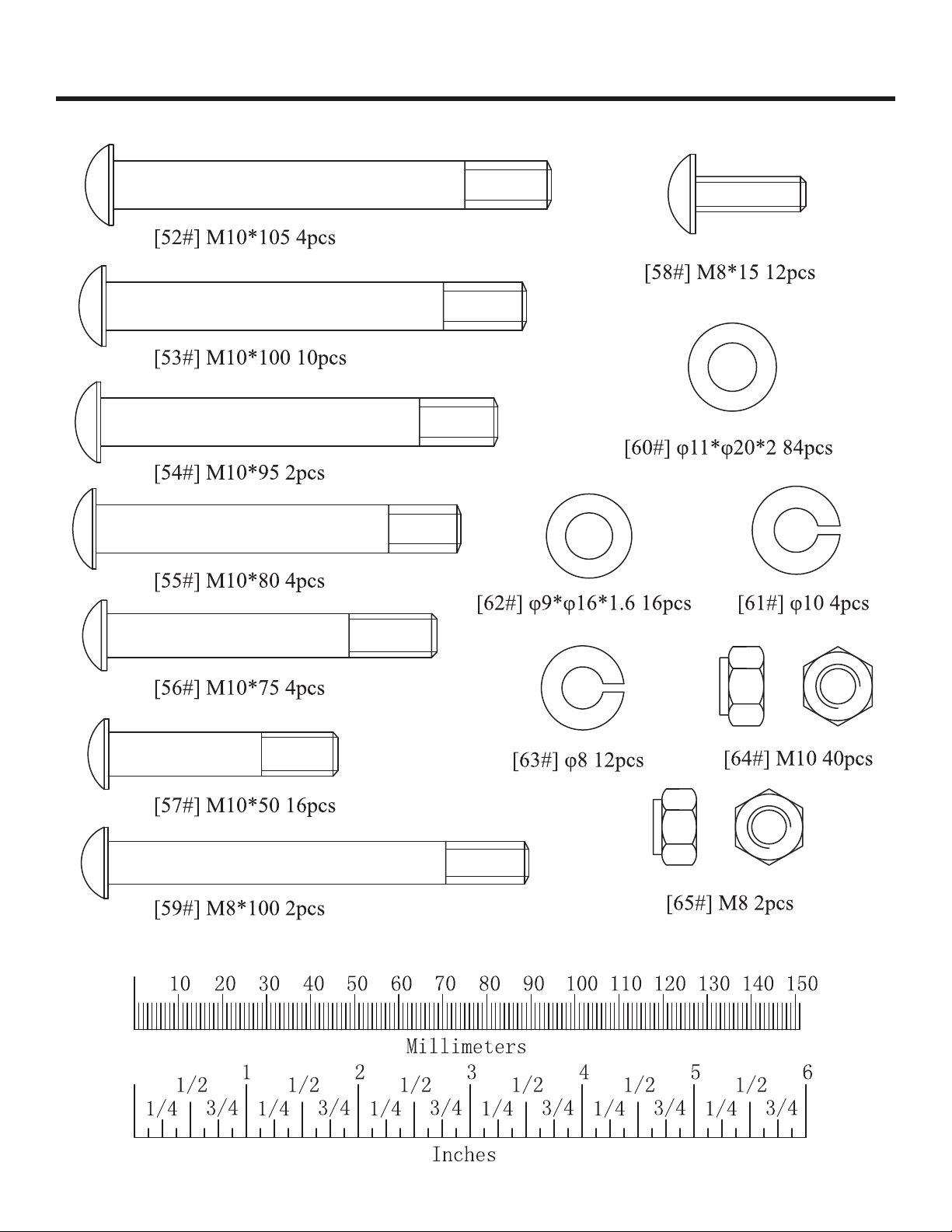
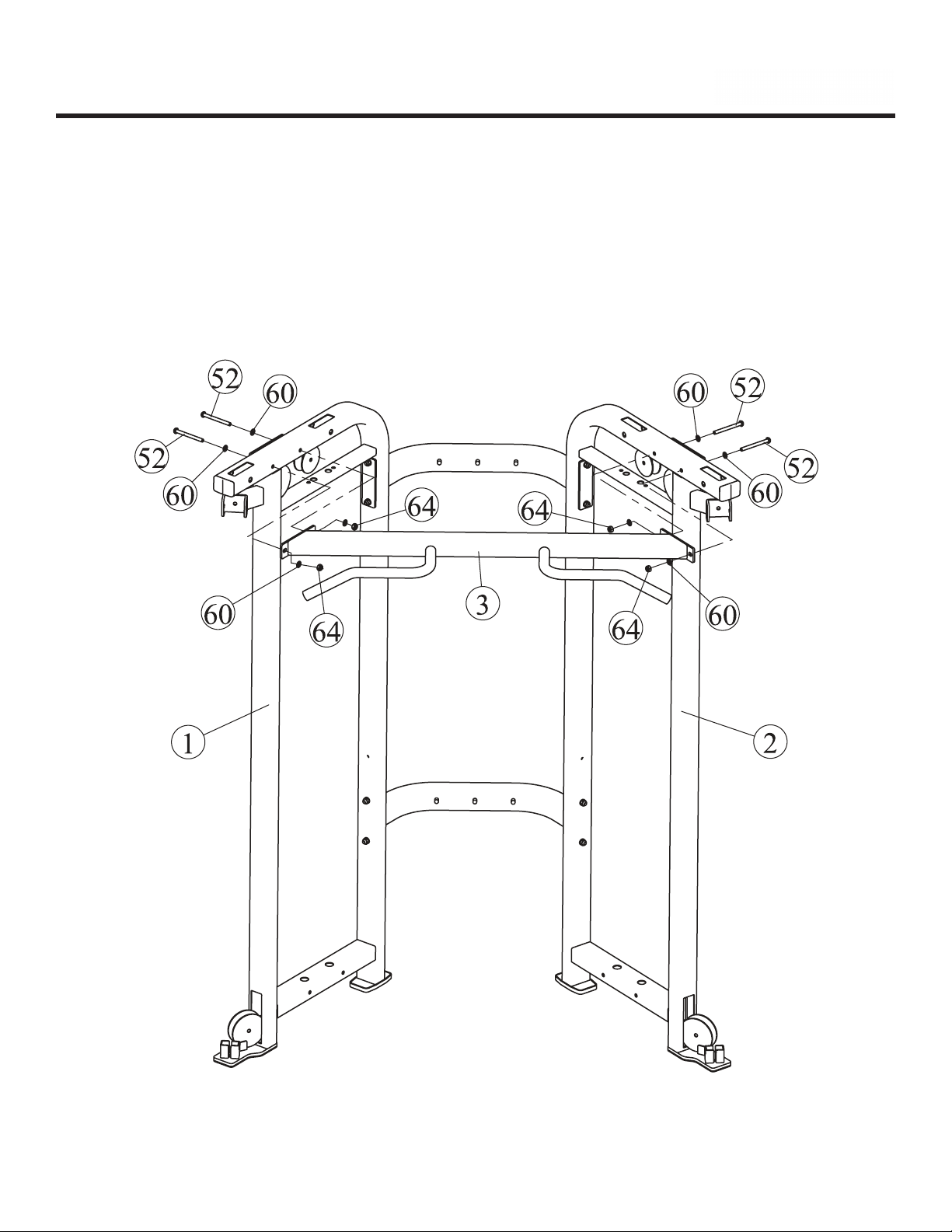
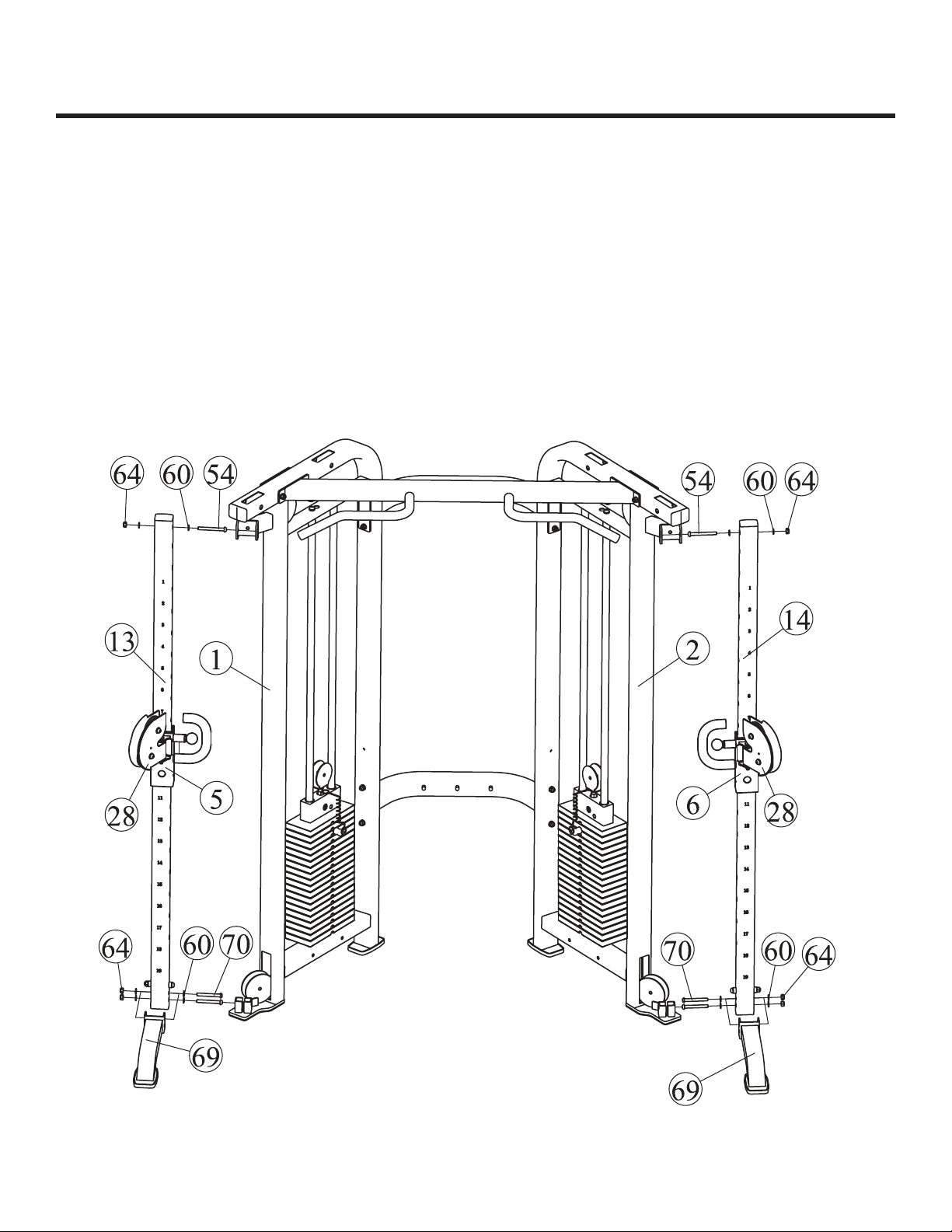
Prior to assembly, remove components from the box and verify that all the listed
parts were supplied.
SAFETY INFORMATION WARNING!
Before using this unit or starting any exercise program, consult your physician.
This is especially important for persons over the age of 35 and/or persons with pre-
existing health problems. XMark assumes no responsibility for personal injury or
property damage sustained by or through the use of this product.
It is the owner’s responsibility to ensure that all users of this unit have read the
Owner’s Manual and are familiar with safety information and precautions.
SAFETY PRECAUTIONS
•This unit should only be used on a level surface and is intended for indoor use
only. XMark recommends an equipment mat be placed under the unit to protect
the floor or carpet and for easier cleaning.
•Walking or running shoes and the appropriate clothing should be worn when using
this unit
•Always examine your unit before using to ensure all parts are in working order.
•Do not leave children unsupervised near or on the unit.
•Service to your unit should only be performed by an authorized service represen-
tative, unless authorized and/or instructed by a XMark technician. Failure to
follow these instructions will void the warranty.
Important Safety Information
3

Before You Start
QUESTIONS?
EMAIL: [email protected]
THANK YOU for making this unit a part of your exercise
program.
XM
ark assures the very best in value, appearance,
durability and biomechanics.
This manual will guide you through the assembly process. If at any time you
are having trouble with the assembly or use of this product, then please contact
us at
take care of you, our valued customer.
'
4

Assembly
5

Assembly
•2 x Button Head Cap Screw (#55)
•4 x Button Head Cap Screw (#56)
•16 x Flat washer (#60)
•8 x Nylon lock nut (#64)
6
S
TE
P
1
:
Connect Left Frame (#1) and the Right Frame (#2) with two Rear beam (#4) using:
Wrench Tighten the bolts before moving to the next step
2 or more people are required. This makes the process of assembly faster and safer.

Assembly
7
•4 x Button Head Cap Screw (#52)
•8 x Flat washer (#60)
•4 x Nylon lock nut (#64)
S
TE
P
2
:
Connect Main Top Beam (#3) and the Left Fram e (#1) and Right Frame (#2) using:
Wrench Tighten the bolts before moving to the next step

Assembly
Repeat this step to complete the right side.
8
•2 x Button Head Cap Screw (#57)
•2 x Spring Washer (#61)
•2 x Flat Washer (#60)
S
TE
P
3
:
Slide Weight Bumpers (#37) onto Guide Rods (#19) and place into Left Frame (#1)
Hand tighten hardware for the rest of the assembly
Slide 19 Weight Plates (#40) onto Guide Rods (#19) with pin slot facing inward.
Slide Top Plate (#34) onto Guide Rods (#19) with pin slot facing inward.
Attach Pulley Bracket (#30) and Weight Pin (#38) to the Top Plate (#34)
Secure Guide Rods (#19) to the Left frame (#1) using:
Threaded end of Guide Rods should be on top.

Assembly
9
- The holes on the Slip tubes will be facing the inside of the unit.
Attach the Left Slip Tube (#13) and the Front Support Frame (#69) to
the Left frame (#1) using:
Repeat this step to complete the right side.
•2 x Button Head Cap Screw (#70)
•1 x Button Head Cap Screw (#54)
•6 x Flat Washer (#60)
•3 x Nylon Lock Nut (#64)
S
TE
P
4
:
Attach Left Slip Frame (#5) onto the Left Slip Tube (#13)

Assembly
S
TE
P
5
:
Lower the threaded end of one Pulley Cable (#8)
down the Left Frame (#1)
Retrieve the threaded end of the Pulley Cable (#8) from the
bottom of the Left Frame (#1)
Attach the threaded end of the Pulley Cable (#8) to the Left
Slip Frame (#5)
10

Assembly
•1 x Button Head Cap Screw (#57)
•1 x Nylon lock nut (#64)
•2 x Flat washer (#60)
•4 x Flat washer (#60)
•2 x Button Head Cap Screw (#57)
•2 x Nylon lock nut (#64)
Repeat these stepsto complete the right side.
11
S
TE
P
6
:
Attach two 4.5" Pulleys (#33) to the Left Frame (#1) using:
•2 x Button Head Cap Screw (#57)
•4 x Flat Washer (#60)
•2 x Nylon Lock Nut (#64)
These pulleys go where the cable was routed in the STEP 5. The cable will route beneath the
bottom 4.5" pulley and above the upper 4.5" pulley. The upper pulley will slide through the
smaller bracket next to it to fit into place.
STEP 7
:
Attach three Small Pulleys (#32) to the Left Frame (#1) using:
•1 x Button Head Cap Screw (#57)
•2 x Button Head Cap Screw (#53)
•6 x Flat Washer (#60)
•4 x Longer Pulley Spacer (#7)
•2 x Cable Retainer Bracket (#16)
•3 x Nylon Lock Nut (#64)
STEP 8
:
Attach one Small Pulley (#32) to the Pulley Bracket (#30) using:
STEP 9
:
Attach two Small Pulleys (#32) to the Double Pulley Bracket (#28) using:

Assembly
Cable Assembly Exploded View
12
Cable Assembly Parts List
Ref # Description
1
2
3
4
5
6
7
8
Cable
Protect Jacket
Cushion Cover
Cable Adapter
Chain
Axle Bolt
Nylon Lock Nut
Hex Nut
Cable Routing
:
Before the cable can be routed, the
cable assembly will need to be temporaly disassembled.
1. Unscrew the Axel Bolt
2. Detach the Cable Adapter
3. Slide off the Cushion Cover
4. Remove the Protect Jacket

Complete cable routing as shown below
END
START
Cable routes above the Frame. Not
doing so can damage the cable.
Rea
ss
e
m
ble
Cable
Assembly:
1. Add the Protect Jacket
2. Slide on the Cushion Cover
3. Attach the Cable Adapter
4. Screw on the Axel Bolt
13

Assembly
Repeat this step to complete the right side.
14
S
TE
P
10
:
Attach four Shroud Brackets (#12) to the Left Frame (#1) using:
•2 x Button Head Cap Screw (#53)
•4 x Flat Washer (#60)
•2 x Nylon Lock Nut (#64)
Attach two Weight Shroud (#11) to the Left Frame (#1) using:
•6 x Button Head Cap Screw (#58)
•6 x Flat Washer (#62)
•6 x Spring Washer (#63)
S
TE
P
11
:
Snap eight Hole Plugs (#72) to the two Rear Beams (#4)

Weight Stack Sticker Placement
10
20
30
40
50
60
70
80
90
100
110
120
130
140
150
160
170
180
190
200
200 LB Stack
15
The weight stack image below illustrates how the weight stack decals should be
applied to the weight stack. Please note these decals should not be put on until the
entire unit has been assembled and all bolts and nuts have been tightened.

Assembly
Tighten all hardware securely.
You have completed the assembly of your new XM-7626.1.
Congratulations!
16
Lubricant
: Apply to guide rods if friction occurs. Never put lubricant on the cables.
Touch Up Paint
: A small bottle of gray touch up paint is provided if you ever scratch your machine.

Parts List
1
2
3
4
5
6
7
8
9
10
11
12
13
14
15
16
17
18
19
20
21
22
23
24
25
27
28
29
30
31
32
33
34
35
36
37
38
40
42
43
44
45
46
47
48
49
50
51
52
53
54
55
56
57
58
59
60
61
62
63
64
65
66
67
68
69
70
71
72
73
1
1
1
2
1
1
8
2
2
2
4
8
1
1
4
4
1
1
4
1
2
1
1
1
1
1
2
2
2
2
12
4
2
2
2
4
2
38
4
2
2
4
4
2
2
3
4
4
4
10
2
4
4
16
12
2
84
4
16
12
40
2
1
1
1
2
4
1
1
1
P00251
P00252
P00253
P00254
P00255
P00256
P00257
P00258
P00259
P00260
P00261
P00262
P00660
P00661
P00263
P00264
P00265
P00266
P00267
P00268
P00098
P00269
P00270
P00271
P00652
P00112
P00162
P00203
P00164
P00106
P00533
P00654
P00640
P00125
P00641
P00585
P00326
P00324
P00138
P00249
P00202
P00541
P00184
P00429
P00163
P00149
P00542
P00565
P00590
P00589
P00616
P00613
P00612
P00605
P00635
P00633
P00134
P00130
P00136
P00133
P00561
P00564
P00560
P00022
P00679
P00662
P00614
M00004
H00023-1
H00023-2
Frame, Left XM-7626
Frame, Right XM-7626
Beam, Main Top XM-7626
Beam, Rear XM-7626
Frame, Slip Left XM-7626
Frame, Slip Right XM-7626
Spacer, Pulley Longer XM-7626
Cable, Pulley XM-7626
Handle Grip Top XM-7626
Grip Handle Slip XM-7626
Shroud, Weight XM-7626
Bracket, Shroud
Tube Slip Left XM-7626
Tube Slip Right XM-7626
Stopper, Rubber XM-7626
Bracket, Cable Retainer XM-7626
Pad, Big Base Right XM-7626
Pad, Big Base Left XM-7627
Guide Rod, XM-7626
Strap, Leg Extension/Curl
Handle, Long Strap XM-7626
Rope, Tricep
Bar, Sport XM-7626
Grip, Sport Bar XM-7626
Bar, Long XM-7626
Ankle Strap
Bracket, Double Pulley XM-7626
Pop Pin XM Series
Pulley Bracket w/ Shaft XM-7626
Hand Strap
Small Pulley
Big Pulley 4.5"
Top Plate
Screw M12*35
Selector Rod
Weight Bumper
Weight Pin
Weight Plate 10LB
Glide Sleeve
Plug 50.8*76.2
Plug 38*63.5
Round Plug 25
Base Pad
Jam Nut 1/2"-12
Shaft, Pulley Bracket XM-7626
Gear Hook
Bronze Bushing, ID16
Spacer Nylon
Button Head Cap ScrewM10*105
Button Head Cap ScrewM10*100
Button Head Cap ScrewM10*95
Button Head Cap ScrewM10*80
Button Head Cap Screw M10*75
Button Head Cap ScrewM10*50
Button Head Cap ScrewM8*15
Button Head Cap Screw M8*100
Flat Washer Φ11*Φ20*2
Spring Washer 10
Flat Washer, Φ9*Φ16*1.6
Spring Washer 8
Nylon Lock Nut M10
Nylon Lock Nut M8
Hex Key 6
Wrench 17-19
Lubricant
Front Support Frame
Button Head Cap Screw M10*85
Owner's Manual XM-7626
Bolt Pack 1, XM-7626
Bolt Pack 2, XM-7626
XM-7626 Parts List
Ref # Part #
Description Qty
17

Exploded View
18

Customer Service: 1-800-719-4605
Table of contents