4
Navigating
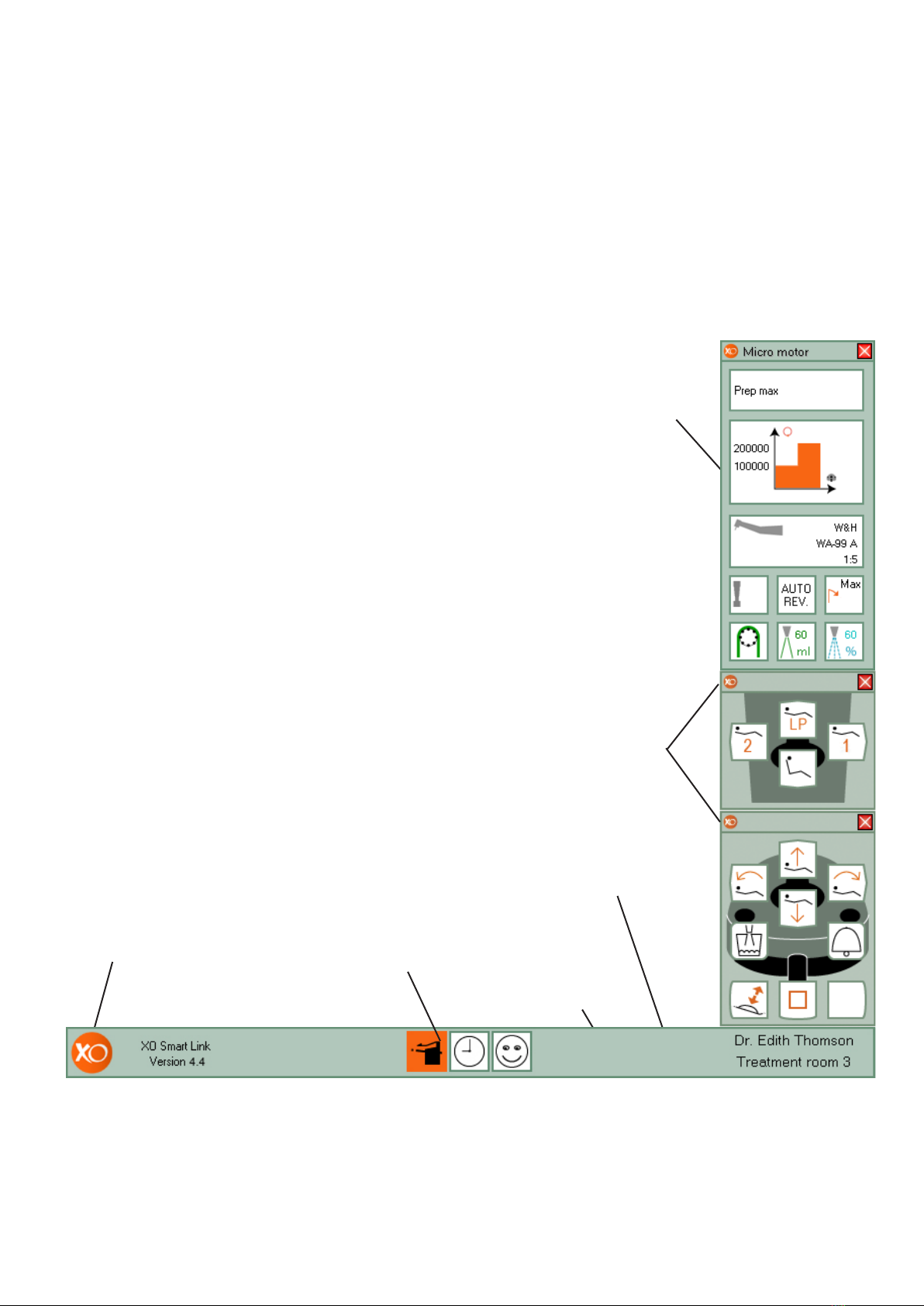
XO Smart
Link
Navigating
using short-
cuts
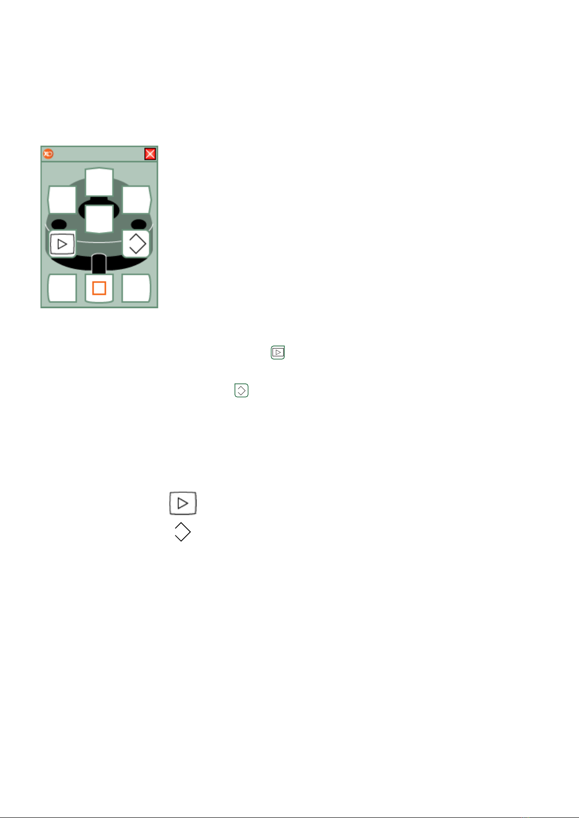
The main tools for navi-
gating XO Smart Link
are foot control and XO
Bar.
XO Bar contains a num-
ber of cells:
• Each cell represents a
plug-in - when all unit
instruments rest.
• Each cell represents a
unit instrument pro-
gram - when a unit
instrument is
lifted forward.
A cell may be active ,
selected ,
or non selected .
The active cell defines
the function of foot con-
trol (and joystick).
XO Screen User Guide
shows how foot control
(and joystick) functions
in accordance with the
active cell.
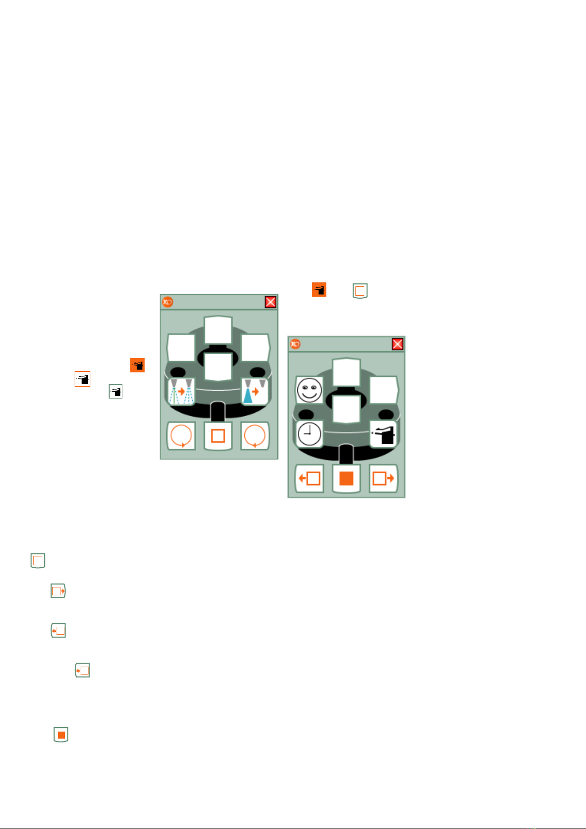
Deactivate a cell with
.
Select the rightward cell
with .
Select the leftward cell
with .
When the leftmost cell is
selected will select
the rightmost cell and
vice versa.
Activate a selected cell
with .
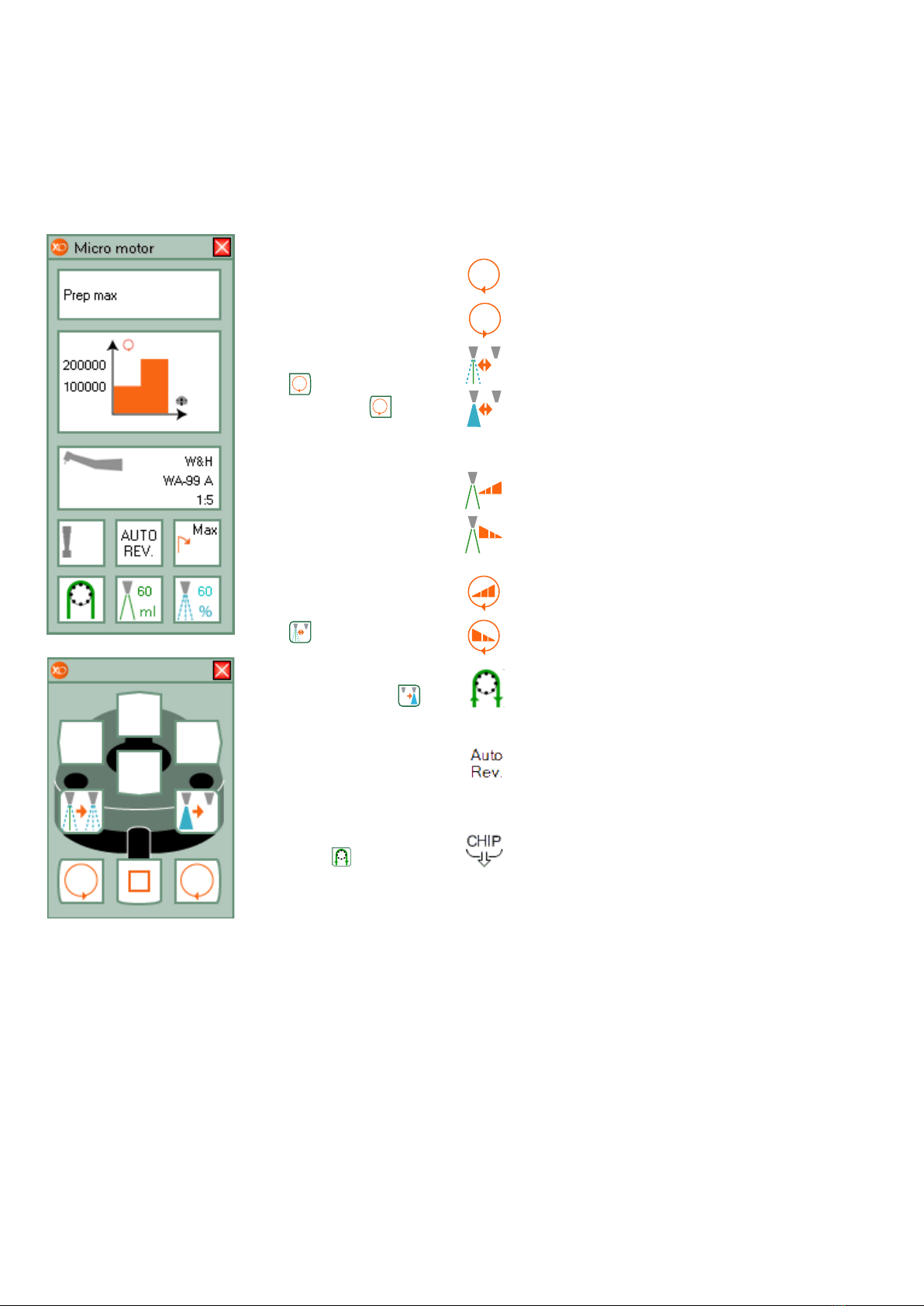
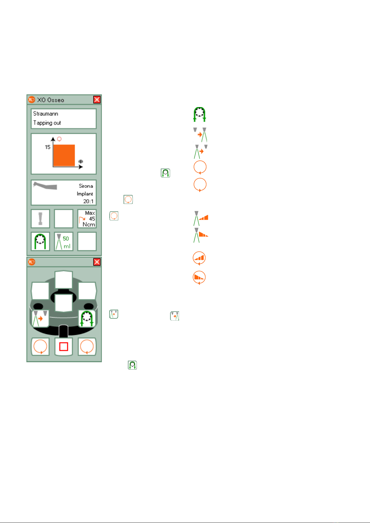
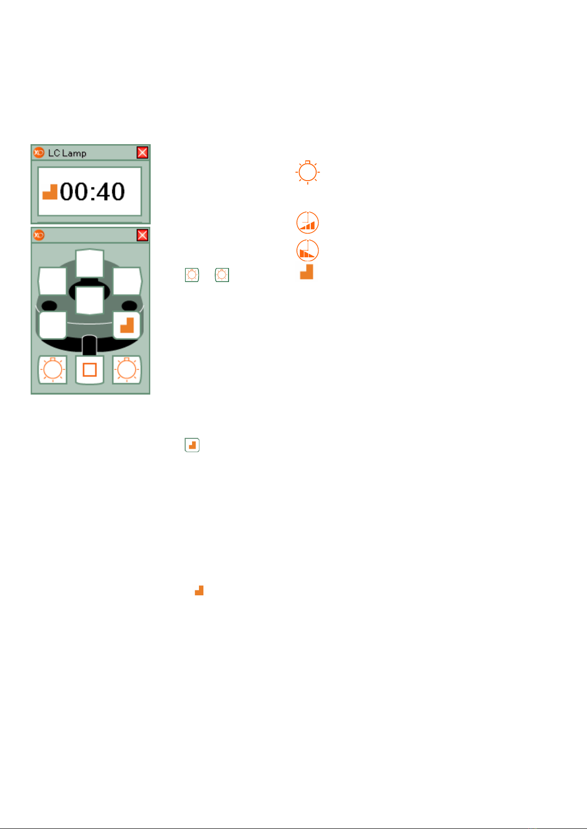
XO Screen
User Guide
Each cell of XO Bar de-
fines the function of foot
control (and joystick).
XO Screen User Guide
shows you the available
functions.
Example of XO Screen
User Guide when using
Micro Motor:
When no XO Bar cell is
active shortcuts allow
you to activate
up to 8 different cells:
• With only two foot
control “clicks” and
• Without looking at
the screen.
Deactivate the active
cell with .
Thereafter select a
shortcut:
See page 14 for infor-
mation about configur-
ing shortcuts.