CONGRATULATIONS ONTHE PURCHASE OF YOUR NEW
XPG PYLON BRONZE SERIES POWERSUPPLY UNIT
XPG PYLON BRONZE Series power supplies are created for quiet operation while keeping an
Xtreme power Performance. It features a 120mm Fluid-Dynamic Bearing (FDB) fan running
at extremely low RPM with a fan control circuit design that enables a silent and efficient operation.
80 PLUS BRONZE rated efficiency ensures a low-cost operation and the Fixed cable set provides
user convenience with reasonable length and connector quantity. XPG utilizes only very high
quality 105°C Main Japanese capacitors on all units and it’s a great choice for any high
performance PC that are budget conscious.
SAFETY AND PROTECTION
XPG PYLON has one of the most complete offerings of power safety levels in the industry,
which are listed in detail below.
Note: The main power outputs will be latched off when each protection circuit is triggered. The
main output can be reset by power-cycling the DC remote on/off or the AC power. +5Vsb output
is set to auto-recovery when the fault condition is removed.
INTEGRATED PROTECTION CIRCUITS
Over Current Protection :
XPG follows Intel Power Supply Design Guides with 110%-140% of total current on all +12V,
+5V, and +3.3V rails, therefore the OC P of XPG PYLON is more effective.
Over Voltage Protection :
OVP on +12V, +5V, +3.3V DC output rails are required to comply with the latest Intel ATX Power
Supply Design Guide. OVP shuts down the PS U when the DC outputs exceed a set level, preset
at factory level.
The minimum voltage levels required for compliance are +12V rail@ 15.6V max , +5V rail at 7.0V
max, +3.3V rail at 4.5V max.
Over Power Protection :
XPG follows Intel ATX Power Supply Design Guide with 110-150% of PSU Total Wattage.
Over Temperature Protection :
OTP ensures that the P S U will shut down when the P S U internal temperature reaches a set point.
This is usually as a result of internal current overloading, a defect fan or an abnormal environmental
temperature above the operating temperature range specified for the product.
No Load Operation :
XPG follows Intel ATX Power Supply Design Guide with 0A minimum loading to support
Intel Haswell C6/C7 sleep mode function.
Short Circuit Protection :
SCP is defined as any output impedance of less than 0.1ohms. Among other things, SC P
ensures that the P SU shuts down should any of the rails at +12V, +5V & +3.3V short to any ground,
or to any other rail. It also ensures that no damage should occur to your PC components if there is
any short circuit inside the system.
XPG Power Supplies have full protection circuits on-board to keep your valuable components safe
under all circumstances.
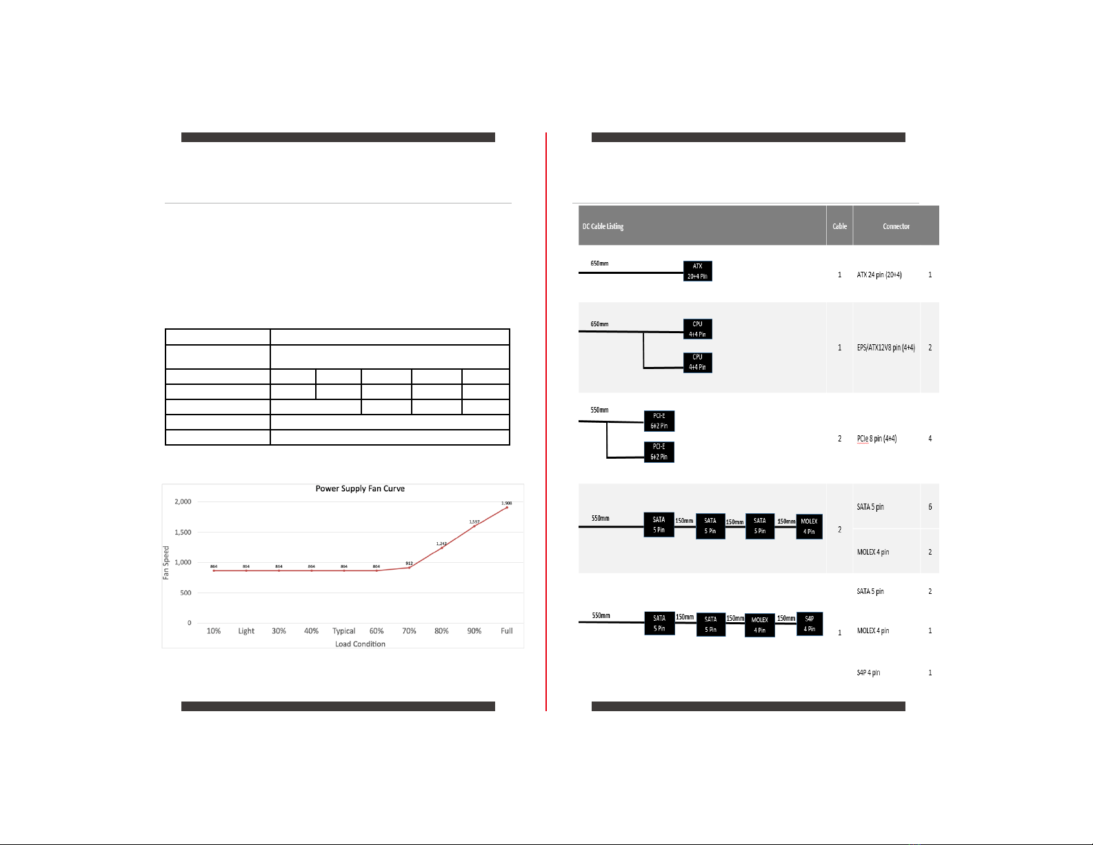
PYLON750BRONZE 5
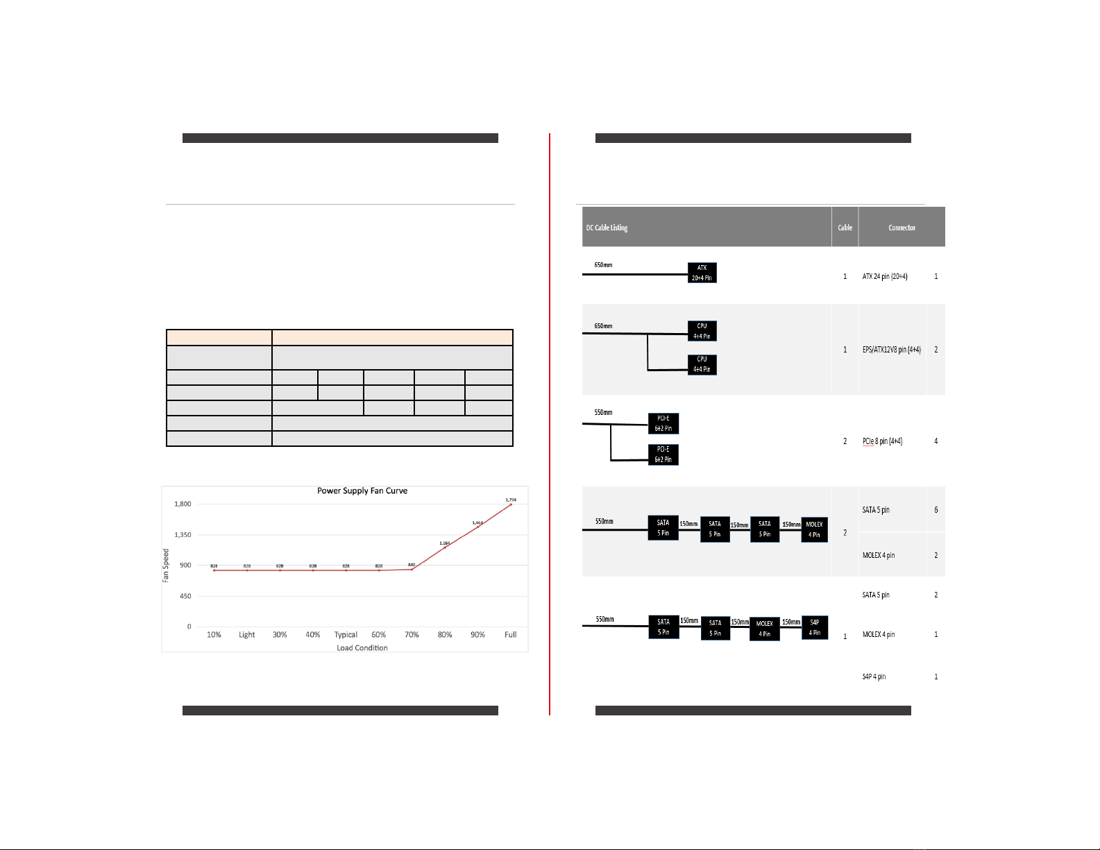
PYLON650BRONZE 7
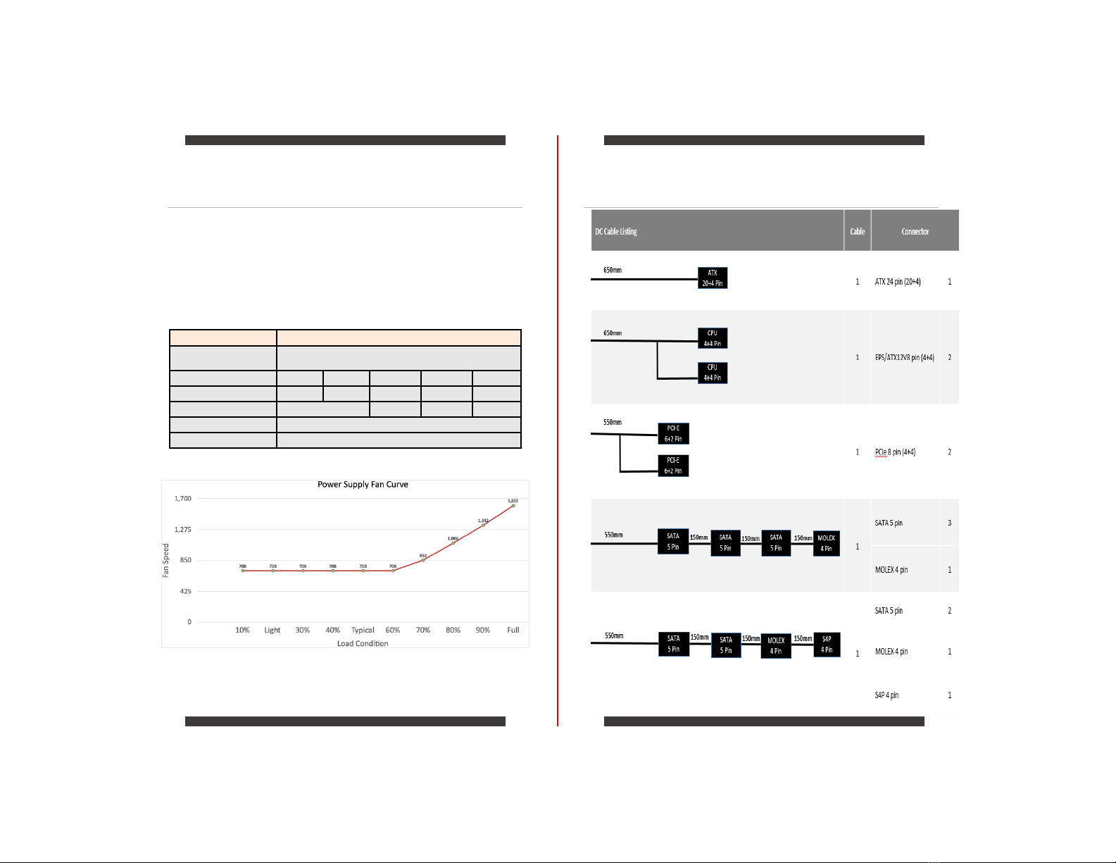
PYLON550BRONZE 9
PYLON450BRONZE 11
Installation 12
Safety and Agency Approvals 13
EN
Product Specifications
03 04