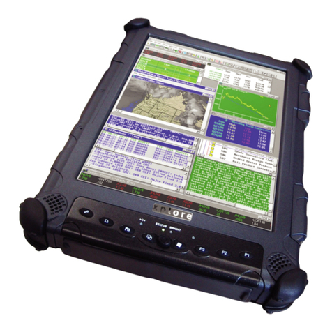
XPLORE TECHNOLOGIES GeneSys User manual

User Guide
GeneSys Pen Tablet Computer

October 2001 Page 2P/N 96-000001-017, Version Q301
Welcome
Congratulations! We are pleased to add you to the growing list of “Xplorers” who have
chosen our innovative GeneSys®Pen Computing System as their mobile computer platform.
The GeneSys®System has been designed, tested and manufactured with a very specific
objective in mind…to meet the needs of today’s mobile workers. The real world offers
environmental and physical challenges that must be met with a mobile computing system
that not only works the way you do, but also can take the abuses of everyday wear and tear.
The GeneSys System design is based upon years of experience in rugged mobile
applications.
Advanced technology, innovative designs and a rugged body are just a few of the highlights
of your GeneSys System. Equally important is Xplore’s commitment to ensuring you are
treated with the same respect and honesty you offer to your customers and peers every day.
Thank you for choosing Xplore and enjoy your journey through our world of mobile
computing.
The Xplore Team

October 2001 Page 3P/N 96-000001-017, Version Q301
Highlights
As one of the most comprehensive wireless pen computing systems available, your GeneSys System
offers innovative features that allow you to take advantage of the most sophisticated application
software and peripheral configurations available.
§High visibility Color LCDs, combined with a unique optics technology provides industry-leading
visibility in challenging lighting conditions including direct sunlight.
§Integrated System that has been designed as a single pen/touch-based mobile computing system
including an innovative Pentium®powered pen computer, comprehensive expansion module(s)
and docking options.
§Performance Driven Design with Intel®Pentium®III 500 MHz processor integrated into a unique
Main Logic Board design which offers Peripheral Component Interconnect (PCI) BUS technology,
256K of L2 Cache, 8MB of Video memory and other “Performance Accelerators”.
§Multimedia Ready System with ATI video controller and Sound Blaster compatible audio
components brings applications to life.
§Rugged Magnesium Housing combined with a patented bumper protection system and
components manufactured for extreme conditions means that the GeneSys is built to last.
§Advanced Resistive Touch Screen provides exceptional accuracy, a brighter and clearer screen
through enhanced light penetration and heightened reliability.
§Adaptable Design, which accommodates multiple PC cards for integrated communication options.
Wireless and peripheral expansion that works with today’s technology and can accommodate the
new technology of tomorrow.
§Rugged Quick Release Docks provide a secured, mechanical docking system that ensures
positive docking and overall reduction in stress on the docking connectors.
§Dual USB ports are protected in a recessed portion of the patented bumper system and provide
instant connectivity to a growing universe of USB compliant peripherals.
As you “Xplore” your GeneSys Mobile Computing System, you will discover many performance-based
features. A number of accessory and peripheral options are also available to support your entire
system.
Please note: Xplore Technologies®Corp. and its 100% owned subsidiaries, Xplore Technologies®
Corporation of America or Xplore Technologies International may be referenced throughout this manual
by various names such as Xplore, XPLORE, Xplore Technologies, etc. Please consider these references
interchangeable.

October 2001 Page 4P/N 96-000001-017, Version Q301
Regulatory Notices
FCC (Notice for users in the United States of America and Canada.)
WARNING –FCC Regulations state that any unauthorized changes or modifications to this
equipment not expressly approved by the manufacturer could void the user’s authority to operate this
equipment.
The GeneSys computer and the Quick Release docking station comply with Part 15,
Class B of the FCC Rules. Operation is subject to the following two conditions: (1) this device may not
cause harmful interference, and (2) this device must accept any interference received, including
interference that may cause undesired operation.
This Class B digital apparatus meets all requirements of the Canadian Interference-Causing
Equipment Regulations.
Trade Name: Xplore Technologies ® Corp.
Model: GeneSys®II and GeneSys®Maximus
Responsible Party: Xplore Technologies ® Corp.
11675 Jollyville Road, Suite 150, Austin Texas, 78759
Attention: VP of Engineering
This personal computer system consists of the following components:
Component Supplier Address Model Compliance
Computer Assembly SMTC 15700 Long Vista Drive
Austin, Texas 78728 GeneSys II and
GeneSys Maximus DOC
Computer
Motherboard Delta Electronics, Inc. 186 Ruey Kuang Road, Neihu
Taipei 114, Taiwan, R.O.C. GeneSys DOC
Dock Assembly
Apex Integrated
Manufacturing, Inc. 8006 Cameron Road
Austin, TX 78754 Xpander and Quick
ReleaseDock DOC
Equipment Classification: FCC Class B Assembly
Type of Product: Pen-Based Computer with Intel ® Pentium ® III 500MHz
Processor and Docking System.
Chipset: Intel ® Pentium III uPGA-2
Manufacturer: SMTC, Delta Electronics
CE (Notice for users in the countries that are part of the European Union)
The European Conformity marking on this product means that this product complies with both the
EMC Directive and the Low Voltage Directive of the European Union. Compliance with these
directives implies conformity with the following European Norms:
§EN55022=”Limits and Methods of Measurement of Radio Interference Characteristics for
Information Technology Equipment”
§EN50082-1=”Electromagnetic Compatibility-Generic Immunity Start Part 1: Residential,
Commercial, and Light Industry”
§EN60950=”Safety of Information Technology Equipment”

October 2001 Page 5P/N 96-000001-017, Version Q301
Safety Information
General Information
•Except as described elsewhere in this manual; refer all servicing to qualified personnel.
Immediately shut off the computer and refer for servicing under the following conditions:
•When the power cord or plug is damaged or frayed.
•If the computer has been dropped and the housing has been damaged.
•Turn off the computer and disconnect the AC cord before cleaning.
Battery Information
Handling
•Never put the battery pack in a fire, as it could explode and cause injury.
•Do not attempt to open or alter the battery pack.
•Do not allow liquids to come in contact with the battery pack.
•Do not solder to the battery terminals.
•Remove battery from system before shipping or storing.
Charging
•Charge the battery pack only with the AC and/or DC adapter(s) or desktop chargers provided by
Xplore.
Discharging
•Do not use the battery pack for any purpose other than powering the GeneSys computer.
Storage
•Store the battery pack in a cool and dry place.
•Recharge the battery pack after storage, before use.
•If the GeneSys is scheduled to be away from a power source (AC or DC) for any length of time,
please remove the battery pack from the GeneSys and properly store it until further use is
required.
Conditioning
•Must be conditioned prior to initial use to ensure optimal battery performance and life.
CAUTION:
If a battery is incorrectly replaced there is danger of explosion. Replace only with the same or
equivalent type recommended by the manufacturer. Discard used batteries according to the
manufacturer’s instructions.
FOR A COMPLETE ELECTRICAL DISCONNECTION, PULL OUT THE AC/DC PLUG AND
REMOVE THE BATTERY.
Copyright
It is the intent of XPLORE that this product be used in full compliance with the copyright laws of the
United States and Canada as well as countries where Xplore is actively selling its products. In
addition, it is also the intent of Xplore that prior permission be obtained from copyright owners
whenever necessary.
Product Information and Customer Assistance
For Product Information and Customer Assistance:
Inside North America Call: 1-888-449-7567 Xplore Technologies Corp.
Outside North America Call: 358-9-8545-800 Xplore Technologies International

October 2001 Page 6P/N 96-000001-017, Version Q301
About this Manual
Disclaimer
This manual has been validated and reviewed for accuracy. The instructions and descriptions it
contains are accurate for the GeneSys Pen Computers at the time of this manual’s production.
However, succeeding computers and manuals are subject to change without notice. Xplore assumes
no liability for damages incurred directly or indirectly from errors, omissions or discrepancies between
the computer and the manual.
Information in this manual is subject to change without notice and does not represent a commitment
on the part of Xplore Technologies Corp. or Xplore Technologies Corporation of America, (“Xplore”).
Xplore shall not be liable for technical or editorial errors or omissions contained herein; nor for
incidental or consequential damages resulting from the furnishing, performance, or use of the
material.
Xplore strongly recommends that separate permanent written records be kept of all important data.
Data may be lost or altered in virtually any electronic memory product under certain circumstances.
Therefore, Xplore assumes no responsibility for data lost or otherwise rendered unusable whether as
a result of improper use, repairs, defects, battery replacement, use after the specified battery life has
expired, or any other causes.
Xplore assumes no responsibility directly or indirectly, for financial losses or claims from third persons
resulting from the use of this product and any of its functions, such as stolen credit card numbers, the
loss or alteration of stored data, etc.
Last Revised: October 2001.
Copyright
© 1997, 1998, 1999, 2000, 2001 Xplore Technologies Corp. All rights reserved. Under the
copyright laws, this manual cannot be reproduced in any form without the prior written permission of Xplore. No patent liability
is assumed, with respect to the use of the information contained herein.
GeneSys User Guide –2nd Edition, October 2001
Trademarks
XploreTechnologies®and GeneSys®are registered trademarks of Xplore Technologies Corporation of America.
Intel®Pentium®is a registered trademark of Intel®Corporation.
IBM and PS/2 are trademarks of International Business Machines Corporation.
Microsoft, MS-DOS, Windows, and the Windows Logo are trademarks of Microsoft Corporation.
All other brand and product names not mentioned here, but referenced throughout this document are trademarks or registered
trademarks and are the property of their respective holders.
Warranties
Xplore’s Standard Limited Warranty included with every shipment applies to all Xplore products. No other Warranties, whether
implied or actual, will be authorized by Xplore.
October 2001 Page 7P/N 96-000001-017, Version Q301
General Precautions
Xplore computers are designed to optimize safety, minimize strain and withstand the rigors of
portability. However, certain precautions should be observed to further reduce the risk of personal
injury or damage to the computer.
Be certain to read the general precautions below and to note the cautions included in the text of the
manual.
Heat Injury
Avoid prolonged physical contact with the exposed metal surfaces on the front and back of the
computer. If the GeneSys computer is used for long periods, its surface can become warm. While the
temperature may not feel hot to the touch, if you maintain physical contact with the computer for a
long period of time (if you rest the computer on your lap for a defined period of time, for example)
your skin might suffer low-heat injury.
PC Card Overheating
Some PC Cards (or PCMCIA) can become hot with prolonged use. This is the same for any mobile
computer. If two cards are installed, both can become hot even if only one is used extensively.
Overheating of a PC Card can result in errors or instability in the PC Card operation. Also be careful
when you remove a PC Card that has been used for a long period of time.
Pressure or Impact Damage
Do not apply heavy pressure to the computer or subject it to repetitive strong impacts. Excessive
pressure or impact can cause damage to computer components or otherwise cause malfunctions.
Drops
The GeneSys computer is a full-powered, mobile computer and as such is weighted accordingly.
Although the weight is equally distributed to ensure proper balance, the actual weight of the computer
could cause injury if dropped onto someone’s person. Please take care not to drop the computer on
any vulnerable areas.
Cumulative drops of the computer may result in damage and is not recommended. Continual or
excessive drops due to misuse or abuse will not be covered by Xplore’s warranty program.

October 2001 Page 8P/N 96-000001-017, Version Q301
Contents
Chapter 1: GeneSys System Overview 9
Provides a brief overview of the GeneSys Pen Computer and descriptions of key product features.
Chapter 2: Quick Start 13
Provides step-by-step instructions to help you setup and begin using the computer as quickly as
possible. You should read this chapter first before you undertake any operations.
Chapter 3: Basic Operations 16
Explains the basic operations of power sources, pen and touch inputs and peripheral connections.
Chapter 4: Power Management and Battery 23
Describes how to effectively manage power and use the battery packs.
Appendices 27
Provides advice on the routine care and maintenance of the computer, technical specifications, and
how to run the setup utility to change system settings.
Appendix A: Setup Utility 27
Appendix B: Care and Maintenance 40
Appendix C: Specifications 42
Appendix D: Glossary 43

October 2001 Page 9P/N 96-000001-017, Version Q301
CHAPTER 1
GeneSys Overview
This Chapter provides an overview of your GeneSys Mobile Computer along with a brief description
of key features and functions.
Xplore Your GeneSys
Power Button, Control
Keypad and Indicators The power button is located on the membrane keypad. In addition, the keypad has screen
brightness control buttons as well as indicators for Pow er, Docking, Battery and Hard Drive
activity. Also, a hidden PC speaker provides basic system sounds. See Chapter 3 for more
details.
Display Screen The LCD displays high-contrast text and graphics. See Appendix for specifications.
USB Host Port A USB host is also called a “root” and controls all traffic on the bus. It is typically
implemented as a separate peripheral device with a cable that plugs into a port on the hub.
Can also act as a hub. An example would be a USB floppy drive.
AC/DC Input JackThe AC and/or DC adapter plugs connect to this socket. Use only the model of adapter that is
supplied by Xplore. Using the wrong adapter can damage your computer.
USB Hub Port Hubs are wiring concentrators and enable the multiple attachment characteristics of the USB.
Each hub converts a single attachment point into multiple attachment points. Hubs can detect
attach and detach at each downstream. An example would be a USB hub port used to
connect multiple USB devices.
Docking Locator Pads These are rubber pads designed to protect the top and bottom of your computer and to assist
you in properly docking your computer. More detail is provided later in this manual.
Logo Plate This is the plate where the Xplore Technologies brand logo is placed.
Rubber Grips The rubber grips are provided to aid in shock protection of your computer and to provide a
tactile, ergonomic surface for holding your computer. Facing the front of the computer, the
upper left and both right hand grips are assembled at the factory andshould not be removed.
The lower left grip is removable in order to access the battery compartment. See procedure
for accessing the battery later in this manual.
Rubber
Grips
(Right & Left
Sides)
Power Button, Control
Keypad & Indicators
Docking Locator Pads
(Top & Bottom)
Display
Screen
Logo
Plate
Power Jack and
USB Ports
USB Host Port
AC/DC Input Jack
USB Hub Port
GeneSys II
Figure 1.1 –Front and Right Side View of GeneSys II

October 2001 Page 10 P/N 96-000001-017, Version Q301
Power Button, Control
Keypad and Indicators The power button is located on the membrane keypad. In addition, the keypad has screen
brightness control buttons as well as indicators for Power, Docking, Battery and Hard Drive
activity. Also, a hidden PC speaker provides basic system sounds. See Chapter 3 for more
details.
Display Screen The LCD displays high-contrast text and graphics. See Appendix for specifications.
USB Host Port A USB host is also called a “root” and controls all traffic on the bus. It is typically
implemented as a separate peripheral device with a cable that plugs into a port on the hub.
Can also act as a hub. An example would be a USB floppy drive.
AC/DC Input Jack The AC and/or DC adapter plugs connect to this socket. Use only the model of adapter that is
supplied by Xplore. Using the wrong adapter can damage your computer.
USB Hub Port Hubs are wiring concentrators and enable the multiple attachment characteristics of the USB.
Each hub converts a single attachment point into multiple attachment points. Hubs can detect
attach and detach at each downstream. An example would be a USB hub port used to
connect multiple USB devices.
Docking Locator Pads These are rubber pads designed to protect the top and bottom of your computer and to assist
you in properly docking your computer. More detail is provided later in this manual.
Rubber Grips The rubber grips are provided to aid in shock protection of your computer and to provide a
tactile, ergonomic surface for holding your computer. Facing the front of the computer, the
upper left and both right hand grips are assembled at the factory and should not be removed.
The lower left grip is removable in order to access the battery compartment. See procedure
for accessing the battery later in this manual.
Rubber
Grips
(Right & Left
Sides)
Power Button, Control
Keypad & Indicators
Display
Screen
Power Jack and
USB Ports
GeneSys Maximus
Figure 1.2 –Front View of GeneSys Maximus
Docking Locator Pads
(Top & Bottom)

October 2001 Page 11 P/N 96-000001-017, Version Q301
Docking Connector Port This port allowsthe GeneSys computer to dock to the Xpander and Quick Release docking
stations. More details are provided later in this manual.
Sealed Battery
Compartment Located behind the outer lower, left rubber grip is the battery compartment. Instructions are
provided later in this manual.
Product Label This label includes the product brand name and unit serial number as well as bar code.
Certification Label The appropriate emissions and safety certification labels are strategically located on the
back of the tablet in pre-defined cut-outsections.
IRDA Lens Infrared communication device that allows communications with other IRDA devices i.e.
computers, printers, PDAs.
Carry Handle Holes These holes are used to affix the carry handle to the GeneSys tablet.
Guide Pin Holes for
Docking These holes are used as locators to ensure positive docking connections to the GeneSys
docking stations.
Antenna Port Hole
(optional) A cable, upon which an antenna will be mounted, exitsthis hole. This hole is integrated into
the GeneSys tablet when an internal wireless option is ordered.
Docking
Connector Port
Certification
Label
Seale
d Battery
Compartment
Product
Label
Figure 1.3-Back and left side view of GeneSys II
Figure 1.4-Top View of GeneSys II
Guide Pin Holes for Dockin
g
Carry Handle Holes
IRDA Lens
Antenna Port Hole

October 2001 Page 12 P/N 96-000001-017, Version Q301
Key Features
The GeneSys incorporates the following features:
Microprocessor The GeneSys computer is equipped with an Intel Pentium® III processor. It operates at 500MHz
and incorporates a math co-processor and 256K of internal L2 cache memory. A power
management system called ACPI is used to save battery power.
Level 2 Cache A 256KB level 2 cache is provided to maximize performance.
Memory The GeneSys computer comes with 64 Megabytes (MB) of Random Access Memory (RAM),
expandable to 256MB.
Video RAM The GeneSys computer provides 8MB of RAM for video display.
GeneSys II
A 10.4” Ultra Hi-Brite TFT color LCD panel supports high-resolution video graphics and employs a
PCI bus for superior performance.
Display
GeneSysMaximus
A 12.1” Active Transflective color LCD panel viewable in all lighting conditions.
Graphics Controller The graphics controller incorporates the PCI bus to maximize performance and enable flicker-free
display. It also enables up to 16.7 million touches on the computer’s LCD panel.
Digitizer The GeneSys computer has an integrated resistive digitizer that accepts both pen and touch input.
The digitizer is embedded into the glass to maximize performance and accuracy.
Battery Pack A rechargeable Lithium Ion battery pack powers the GeneSys tablet.
Backup Batteries An internal battery backs up the internal Real Time Clock (RTC) and calendar.
Built-in Hard Drive The GeneSys computer has an integrated 2.5” ruggedized hard drive (HDD) with a capacity up to
20 GB.
Docking Interface Port
This port enables connection to any of the GeneSys docking stations and aides further expansion.
Stylus (pen or touch) The stylus is an intuitive input device for operating a computer. It provides the functionality of a
mouse with the familiarity of a regular pen or the touch of a finger. The stylus can be used for
basic pointing and tapping or for handwriting right onto the integrated digitizer.
Plug and Play When you connect an external device to the computer or vehicle dock, Plug and Play capability
enables the system to recognize the connection and makes the necessary configurations
automatically. This feature is effective only with Windows® 9x or 2000.
Special Features
The following features are either unique to the GeneSys or are advanced features, which make the
computer more convenient to use.
Hardware Setup This program lets you customize your hardware settings according to the way you work with your
GeneSys computer and the peripherals you use.
Pen/Touch Utility This program lets you customize your digitizer settings according to the way you work with your
GeneSys computer. The pen/touch interface can be configured by the user to accommodate their
style.
Automatic Display
Standby Power is automatically turned off to the LCD panel when there is no pen, touch or keyboard input
for a time specified in the hardware setup program. Power is restored when the stylus or finger is
touched on the screen or any key on the optional keyboard is pressed. Content is not lost when
display goes into standby mode, however battery performance is improved.
Automatic HDD
Power Off Power is automatically turned off to the hard disk drive when it is not accessed for a time specified
in the hardware setup program. Power is restored when the hard disk is accessed.
Low Battery
Automatic Suspend When battery power is exhausted to the point that the computer operation cannot be continued,
the system provides a visual warning that the battery is low and the system will be shut down. An
audio warning in the form of a beep is also emitted. After approximately 60 seconds, the system
will enter low power state “suspend mode”. It is important to note that AC or DC pow er must be
applied to the unit as quickly as possible after the warning has been issued. Once external power
has been connected, a new fresh battery can be swapped in or the user can continue to use
external power.
Heat Dispersal The Pentium® processor has relatively high power consumption compared to earlier CPU’s.
Therefore, it has greater potential for overheating, especially at higher processing speeds. To
protect from overheating the GeneSys computer uses special materials to move heat away from
the processor to the computer’s case and out into the air. It is normal for the case to become
warm to the touch after prolonged operation, and this is expected as part of a thermal
management system.
Magnesium Housing The GeneSys housing is designed for harsh environments. The metal structure is much stronger
than plastics and provides enhanced protection for the internal electronics.

October 2001 Page 13 P/N 96-000001-017, Version Q301
CHAPTER 2
Quick Start
Your computer is designed and pre-configured for easy setup and use. This chapter describes the
steps you should follow to get your GeneSys System up and running as quickly as possible. You
should read this chapter first. Although many of the instructions and recommendations are common
sense, we want to ensure that you have your GeneSys System configured as quickly as possible.
We recommend that you read the entire manual for a comprehensive overview of the entire GeneSys
system and its operation.
Connecting to AC Power
The rechargeable battery pack, AC adapter or DC adapter can power the computer. See the next
chapter for more information on power sources. The first time you use the computer, be sure to
perform the steps below:
1. Make sure the computer is turned off.
2. Connect the AC adapter cord to the computer.
3. Connect the AC power cord to the AC adapter.
[WARNING] –Always use the AC adapter supplied with the computer. Using other
AC adapters may damage the computer. Always hold the AC adapter cord by its
plug.
4. Plug the AC power cord into a wall outlet.
Figure 2.1 Connecting to AC Power Figure 2.2 Turning Power ON
Note: Alternatively power may be provided by an optional external DC automobile adaptor or
connected directly via the GeneSys Xpander and Quick Release Docks for in-vehicle, forklift or
mobile communication cart installation.
AC Brick/ adapter
Attach AC/DC
Input
Attach cord
set
GeneSys Tablet
GeneSys
Power Controls

October 2001 Page 14 P/N 96-000001-017, Version Q301
Turning Power On
Although we are sure these instructions are unnecessary, we have included these simple instructions
for reasons of completeness. To turn on the power follow these steps:
1. Connect the computer to AC power
2. Press the power button, which is located on the membrane switch (see Chapter 3)
3. Depress the power button for approximately 2 seconds to initiate system response
Note: Do not turn power off immediately after turning on the system. Instead, wait until the operating
system completes booting.
When the power is turned on, the power indicator (on the gray panel above the LCD) lights and the
computer starts.
Adjusting the Screen Brightness
Brightness adjustment buttons have been provided to allow for adjustment for maximum readability.
Removing the Grips
All grips will require minimal effort to remove. However, in the event that the user experiences
difficulty removing any grip, use the follow these steps:
1. Remove the grip above the grip that covers the battery cover (top left grip).
2. Place the edge of the grip on the edge of a table or firm surface (See Figure 3).
3. Slowly but firmly push the tablet down while a table or firm surface supports the edge of the
grip. (See Figure 4).
4. Remove the grip by hand.
Screen
Brightness
Figure 2.3 Screen Brightness Adjustment
for GeneSys II
Figure 2.4 Screen Brightness Adjustment for GeneSys Maximus
Screen
Brightness

October 2001 Page 15 P/N 96-000001-017, Version Q301
Shutting Down the System
To power off the computer, from the Windows 98 or 2000 Start menu, select Shut Down and then
click Okay. The computer shuts down automatically.
Note: If a file is not saved yet, then a dialog box will appear asking you if you want to save the file
or not.
[WARNING]
•Turning off the power without using the Windows Shut Down feature or resetting the
computer may damage or even wipe out the data.
•Before turning the computer back on, wait at least 3 seconds after turning off the computer.
Turning the power off and on in rapid succession can damage the computer’s electrical
circuitry and/or operating system.
Resetting the System
Software Reset
You can reset the software if you encounter software problems, which lock up the computer. To
reset the system or “reboot”, press Ctrl+Alt+Del keys simultaneously (if the optional keyboard is
attached). Then follow the instructions on the screen: press the Ctrl+Alt+Del keys again. The
computer restarts. This is known as a “warm boot”. If you do not have the optional keyboard
attached then use the power button as outlined below.
[WARNING] Resetting may cause data loss. Use the software reset only if the normal Windows
Shut Down does not work because of software malfunction. Although resetting will not damage
the system, you may lose the data you are processing.
Power Button
You can turn off the computer with the power switch if you encounter hardware or software
problems, which lock up the system. Hold the power button for a few seconds and the computer
will shut down.
[WARNING] Before turning the computer back on, wait at least 3 seconds after turning off the
computer. Turning the power off and on in rapid succession can damage the computer’s electrical
circuitry. By tapping the power button in Windows 98 or 2000 will initiate Windows shutdown.

October 2001 Page 16 P/N 96-000001-017, Version Q301
CHAPTER 3
Basic Operations
This chapter describes the basic operations you can perform with your GeneSys Pen Computer.
Tablet Membrane
The GeneSys membrane contains several control options as well as indicators to aid in system
use.
Power Indicator Lets the user know the status of the system; a red light shows when the system is
on or when the system is connected to an external power source.
BatteryIndicator Signals when the battery is in use, being used or is fully charged; a green light
shows when running battery power only and amber when the battery is charging.
Power Button Used to turn the system on or off if the system is locked up.
F2 Function Button Allow for quick access to the bios during bootup; can also be programmed for
Windows applications.
Emergency Panic Button Sends emergency message; can also be programmed for Windows applications
Blackout Screen Button Turns off power to the backlight while the unit remains on.
Screen Brightness Buttons Controls the level of brightness for the screen.
Hard Drive Indicator Lets the user know when the hard disk drive is in use.
Docking Indicator Signals when the system is docked in one of the GeneSys docking solutions.
Power Indicator Lets the user know the status of the system; a red light shows when the system is
on or when the system is connected to an external power source.
BatteryIndicator Signalswhen the battery is in use, being used or is fully charged; a green light
shows when running battery power only and amber when the battery is charging.
Power Button Used to turn the system on or off if the system is locked up.
F2 Function Button Allow for quick access to the bios during bootup; can also be programmed for
Windows applications.
Warm Docking Button Sends emergency message; can also be programmed for Windows applications
Blackout Screen Button Turns off power to the backlight while the unit remains on.
Screen Brightness Buttons Controls the level of brightness for the screen.
Hard Drive Indicator Lets the user know when the hard disk drive is in use.
Docking Indicator Signals when the system is docked in one of the GeneSys docking solutions.
P
ower
F2
Warm
Docking
Screen
Brightness
Figure 3.1 GeneSys
II
Membrane Overview
Screen
Blackout
Power
F2
Warm
Docking
Screen
Brightness
Screen
Blackout
Figure 3.2 GeneSys Maximus Membrane Overview

October 2001 Page 17 P/N 96-000001-017, Version Q301
Programming Function Button
To program the F2 Function Button use the following steps:
1. Create a shortcut for function on the Windows Desktop.
2. Right click on the shortcut icon and select the Properties option.
3. In the Shortcut Key box delete the word None (default option) then while the cursor is still
in the box press the F2 button on the membrane.
4. After this is done F2 should be displayed in the Shortcut Key box. Select the OK or
Apply button to activate this change
Note: If the user wants to change the function key to another function then the current function
must be deleted from the Shortcut Key box. Leave the box blank and press OK or Apply. The
user must re-enter the shortcut for the new function and repeat steps 1-4 for the new function.
Choosing a Power Source
The computer is designed to operate with one of the following power sources:
•AC power from a wall outlet –(external power source 100 to 240 volts).
•DC power from a cigarette lighter in a vehicle –(external power source 11 to 28 volts).
•Lithium Ion battery pack provided with your computer or available as an option.
It is recommended that you use external power whenever possible, relying on the battery pack
only when external power is unavailable or in a mobile only application need.
Using the AC Adapter
The AC adapter provides power for operation and to charge the battery when the AC adapter is
connected to a wall outlet. The AC input voltage can range anywhere from 100 to 240 volts,
making it suitable for use virtually anywhere in the world with the appropriate plug adapter.
The AC power cord provided with the power brick is appropriate for the voltage of your
local area. If you attempt to connect the computer to a wall outlet other than your local
area, check the voltage of the outlet and use an AC power cord appropriate for the outlet.
Using the DC Adapter
The DC adapter provides power for operation and to charge the battery when the DC adapter is
connected to a vehicle cigarette lighter. The DC input voltage can range from 11 to 28 volts,
making it suitable for use in virtually any vehicle. Use only the DC cable supplied by Xplore.
Using the Battery Pack
The rechargeable battery pack allows you to operate the computer without an external power
source. When fully charged, a Li-Ion battery pack can supply power to your computer for up to 4.0
hours (based on APM and normal backlight settings).
The amount of time a battery charge will last depends on the computer’s usage. Applications,
which heavily use the peripherals, like the floppy disk drive, will experience shorter power time.

October 2001 Page 18 P/N 96-000001-017, Version Q301
Charging the Battery
To recharge the battery, connect the AC adapter to the computer as described in the previous
section. The external power source used and whether or not the computer is on influences the
charging of a low battery. Using the Xplore provided AC charger will render charging periods of
about 5 hours when the computer is turned off. When the computer is turned on,fully charging a
low battery will take approximately 13 hours.
Alternatively,you can insert the battery pack into the optional desktop charger. Place the battery
pack into the charger with the contact points in place (the battery will stand vertically). The
battery-charging indicator will light red indicating that the battery is charging. Using the Rapid
Rate desktop charger, approximately 1.5 hours are required to fully charge a low battery. When
the battery is fully charged,the indicator light will turn green.
It is recommended that when you initially receive your GeneSys Pen Computer, you run AC
power to the unit, with the battery installed for a minimum period of 8-10 hours. This will provide
a solid initial charge for your battery.
If you have not used the computer for a long period of time, the battery may become
completelydischarged. In such a case, recharging may take more time than usual.
Important Note: If you are planning to leave your GeneSys Computer idle, away from either an
AC or DC power source, for any length of time, please remove the battery pack from the
computer.
Checking the Battery Level
Check the battery level as follows:
Shut down the unit as per standard shut down procedures and remove the battery from the
battery enclosure. Press the round tab on the battery pack to light the charge bar (only if battery
shipped with GeneSys has this external battery reader-not all are equipped). The green indicator
will identify the approximate charged state of the battery, i.e. 100%, 75%, etc… It is highly
recommended that when your battery meter reads 25% (or one bar), AC or DC power be applied
to the unit in order to recharge the battery. Alternatively, the battery can be removed and
charged in an external desktop charger. The computer may then be turned back on after
connecting to AC or DC power.
Battery power may also be checked using the battery meter in the System Tray. Double tap on
the battery icon on the System Tray, near the clock. A window will appear indicating the
approximate life of the charge and the percentage of charge left in the battery.
Figure 3.3 Two, Battery Power Status Window

October 2001 Page 19 P/N 96-000001-017, Version Q301
The remaining battery amount and remaining time are estimates based upon calculated values. Depending on the actual
usage, the remaining time may be shorter than that indicated.
Using Pen/Touch
In addition to the passive pen, your computer allows you to use your finger as a pointing device.
Most software applications require the use of the “left” mouse button. By tapping on the screen,
your finger, much like the pen, acts as if the left mouse button is being pressed. Your finger or
any other pointing device, will act very much the same. Refer to the Pen instructions below.
Important Note: Please do not use sharp objects or ink-based pens to input to your computer
screen. Damage caused to the screen by inputting via non-approved methods may void the
screen warranty.
Using the Pen
Your computer features a passive pen (stylus) pointing device. The pen combines high-resolution
control and an ergonomic design equally suitable for left-handed and right-handed users. Most
software applications require the use of the “left” mouse button. By tapping on the screen the pen
acts as if the left mouse button is being pressed.
The Pen/Stylus
Figure 3.4 Pen/Stylus
Holding the Pen
Place the pen in your right or left hand in a comfortable writing position.
Move the Pen
The pen acts like an un-tethered mouse. As you move the pen across the display, the pointer on
the screen moves in the same direction across the screen as the pen in your hand. The screen is
very sensitive and will track your movements (you can set this option to your preference, see Pen
Configuration below).
Point and Tap
When you have placed the pen (cursor on the screen) over an icon, menu item or command that
you wish to execute, you can tap on the screen twice rapidly to execute the command. This
procedure is called “point and tap”.
Drag and Drop
You can execute commands or move files by using “drag and drop”. In drag and drop, you
activate a file by pointing and holding the pen down to it. Do not lift the pen. You can then drag

October 2001 Page 20 P/N 96-000001-017, Version Q301
the active file around the screen by moving the pen. When you have placed the file where you
want it, for example in a new directory, lift the pen. The file will drop into the new location.
Right clicking
Using the context sensitive menus available with a “right click” facilitates some applications. Since
the stylus used with the GeneSys is passive, a pen switcher utility has been included to allow
right clicking. Open the PenSwitcher utility from the system tray (See Figure 3.2). The ‘mouse’ will
appear. By tapping on this window the stylus will register the “other” click. When the pen touches
the screen the right click menu will appear. After this the click function will automatically revert
back to the left mouse click setting. The stylus will remain in this mode until the switcher is
clicked again. Note: The color “Red” on the mouse denotes the active button mode.
Figure 3.5 Right-click Mouse Icon in System Tray
Figure 3.6 Normal Left-click Mouse Icon in System Tray
Table of contents
Other XPLORE TECHNOLOGIES Tablet manuals

XPLORE TECHNOLOGIES
XPLORE TECHNOLOGIES iX101T1 Instruction Manual

XPLORE TECHNOLOGIES
XPLORE TECHNOLOGIES iX104 Instruction Manual

XPLORE TECHNOLOGIES
XPLORE TECHNOLOGIES Bobcat Instruction Manual

XPLORE TECHNOLOGIES
XPLORE TECHNOLOGIES iX104-TPC Instruction Manual

XPLORE TECHNOLOGIES
XPLORE TECHNOLOGIES XC6 Instruction Manual

XPLORE TECHNOLOGIES
XPLORE TECHNOLOGIES iX104AtR Instruction Manual

XPLORE TECHNOLOGIES
XPLORE TECHNOLOGIES ix104C2 Instruction Manual

XPLORE TECHNOLOGIES
XPLORE TECHNOLOGIES iX101B1 Instruction Manual

XPLORE TECHNOLOGIES
XPLORE TECHNOLOGIES ix104c4 Instruction Manual