XSY AT Series User manual

Inverter
AT1--Single-phasetothree-phase
AT2--Single-phasetosingle-phase
AT3--Three-phasetothree-phase
AT Simplegeneralseries
High performance and low noise/
Mini AC motordriver

Contents
Chapter 1 Introduction ...................1
Chapter 2Installation and wiring...........2
Portwiring and instructions..............2
Multispeed frequencycomparison table.......4
Basic wiring diagram ....................... 5
Operation panel...........................8
Button instructions
.
.
.. ..........
..
........
9
Button instructions
.
.
.. ..........
..
........
9
Chapter 3Parameterspecification........10
Parameterfunction comparison table... 10
Downtimersetting................... 17
Special parameters forsomemodels....17
Parametersetting method ............ 18
Chapter 4 Fault code....................18
Chapter 5 Qualitycommitment ...........20

Chapter1Introduction
Thismanualisforuserinstallationanddebuggingandroutine
maintenance.
1.Maketheopen-packageinspection.
Pleasecheck:ifproductappearanceisdamagedordeformation;
whetherthecomponentsaredamagedordrop;checkthe
nameplateratingonthecasetoseeifitisyourorder;check
whetherthetimeslistedinthepackinglistarecomplete;please
contactthesupplierimmediatelyiftherearequestionsor
damages.
2.Pleasereadthismanualcarefullybeforeuseandkeepit
properly.
3.Serviceenvironments
PowerSupply
Single
phase
AC
220
V
+
40
%
(for
AT
1
,
AT
2
)
1页
Single
phase
AC
220
V
+
40
%
(for
AT
1
,
AT
2
)
Three-phaseinputAC380V+20%(forAT3)
Temperature:-10℃~50℃
Humidity :0%~65%
4.Mattersneedattention
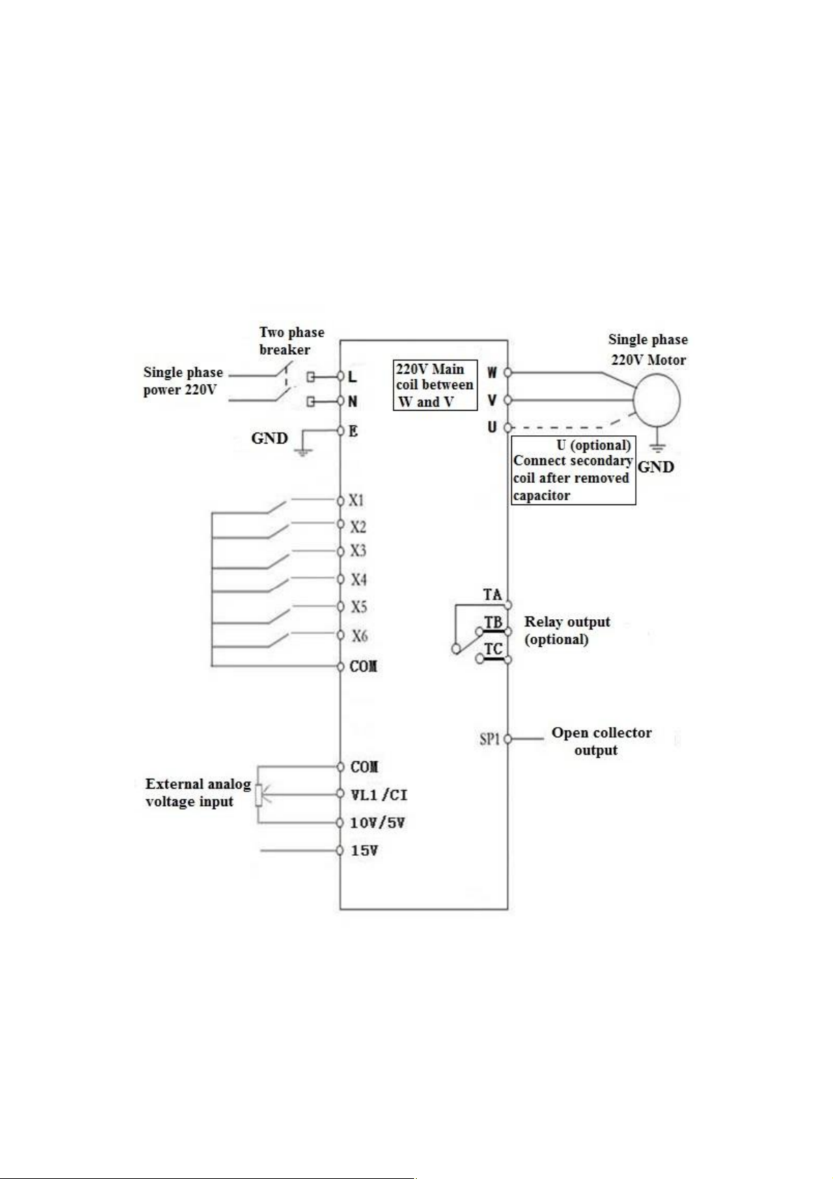
Turnoffthepowersupplywhenconnecting.
MakesurethattheACpowerisnotconnectedtothemotor
output.
5.Usethescenewithoutdew,dust,noncorrosiveliquid/gas.
6.Installationpartsstrong,novibration.
7.Duetothesmallsize,pleasemakesurethewireisconnected
well
8.Ifinhightemperatureenvironment,pleasesetenoughheat
dissipationspace.

1.Maincircuitterminaland function description
(1)Single-phasetothree-phase (for AT1)
Charter 2Installation and wiring
Terminal
label Function description
L,N Singlephase AC220V inputterminal
U,V,W Outputterminalconnect to Three phase
220V
AC
motor
2页
(2)Single-phaseinput and output (for AT2)
220V
AC
motor
GND Grounding terminal
Terminallabel Function description
L,N Singlephase AC220V inputterminal
U,V,W Outputterminalconnect to Single
phase 220V ACmotor
GND Grounding terminal

2.Terminaldescription
Functional
(3). Three-phaseinput and output (forAT3)
Terminal
label Function description
R,S,T Three phase AC380V inputterminal
U,V,W Outputterminalconnect to Three phase
380VACmotor
GND Grounding terminal
3页
Port
Functional
description Instructions
15V/24V 15V/24Vpoweroutput 200mA15V/24Voutput
X6 Input port6
(Reversing switch) ShortPort X6and COM,input signal
effective
X5 Input port 5 (Reverse
rotation Controlswitch) ShortPort X5and COM,input signal
effective
X4 Input port 4(Forward
rotation Controlswitch) ShortPort X4and COM,input signal
effective
X3 Input port 3(section-
speed 3) ShortPort X3and COM,input signal
effective
X2 Input port 2(section-
speed 2) ShortPort X2and COM,input signal
effective
X1 Input port 1(section-
speed 1) ShortPort X1and COM,input signal
effective
485+/485- 485 communication port

3.
Multi
-
speedinputFrequencycontroltable
Port Functional
description Instructions
COM Common GND
VL1 Externalanalog
voltage
input 0-5V/10VAnalogvoltageinput
CI Externalcurrentsignal
input 4-20mACurrentinput
SP1 Open-collectoroutput1
SP2 Open-collectoroutput2
5V/10V 5V/10Vpoweroutput supply5V/10V20mApower output
TC RelayoutputC 250VAC 5A/30VDC 3A
TAand TBNormalClose,TAand TC
NormalOpen
TB RelayoutputB
TA RelayoutputA
Section
speed input1 Section
speed input2 Section
speed input3 Original
Frequency
MainSpeed 1 1 1 50
Section speed 1 11045
Section speed 2 1 0 1 40
Section speed 3 1 0 0 35
Section speed 4 0 1 1 30
Section speed 5 0 1 0 25
Section speed 6 0 0 1 20
Section speed 7 1 1 1 15
Note 0means inputPort connectwithCOM,1means
disconnect.
3.
Multi
-
speedinputFrequencycontroltable
4页

4.Basic operationwiringdiagram
(1) Single-phaseinputthree-phaseoutput(forAT1)
(Three phase220V, if380VStar-connection method
needstochangetothe 220VDelta-connection method)
5页

(2).Single-phase inputand output(forAT2)
(220Vsinglephase motor,Non-removed capacitor
/ Removed capacitor)
6页

(3).Three-phase inputand output(forAT3)
(380Vthree phaseinput,connect with380Vthree
phasemotor)
7页

5.Operation panel
8页

6.Keysinstructions
Icon Function description
1(Programming) Forselectingmode orProgrammingmode (it is
availablenotmaterthe Inverterstart orstop),
press thiskeyformodifyingparameters.
2(Function / Save)
Function datasettingkey. Normalmode:press
thiskeytodisplaythe informationofthe Inverter,
suchastargetfrequency,outputfrequencyand
current, temperature;
Key
Parameter
numberor
Shortpress thiskey, then
9页
3
Key
(▲)
numberor
parametervalue
increase
Shortpress thiskey, then
the numericalvalue will
changegradually.Long
press thiskey, then the
numericalvalue will change
rapidly
4Key
(▼)
Parameter
numberor
parametervalue
decrease
5Shift Shiftinprogrammingmode,joginnormalmode
6Forward/ Reverse Forward/ Reverseswitchingkey
7Start StartInverteroutput
8Stop /Reset Breakdown,faultresetting
Note Pleasemodifythe parametersunderthe stopstate,otherwise, the
changedparameterscannotbe saved.

1.Parameter specification
Paramet
er Parameter
specification Parameterrange Default Unit
P00 Maximumvoltage 0---220.0 220 V
P01 Reference frequency 0---400.0 50 Hz
P02 Intermediatevoltage 0---220.0 110 V
P03 Intermediate
frequency 0---400.0 25 Hz
P04 Minimumvoltage 0---220.0 0 V
P05 Minimumfrequency 0---400.0 0 Hz
P06
Maximumoperating
0
---
400.0
100
Hz
Chapter 3Parameter specification
10页
P06
Maximumoperating
0
---
400.0
100
Hz
P07 Minimumoperating 0---400.0 0 Hz
P08 Hide password 0---65535 33333
P09 Inputpassword 0---65535 0
P10 Workingfrequency
source
0:Panelkeyboard;
1:Panelpotentiometer;
2:Externalanalog signal
3:RS485.
1
P11 Start/stop
controlsource
0:Panelkeyboard;
1:RS485;
2:Externalport.
0

P12 StoppingModes
0:Inertialstop;
1:Deceleration stop;
2:Brakestop;
3:Emergencybrake.
1
P13 Brakingtime 0---2.5 0.5 S
P14 BrakedVoltage 0---140.0 20 V
P15 RS485format
ASCII 0:7E1;1:701;2:8N2;3:8E1;
4801. 2
P16 RS485 Baud rate 04800;1 9600;
219200;3 38400 1
P17 Machinenumber 1-255 1
P18 Operatingarrival 0---100.0 50 Hz
P19 Persist
Over temperature
11页
P20
Over temperature
protection selection 1---80 80
P21 Reduction ratio 1---100 1
P22 Carrier setting 1---10 10
P23 Frequencyadjustingstep
size 1---100 5 0.1Hz
P24 Overloadprotection buffer
time 0.1---60.0 3 S
P25 Motorseriesselection 0twopoles;
1quadrupole;
2sextupole. 0
P26 Workingfrequency 0---400.0 50 Hz

P27 Sectionspeed1setting 0---400.0 45 Hz
P28 Sectionspeed2setting 0---400.0 40 Hz
P29 Sectionspeed3setting 0---400.0 35 Hz
P30 Sectionspeed4setting 0---400.0 30 Hz
P31 Sectionspeed5setting 0---400.0 25 Hz
P32 Sectionspeed6setting 0---400.0 20 Hz
P33 Sectionspeed7setting 0---400.0 15 Hz
P34 Mainrisingvelocity 1---1000 50 Hz/S
P35 1strisingvelocity 1---1000 50 Hz/S
P36 2ndrisingvelocity 1---1000 50 Hz/S
P37 3rdrisingvelocity 1---1000 50 Hz/S
12页
P38 4thrisingvelocity 1---1000 50 Hz/S
P39 5thrisingvelocity 1---1000 50 Hz/S
P40 6thrisingvelocity 1---1000 50 Hz/S
P41 7thrisingvelocity 1---1000 50 Hz/S
P42 Maindescentvelocity 1---1000 25 Hz/S
P43 1stdescentvelocity 1---1000 50 Hz/S
P44 2nddescentvelocity 1---1000 50 Hz/S
P45 3rddescentvelocity 1---1000 50 Hz/S
P46 4thdescentvelocity 1---1000 50 Hz/S
P47 5thdescentvelocity 1---1000 50 Hz/S

P48 6thdescentvelocity 1---1000 50 Hz/S
P49 7thdescentvelocity 1---1000 50 Hz/S
P50 Multi function input1
(X1bindingpost)
0:invalid, terminalisnon-
functioning
1:wire controlstop
2:keyingstop;
3:keyingoperation;
4:stop keying;
5:wire forwardoperation
6:wire reverseoperation;
7:reservation
8:errorresetsignal;
9:wire reversingswitch;
10:keyingforwardswitching;
13
13页
10:keyingforwardswitching;
11:keyingforwardswitching;
12:reverseswitch keying;
13:section speedinput1;
14:section speedinput2;
15:section speedinput3;
16:externalerrorsignal.
P51 Multi function input2 Idem 14
P52 Multi function input3 Idem 15
P53 Multi function input4 Idem 5
P54 Multi function input5 Idem 6
P55 Multi function input6 Idem 9

P57 Multifunctioninput1
0:invalid,nooutput;
1:operatinginstructions;
2:setarrivalinstructions
3:faultindication;
4:timertimerunout
0
P58 Multifunctioninput2 Idem (SP1) 0
P59 Multifunctioninput3 Idem 0
P60 Multifunctioninput4 Idem (relayoutput) 0
P61 PIDoptions
0:invalid;
1:positiveinputnegativefeedback;
2:negativeinputnegativefeedback;
3:positiveinputpositivefeedback;
4:negativeinputpositivefeedback.
0:settingfrequency;
1
:
operating
frequency
;
14页
P62 Displayoptions
1
:
operating
frequency
;
2:revolution3:current;
4:temperature;5:time;
0
P65 Poweronoptions
0:normalpoweron;
1:reporterrorwithstartsignalwhen
poweron;
2:Poweronforward;
3:Poweronreverse.
0
P66 Inputstabilizationtime 0---65535 60 mS
P67 Voltagecoefficient 0---65535 3250
0
P68 Undervoltagesetting 0---220.0 160 V
P69 Overvoltagesetting 220.0---400.0 300 V

P70 Torquecompensation
options
0:P72 is compensation
amount;
1:MultiplyP72 byP71
after P71 minus input
voltage
0
P71 Torquecompensation
voltage 100.0---300.0 10 V
P72 Torquecompensation
setting 0---100 0
P73 Maximumexternal
analog 0---65535 61440
P74 Minimumexternal
analog 0---65535 4096
P75 Zerocurrent
compensation value 0-65535 1130
P76
Currentcoefficient
0
-
65535
9500
15页
P76
Currentcoefficient
0
-
65535
9500
P77 Parameter reset 0---65535(Itisthe
resetwhen 54321)0
P78 Maincurrentoverload 0-65535 3000 mA
P79 Firstcurrentoverload 0-65535 3000 mA
P80 Second currentoverload 0-65535 3000 mA
P81 Third currentoverload 0-65535 3000 mA
P82 Fourth currentoverload 0-65535 3000 mA
P83 Fifth currentoverload 0-65535 3000 mA
P84 Sixthcurrentoverload 0-65535 3000 mA
P85 Seventh currentoverload 0-65535 3000 mA

P86 Jog forwardfrequency 0---400.0 20 Hz
P87 Jog reversefrequency 0---400.0 20 Hz
P88 Jog risingvelocity 1---1000 50 Hz/S
P89 Jog descentvelocity 1---1000 50 Hz/S
P90 Jog stoppingmodes
0:Inertiastop;
1:Deceleratestopp;
2:Brakingstop;
3:Emergencybrake. 1
P91 Jog brakingtime 0---2.5 0.1 S
P92 Phaseoptions 0Three-phase
2Three-linesingle
phase 0
P93 PhaseVAdjustment 0---65535
16页
P94 PhaseWAdjustment 0---65535
*P93 Runningtime 0---65535 16 S
*P94 Stop time 0---65535 16 S
Bededicatedto thetimecounter model.When*P94=0, it isalways
running.
P99 Maximumpressure value
P100 Minimumpressure
value
P105 PIDsetupper limit
P106 PIDsetlower limit
P107 PIDsetvalue
P114 PID-Pcoefficient

P08 is the hidden password, it alwaysshows only00000, not the actual
value.
When input the value ofP09=the hidden value ofP08, the P08 shows
hidden value, and the P08 and other parameters can be changed. The
P09 will be nullified when unplug the power cable to restart.
When P127=65535, the function ofcountdown do not start.
2.Parametersetting passwordand Downtimestop:
P115 PID-ICoefficient
P116 PID-D Coefficient
P127 Remaininghours 0---65535 65535 H
17页
When P127=65535, the function ofcountdown do not start.
When P127﹤65535, the function ofcountdown will start, the P127
will minus 1when the Inverter runs for one hour. The frequency
converter will be stopped when the countdown ofP127 to 0 hour.
AT1:Parameters P15, P16, P17, P61, P92, P93, P94, P99,
P100, P105, P106, P107, P114, P115, P116 are nullified.
*93and*94arededicatedtothetimecountermodel
AT2:Parameters P15, P16, P17, P61, P99, P100, P105,
P106, P107, P114, P115, P116are nullified.
AT3:Parameters P92, P93, P94 are nullified.
3. Someparameters onlysupportsomemodels:

Fault CodeDisplay Fault CodeDescription
Err 1 Module protection
Chapter4FaultCode
4.Parametersettingprocedure:
1.Press theprogramming keyto enter into theprogramming state;
2.Usethearrowkeysand shiftkeyto find theparametersthat
needto bemodified;
3.Press function/savekeyto enter into theparameter;
4.Usethearrowkeysand shiftkeyto amend theparameter value;
5.Press thefunction/savekeyto store theparameter;
6.Press theprogramming keyto exit theprogramming state.
18页
Err 2 Undervoltage protection
Err 3 Overvoltage protection
Err 4 Driving Circuit Failures
Err 5 Input at startup when electrified
Err 6 Over current protection
Err 7 Overtime
Err 8 Excessive temperatures for radiator
Err 9 External fault
This manual suits for next models
3
Table of contents