Doc. no. 29843_00
The contents of this document are provided on an “as is” basis. No representation or warranty (either express or implied) is made as to the completeness,
accuracy or reliability of the contents of this document. The manufacturer reserves the right to change designs or specications without obligation
and without further notice. Except as otherwise provided, all warranties, express or implied, including without limitation any implied warranties of
merchantability and tness for a particular purpose are expressly excluded.
Xtralis, the Xtralis logo, The Sooner You Know, VESDA-E, VESDA, ICAM, ECO, OSID, HeiTel, ADPRO, IntrusionTrace, LoiterTrace, ClientTrace,
SmokeTrace, XOa, XOh, iTrace, iCommand, iRespond, iCommission, iPIR, and FMST are trademarks and/or registered trademarks of Xtralis and/or its
subsidiaries in the United States and/or other countries. Other brand names mentioned herein are for identication purposes only and may be trademarks
of their respective holder(s). Your use of this document does not constitute or create a licence or any other right to use the name and/or trademark and/
or label.
This document is subject to copyright owned by Xtralis. You agree not to copy, communicate to the public, adapt, distribute, transfer, sell, modify or
publish any contents of this document without the express prior written consent of Xtralis.
www.xtralis.com
UK and Europe +44 1442 242 330 D-A-CH +49 431 23284 1 The Americas +1 781 740 2223
Middle East +962 6 588 5622 Asia +86 21 5240 0077 Australia and New Zealand +61 3 9936 7000
Part: 30739
Installation Instructions
Mounting: 1. Using the four mounting holes in the rear of the enclosure as a template, mark the four
holes on the required mounting surface,
2. Drill holes in mounting surface to allow installation of appropriate fasteners,
3. Using appropriate fasteners, secure the VEA enclosure to the mounting surface,
4. Locate and install all required wiring conduit(s) following installation design
documentation.
Wires: Connect the AC power source to a dedicated 120VAC for VPS-VEA-115UL or 230VAC for
VPS-VEA-230UL branch circuit.
Note: Connect ground wire to ying green lead.
Use 14AWG minimum. This circuit is supervised. For battery and DC output power
connections, use 18AWG minimum. The battery circuit is supervised. Use 22AWG minimum
for the power supply trouble signaling output. This circuit is dependent on the equipment it is
connected to for power limited classi cation
Note: Keep power-limited wiring (Common Trouble wiring), separate from non power-
limited wiring (AC input DC Output & Battery). Use minimum 0.25” spacing.
Supervision: To report loss of AC power, DC output circuit fault or low/no battery condition, connect wiring
to the appropriate trouble contact terminals and to a supervised initiating device circuit of a
re alarm control unit, a monitoring module of an addressable signaling line circuit or other
independently powered trouble indicating device.
Note: In normal operation (non fault), the Common trouble reporting relay is energized.
Contact nomenclature (N.C., COM, N.O.) are shownfor normal state.
Battery hookup: In an installation using batteries external to the VPS-VEA-115UL/230UL power supply
cabinet, route the wiring to the batteries in conduit or equivalent.
Note: Place batteries in the enclosure with terminals facing the front.
Maintenance: The system should be tested for proper operation as required by NFPA72, the National Fire
Code, and your local authority having jurisdicton. Included in this system veri cation should
be the following tests.
Output voltage test: Under normal load conditions, the DC output voltage should be checked for proper voltage
level, (27V).
Battery test: To ensure a fully charged battery (batteries) and properly operating charging circuit, under
normal load conditions:
1. disconnect the 120/230VAC power source,
2. after 5 minutes, check for the speci ed voltage at the circuit terminals marked ‘BAT’,
(approx. 27V).
In multiple battery systems, isolate the battery pairs by disconnecting sufcient push-on
terminals and then check for the specied voltage at the battery terminals
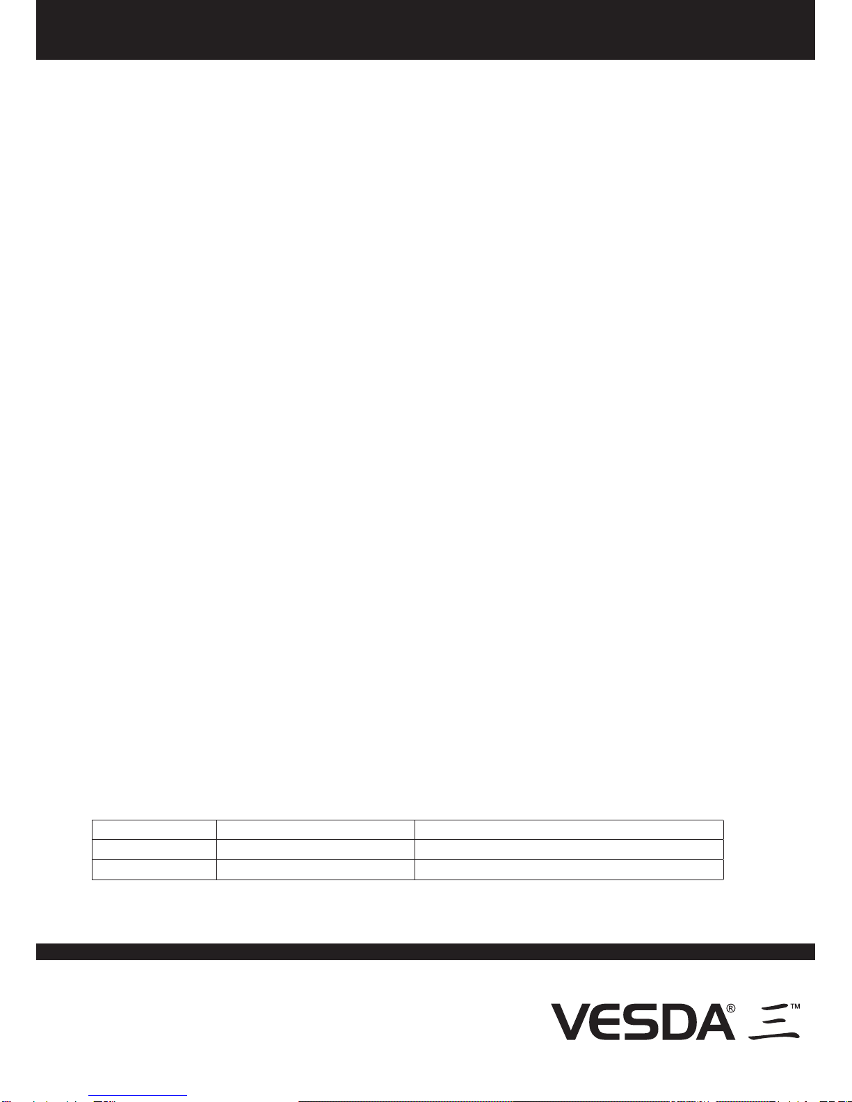
Diagnostic Table
Green LED RED LED Common Trouble (N.C. or N.O.)
ON - AC Present ON - DC Available Untripped - AC, DC and Battery OK
OFF - AC Fault OFF - DC Fault, Battery Fault Tripped - AC, DC and Battery Fault condition
Installation Instructions for
VESDA Power Supply Model VPS-VEA-115UL and VPS-VEA-230UL