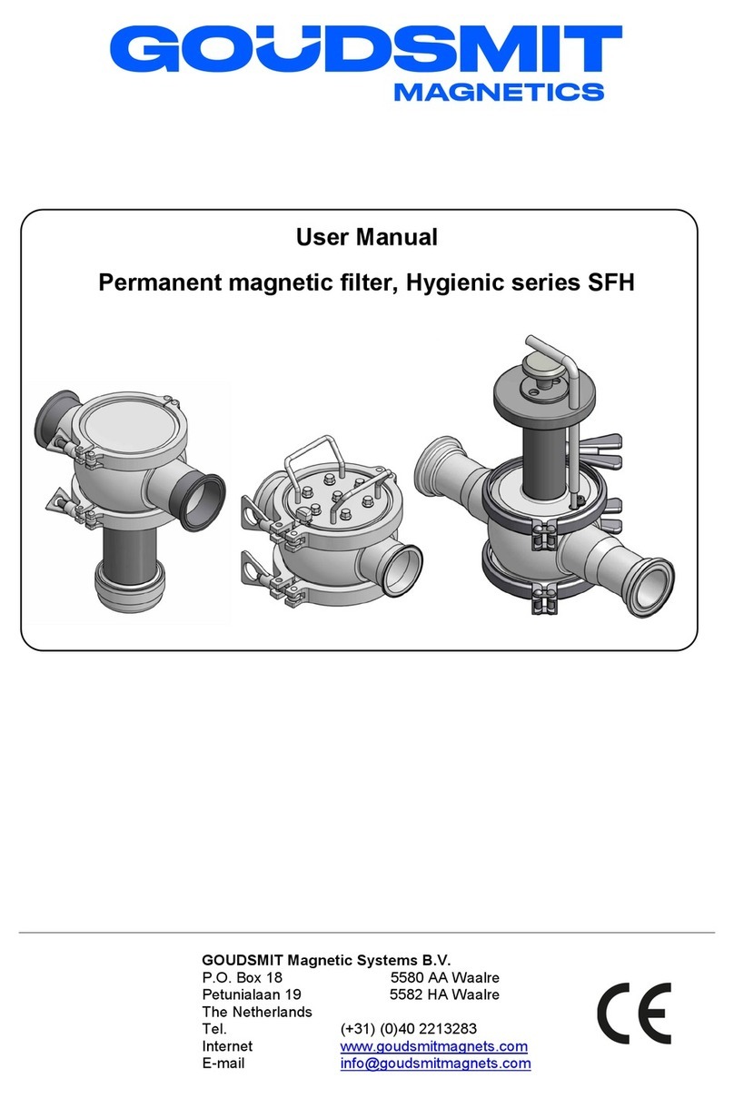
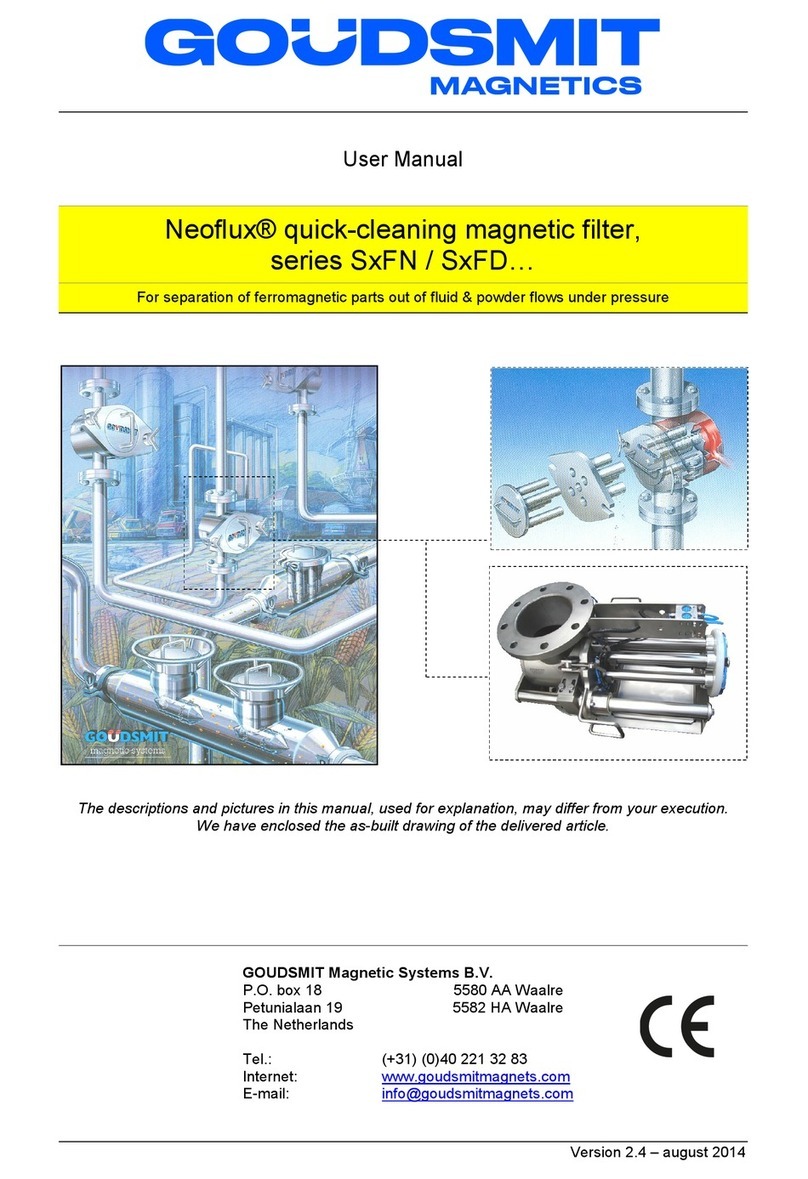
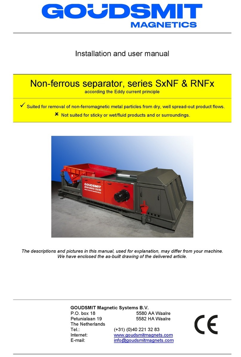
Goudsmit Neoflux SECR User manual

User Manual
Neoflux® Rotary Quick-cleaning Clean Flow Magnet,
SCR..SECR
Fe separator by permanent magnetic force
Suited for removal of ferromagnetic (like iron) parts out of powders and granulates
Not suited products that have a bad flowing capacity
The descriptions and pictures in this manual, used for explanation, may differ from your execution.
We have enclosed the as-built drawing of the delivered article.
GOUDSMIT Magnetic Systems B.V.
P.O. Box 18 5580 AA Waalre
Petunialaan 19 5582 HA Waalre
The Netherlands
Tel. (+31) (0)40 2213283
Internet www.goudsmitmagnets.com
E-mail info@goudsmitmagnets.com

Introduction
2
Introduction
Read this manual and make sure that you fully
understand its contents before commissioning and
operating the machine.
If you have any queries or require further explanation
regarding any subject related to the machine, please
do not hesitate to contact GOUDSMIT MAGNETIC
Systems B.V.
All technical information contained in this manual,
together with any relevant drawings and technical
descriptions we supply, remain our property. It may
not be duplicated or disclosed without our prior written
permission.
The user manual can be ordered together with the
device description and/or the article number as well as
the order number (ORxxxxxx).
This manual and the declaration by the manufacturer
are part of the machine.
They must remain with the machine, even if it is sold.
The manual must be made available to all operators,
service technicians, and others who work with the
machine throughout its life cycle.

List of contents
3
List of contents
Introduction...............................................................................................................................................................................2
List of contents .........................................................................................................................................................................3
General ......................................................................................................................................................................................4
Ferromagnetism ...................................................................................................................................................................4
Conditions of supply and guarantee......................................................................................................................................5
Delivery ................................................................................................................................................................................6
General ..........................................................................................................................................................................6
Identification plate...........................................................................................................................................................6
ATEX Markings (if applicable).........................................................................................................................................7
ATEX explosive zone measures .....................................................................................................................................8
Safety.........................................................................................................................................................................................9
General.................................................................................................................................................................................9
Danger of magnetic field .....................................................................................................................................................10
Danger of high voltage........................................................................................................................................................11
Danger of dust explosion ....................................................................................................................................................11
Device description ..................................................................................................................................................................12
Intended use / user indications ...........................................................................................................................................12
Deliverable specials............................................................................................................................................................13
Working principle ................................................................................................................................................................14
Standard Construction ........................................................................................................................................................15
Magnetic bar housings remarks ..........................................................................................................................................16
Installation...............................................................................................................................................................................17
Placing and transport procedures .......................................................................................................................................17
Gasket material / grounding................................................................................................................................................17
Electrical connections general ............................................................................................................................................18
Electrical motor installation (For Cleanflows without control box) ..................................................................................18
Connecting the control box ...........................................................................................................................................19
Electrical connections in control box .............................................................................................................................20
Electrical connections & EX..........................................................................................................................................20
Start-up....................................................................................................................................................................................21
Checks before and during start-up ......................................................................................................................................21
Maintenance ............................................................................................................................................................................22
Cleaning the rotor (Fe parts disposal) .................................................................................................................................22
Cleaning & ATEX................................................................................................................................................................22
Cleaning if rotor is mounted to housing.........................................................................................................................23
Cleaning rotor arm versions..........................................................................................................................................24
Motor reductor ....................................................................................................................................................................25
Malfunctions/Service ..............................................................................................................................................................26
Spare parts..............................................................................................................................................................................27

General
4
General
This user manual contains information for the correct operation and maintenance of your device. It also
contains instructions for avoiding possible injury and serious damage and it allows a safe and as
trouble-free functioning of the product as possible. Read this manual thoroughly before putting the
device into operation, familiarise yourself with the operation and control of the device and follow all
instructions precisely.
•The data published in this instruction manual is based on the available information at the time of
delivery. This is issued subject to later amendment.
•We retain the right to amend or modify the construction and/or model of our products at any time
whatsoever without any obligation to modify any previously supplied products accordingly.
Ferromagnetism
The working principle of the device rests on (Ferro)magnetism.
Ferromagnetism is the basic mechanism by which certain materials such as iron cobalt and nickel can
get magnetized when exposed to an externally applied magnetic field. Materials that remain magnetized
after the external magnetic field is removed, are called permanent magnets. Most magnetic materials
lose their magnetism after the external magnetic field is removed. Most alloys of iron, cobalt and nickel
are magnetic. However, some stainless steel alloys like AISI304 or AISI316 are only slightly magnetic.
Because in most cases it will be Fe parts that will be Ferro-magnetically influenced, we will use the term
‘Fe’ in this user manual when we mean ferromagnetic material

General
5
Conditions of supply and guarantee
The conditions of supply are the “General Conditions for the supply and erection of mechanical,
electrical and electronic products” (SE01), published by Orgalime, in Brussels.
These conditions can also- if desired – be requested by writing to Goudsmit Magnetic Systems B.V., as
also mentioned in our written quotation.
The guarantee prescriptions are mentioned in these conditions
The guarantee on your equipment will be void if:
˗Service and maintenance are not performed in accordance with the instruction manual or by
servicemen who are not especially trained to do the work. We strongly recommend that specific
magnetic service and maintenance be carried out by Goudsmit personnel).
˗Modifications are made to the equipment without our prior written permission.
˗Non-original parts or non 100% exchangeable parts are used.
˗Lubrication products other than those prescribed are used.
˗The equipment is used injudiciously, incorrectly, negligently or not in accordance with its intent
and/or purpose (see chapter “Intended use / user instructions”).
All parts that are subject to wear are excluded from the guarantee.
Remaining remarks / warnings
•Use the device only for the application for which it has been designed (see chapter “Intended use /
user instructions”).
•Use the device only when it is in technically perfect condition, and ensure that all protective hoods
or inspection covers, including all safety circuits, have been fitted and installed in the correct
manner.
•Ensure that device maintenance is appropriate and in accordance with the instructions provided in
this user manual.
•Any eventual faults, in particular those that may influence safety, should be attended to immediately
and remedied before renewed operation. Should you, after estimating the risks of an unsolved fault,
still think it is safe to keep the device into operation, then warn the operators and maintenance staff
of these faults and the danger(s) caused by these faults.

General
6
Delivery
General
Check the shipment immediately on delivery for:
˗Possible damage and/or shortcomings as a result of transport. If so, ask the transporter to draw up
a transport damage report.
˗Completeness of the delivery/deliveries, the absence of anything (additionally) ordered.
Always immediately contact GOUDSMIT magnetic systems in the event of any damage
and/or mistaken delivery.
Identification plate
On the device you will find an identification plate as pictured below. Information on this plate is of
great importance in case of service. That is why we advise to maintain this plate on the device at all
times. Ensure that it is always legible by cleaning regularly.
Product key:
Part no.:
Serial no.:
II 1/2D c T120°C Da/Db
0344
www.goudsmitmagnets.com
Weight:
Year:
Don’t forget to make note of the Serial number and Identification number in case of
breakdown(s) and or delivery of spare parts.
If your identification plate is damaged, contact us and we will send a new one as soon as possible.
Product key
Identification
number
Device weight [kg]
Year of production
ID-number
Notified body
Example ATEX code
(if ordered)
Serial number

General
7
ATEX Markings (if applicable)
When the equipment is suitable for use in potentially explosive atmospheres (ATEX) the type plate will
feature an Ex Marking specifying the specific device category and other criteria that the equipment
satisfies.
•Code example: II 1/2D c T120°C Da/Db
•Explanation:
II explosion group (I is underground mining, II is other)
1/2D Equipment Category (Ignition protection level: 1 = very high, 2 = high, 3 = normal)
1D inside device / 2D outside device
c Type of Ex protection
c = constructional safety
t = protection by enclosure
h = non-electrical equipment (protection method not specified further)
T120°C Maximum surface temperature
Da/Db Equipment Protection Level (EPL).
EPL
Da
Db
Dc
Suited for ATEX zone(s)
20 (21, & 22)
21 (22)
22
Da inside device / Db outside device
Ta Ambient temperature range; only displayed when the range deviates from the standard
temperature range for ATEX of -20 … +40°C
If the device is externally certified, then the ATEX certificate number is added to the type plate. Next to
the CE mark the identification number of the Notified Body that certified our ATEX quality assurance
system is displayed.
In case the equipment contains no ‘own ignition sources’ and therefore is not under scope of the ATEX
Directive, then the equipment will not get an EX marking and wil be supplied with a Statement of
Exclusion, in which this is stated and also the EX zones are listed in which it can be safely used.
Equipment category
1D
2D
3D
Suited for ATEX zone(s)
20 (21, & 22)
21 (22)
22

General
8
ATEX explosive zone measures
•If the device has been ordered for use in a potentially explosive area, make sure that no higher
surface temperature arises then permitted by ATEX.
The ATEX marking on the Goudsmit identification plate only applies to the product produced by
Goudsmit Magnetic Systems B.V.
•The ATEX certified magnetic device requires additional purchase parts to be certified to the ATEX
Directive. This includes control units, connection box(es), switch(es), sensor(s) and pneumatic
parts, etc. Make sure that these are fitted by qualified personnel!
•If the device is placed in storage or has a longer standstill, make sure the device is emptied and
cleaned.
•The device must be grounded, if a gasket is used between the device and the larger installation.
Attach a metal strip between the housing of the device and the installation, to make sure the device
is grounded.
•All screw connections inside the device must be secured against loosening.
The ATEX purchase parts are provided with their own ATEX markings.
Make sure no particles > 10 mm are present in the product flow.
These can damage the magnet or extractor bars or cause impact sparks.
If necessary install a mechanical filter (sieve) before the separating equipment!

Safety
9
Safety
Regularly check that all warning pictograms are still present and legible, and clean if necessary.
Make sure that new pictograms are applied at their correct locations if they have been lost or
damaged.
General
The device is provided with safeguards where necessary. Make sure every person who comes in contact
with the device, wears adequate personal protection (overalls, safety glasses, hearing protectors, helmet,
steel-toed safety shoes etc.).
Areas of the device considered dangerous are marked with warning pictograms.
If the device remains easily accessible to persons, then extra safety precautions (e.g. fencing) must be
installed. When safeguards are not possible, make sure clear instructions are given to people using the
device.

Safety
10
Danger of magnetic field
The magnets generate a powerful magnetic field that strongly attracts ferromagnetic (Fe) materials.
Always take into account that these materials may suddenly be drawn towards the magnet, very
powerfully. This applies to steel workbenches and steel tools, but also to Ferromagnetic materials
carried on your person, such as coins in your wallet or your keys. Make use of non-magnetic tools and
workbenches fitted with a wooden worktop and preferably a non-Fe frame (for instance stainless steel).
Always be aware that Ferromagnetic parts will be attracted -- even personal items - if you are
closer than 0.3 meter to a magnet.
Danger - strong magnetic field!
People fitted with pacemakers should on no account enter the magnetic field
(within a radius of 1 meter).
Prohibited for people with pacemakers!
Credit cards, chip cards, computer disks/tapes, computer screens, watches,
etc. may be damaged or destroyed if they enter the magnetic field (within a radius of 0.5 meter).
Danger for magnetic cards!
!
!
!

Safety
11
Danger of high voltage
When installing and electrically connecting the device, make sure the activities are performed by qualified
personnel.
Switch off the electrical power supply before performing activities to the device!
Danger – Risk of an electric shock!
Always use the main power switch (on the control box) to switch off the installation in the event of a
dangerous situation.
Do not restore power until the dangerous situation has been resolved!
Danger of dust explosion
If this device is made according to an EX dust category (1D/2D/3D, acc. to ATEX equipment directive
2014/34/EU) it can accordingly be used in a dust zone (20/21/22, acc. to ATEX workplace Directive
99/92/EC). The Ex category is then described on the identification plate.
Make sure that the device complies to the correct explosion category.
Danger – dust explosion!
(no sticker on device)
Also check if the identification plates of mounted parts show the correct Ex-category for the Ex
zone in which the device will be used.
!
!

Device description
12
Device description
Intended use / user indications
Product
The device is suited for separation of ferromagnetic (Fe) parts out of free flowing powder and granular
products, grain size up to 10 mm, such as flour, sugar, coffee beans, plastics, ceramics, etc.
Not suited for (moist) products that are sticky and/or badly flowing.
Fe particle size
Suited for product flows with Fe particles of 30 µm and larger, depending on magnet strength quality.
See product specs in the appendices for exact Fe parts size specification.
Product should be free of Fe part size and weight that can cause damage to the magnet bar tubes.
Mechanical or other sieving of larger parts is advised.
Foreign part size
Foreign part (like other metals) size that can cause damage to the magnet bar tubes have to be filtered
out.
Mechanical or other sieving is advised.
Temperature
Suited for surrounding temperatures from -20 °C up to +40 °C and product temperatures from -20 °C up
to +60 °C with standard Neoflux® magnets.
See product specifications in the appendices for max. product temperature.
The magnet is to be protected against higher temperatures than prescribed, because the magnet might
lose magnetic force permanently when exposed to high temperatures
Air pressure
The relative pressure inside the device must be under 0.2 barG. The relative vacuum inside the device
must be under -0.5 barG.
If an air pressure coupling is mounted on the flange, it may be redundant if the product channel has an
overpressure. Also, it may not function if there is a relative vacuum in the product channel.
Air pressure between seals on motor shaft and housing
An air pressure seal may be mounted between the motor and Cleanflow housing. This is to prevent any
oil or debris from the motor reductor from entering the product channel. If an air coupling is mounted to
the motor mounting flange, then the maximum supply pressure is 0.1 barG. This pressure may only be
connected if an air coupling is mounted. If a closing plug is fitted, then the system is not suitable for
applying an overpressure. The air coupling will only work optimally if the air pressure is equal between
the outside and inside of the product chute.
Free space
Make sure that there is approximately 1 meter of free space around the SECR to perform and ease the
inspection and maintenance operation.

Device description
13
Noise level
The noise level generated by the device is significantly below 70 dB(A).
Vibrations
The magnet is to be protected against strong external vibrations, because the magnet might lose
magnetic force permanently and or the brittle ceramic magnet material might break.
The only vibrations caused by the SECR are caused by the moving and rotating magnet bars. The
product channel in which the device is mounted has to be stiff enough to damp out the (relatively small)
forces of the moving and rotating magnet bars.
Cleaning
Minimum 2x per day cleaning (Fe parts disposal) of the device is advised for an optimal magnetic
separation and to prevent Fe accumulation on the magnet bar tubes and the problems that can be
caused by that. Clean more often when the magnets catch a lot of Fe parts and less often if proven that
2x per day is too much. Clean magnets have the best separation result, so make sure to clean more
often than assumed necessary, to achieve a satisfactory result of the magnetic device.
Deliverable specials
High product temperatures
For high product temperatures there is the possibility of using other magnet material than the standard
Neoflux® magnets. See product specs in the appendices.
Abrasive products
If you have an abrasive product, we can supply the magnet bars and /or inside housing with a protective
coating, like for instance a tungsten carbide coating.
Use in FOOD product flows
The cleanflow magnet can be adapted so that it can be used in almost any food stream. It’s standard
execution already has few gaps in the product channel. The product channel (or even complete housing
+ magnet bars) can be delivered in gap-free SS AISI304 or AISI316, or in combination with other – for
instance prescribed or delivered by customer – food appproved materials. Surface treatments like
electrolytic polishing, staining, etc, are also possible.

Device description
14
Working principle
•The rotating clean flow magnet is suited for separation of ferromagnetic (Fe) particles out of product
flows.
•By rotation of the magnet bars on a rotor, bridge forming on the bars is relatively little and thus a
much better Fe separation result is created.
•For becoming a high quality de-ironing processes, clean flow magnets have a very high magnetic
field value on the magnet bars. The “sticking” strength of the magnets and the speed of the rotor can
be differently designed, varied with the flow rate, type of product and magnet selection.
Figures: Basics of Fe separation process Cleaning by pulling out rotor and extractor
•The product, contaminated with Fe parts, passes one or more magnet bars while flowing through
the rotating clean flow magnet.
•The Fe parts will be ‘sucked’ towards a magnet bar and will cling onto it.
•The Fe parts will stay on the bar until the magnet bars will be cleaned of the Fe parts
Before a cleaning action the product flow needs to be temporarily interrupted.
•Cleaning the magnet bars of the Fe parts is very easy; the magnets can be simply pulled out of the
surrounding stainless steel tubes. When this is done the Fe parts will instantly fall off the tubes and
can then be caught and/or transported.
Product IN
Product OUT

Device description
15
Standard Construction
1. The actual magnet unit is the rotor, consisting of an extractor and several very strong Neoflux®
magnet bars.
2. The extractor consists of 2 flanges with tubes welded or soldered in-between.
3. The magnet bars are mounted on one side to a flange and form the magnetic part of the rotor
assembly, it fits exactly into the extractor part of the rotor.
4. The flanged motor is bolted to the SS housing.
5. The housing has an inlet and an outlet flange with holes for bolted mounting.
6. The rotor can be taken out of the housing for cleaning or inspection, by opening the door, which is
held tightly closed by 2 fastener clamps.
7. Some SECR types have an extended motor shaft and an extra bush between housing and motor to
help to discover oil loss through the shaft more easily and so further reduce the danger of motor oil
penetrating into the product canal.
8. The control box is connected to the safety latch switch unit; if the door is opened during production,
the motor will shut off. The safety latch is locked into the latch safety switch unit.
9. The silicone seal at the door prevents leakage of product out and dirt into the device.
Safety latch
switch unit
Silicone seal
Control box
Flange
Magnet
Flange
Motor
Extractor
Door
with
Fastener

Device description
16
Magnetic bar housings remarks
•The cleanflow has fragile magnetic bar housings. The housings have a very small wall thickness,
which ensures maximum déferrisation.
Heavy contamination of the product flow can damage the housings.
•Make sure that heavy or non-magnetic parts are filtered out of the product flow before it passes the
cleanflow magnet! Place a sieve in the product stream before it reaches the cleanflow!
•During maintenance or cleaning be very careful with the magnetic bar housings.
Always place the magnet section with the ends down and the flange up, not on its side.
•When the magnetic bars are damaged it may be difficult to move the bars in their housings; If this
occurs it is advised to replace the tubes or let the tubes be replaced by Goudsmit, to avoid further
damage.
•Damage to the magnet bar tubes and damage caused by damaged magnet bar tubes is not covered
by the guarantee. Please take the utmost care when cleaning the device!

Installation
17
Installation
Placing and transport procedures
The rotating clean-is always to be lifted by 4 lifting lugs!
Keep the centre of gravity into consideration. This is not in the middle of the device, but closer to the
motor side.
•Use proper lifting devices that suit with device’s weight. Clear the area under the magnet during
transport.
Read the weight of the clean flow magnet on the identification plate.
•The device is delivered in a wooden box. Bolt a lifting lug to each of the 4 corners of the magnet
housing flange for stable transport process. Keep each corner on the same level for proper
alignment before installation.
•Close the door and quick locking mechanisms properly to prevent the extractor and magnets of
falling out of the housing. Check that the rotor (extractor and magnets) is clamped tidily to the shaft.
•Bolt the flanges of the device tidily to the inlet and outlet flange of your product canal. Improper
alignment and loose assembly may cause leakage of raw product. Ensure that the channels are
strong enough to support the weight of the clean flow magnet and raw product in it.
•It is best to install the clean flow magnet in a well reachable height to the operators. A good height
eases the cleaning process.
•Avoid any impact during transport to prevent damage, especially to the rotor. Damage to the
extractor can cause magnets to “stick” into the extractor.
•To prevent physical damage and abrasion the cabling on the outside of the device requires
adequate protection.
Gasket material / grounding
To prevent the build-up of static electricity, make sure there is metal bridge between the magnetic
device / product channel and the installation. The completed installation must also be grounded.

Installation
18
Electrical connections general
Make sure that the electrical power supply is switched off while you work on the device.
Make sure that all electrical connections are made by qualified personnel and conform to all the applicable
standards. Check that the device is suitable for connection.
Check all connections regularly!
The electrical supply voltages of the motor are indicated on the type plate of the motor.
Electrical motor installation (For Cleanflows without control box)
Check that the rotation is correct:
Briefly switch the motor ON.
If incorrect, reverse 2 phases (U - V):
(It makes no difference whether you have a Υor a Δcircuit!)
Also remember to connect the Earth wire!

Installation
19
Connecting the control box
The electrical supply voltages of the (optional) control box can be found in the connection diagrams
attached in the documentation.
Device with control box in delivery:
Review the connection diagrams thoroughly and / or connect your voltage to the clamps L1, L2, L3 and
earth of the control box.
No control box in delivery:
Then no connection schematics will be delivered with the product. Connect to the control used at the
site control and / or consult a professional installation technician.
Photo: Connecting supply voltages
Standard terminal box
L1
L2
L3
PE

Installation
20
Electrical connections in control box
Connect the electric parts in the switch box preferably according to the schematics included in the
delivery
Check the electrical connection is correct by executing the following procedure, after switching on the
mains supply.
1. open the door of the cleanflow motor should not react.
2. close the door, start cleanflow motor should start.
Photo: standard terminal box
Electrical connections & EX
If the device is placed in an Ex zone, everything you add or change to the device's electrical installation
must be executed and documented according to the regulations for the specific Ex zone.
This manual suits for next models
1
Table of contents
Other Goudsmit Water Filtration System manuals
Popular Water Filtration System manuals by other brands

GE
GE GXRM10RBL Dimensions and installation information

BWT
BWT MINISTIL 1iD Installation and operating manual

BLUE COLLECTION
BLUE COLLECTION KIVI quick start guide

Monarch Water
Monarch Water WELLBEING GEMINI install guide

Watts
Watts PWFGAC1 Installation, operation and maintanance manual

BWT
BWT Infinity A Installation and operating manual

Ken Pure
Ken Pure Classic user manual

AQUAPHOR
AQUAPHOR J. SHMIDT 500 instruction manual

United Industries
United Industries TOWER-FLO TFW Series Technical manual

DAYLIFF
DAYLIFF Poolchlo30 Installation & operating manual

Waterway
Waterway CLEARWATER II user manual

Ecosoft
Ecosoft RO 5-36 Installer and user guide