XtremepowerUS 62FT User manual

ATTENTION INSTALLER: THIS MANUAL CONTAINS IMPORTANT INFORMATION ON THE
OPERATION, AND SAFE USE OF THIS EQUIPMENT.
THIS MANUAL IS INTENDED FOR THE END USER OF THIS PRODUCT
MODEL EFFECTIVE FILTRATION RATE DESIGN FLOWRATE
Residential Commercial
FT2 M2GPM LPM
71204
44663
MAXIMUM WORKING PRESSURE FOR ALL MODELS 50 PSI (3.45 BAR)
DE FILTER 62FT / 48FT
ITEM:75205 / 75206
75205
75206

This is the safety-alert symbol. When you see this symbol on your equipment or in this manual, look for one
of the following signal words and be alert to the potential for personal injury or death.
WARNING Warns about hazards that could cause serious personal injury or, death, and or major property
damage and if ignored presents a potential hazard.
CAUTION Warns about hazards that will or can cause minor or moderate personal injury and/or property
damage and if ignored presents a potential hazard. It can also make consumers aware of actions that are
unpredictable and unsafe.
The NOTICE label indicates special instructions that are important but not related to hazards.
READ, UNDERSTAND, AND FOLLOW ALL SAFETY AND OPERATION INSTRUCTIONS.
FAILURE TO FOLLOW SAFETY AND OPERATION INSTRUCTIONS CAN RESULT IN SEVERE
PERSONAL INJURY OR DEATH.
CAUTION To reduce risk of injury, do not permit children to use or climb on this product. Closely
supervise children at all times. The ANSI/NSPI-4 Standard (above-ground and on-ground pools)
their being used as a means of access to the pool by young children.
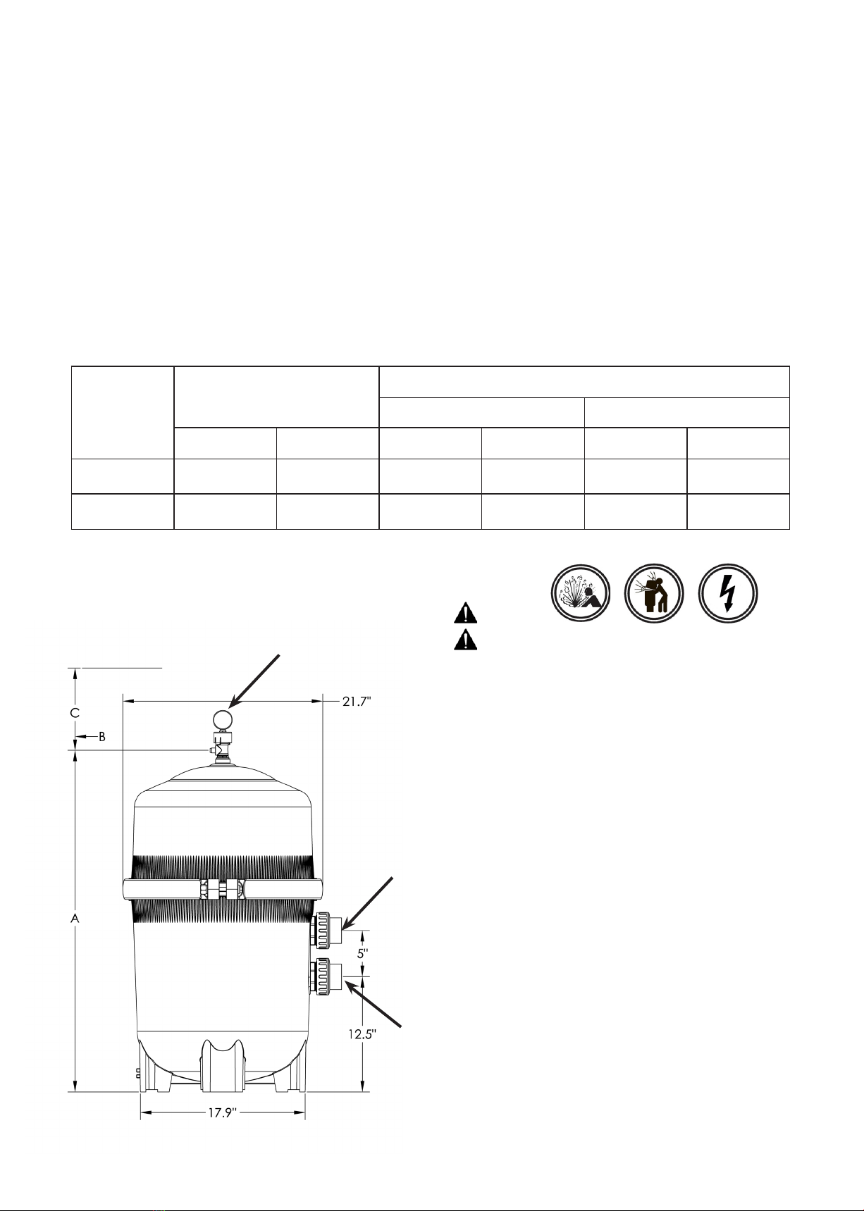
WARNING COMPONENT SEPARATION HAZARD
Pool and spa water circulation systems operate under hazardous pressure during start up, normal
operation, and possibly after pump shut off. Pressure in system can cause explosive component
injury or death can result.
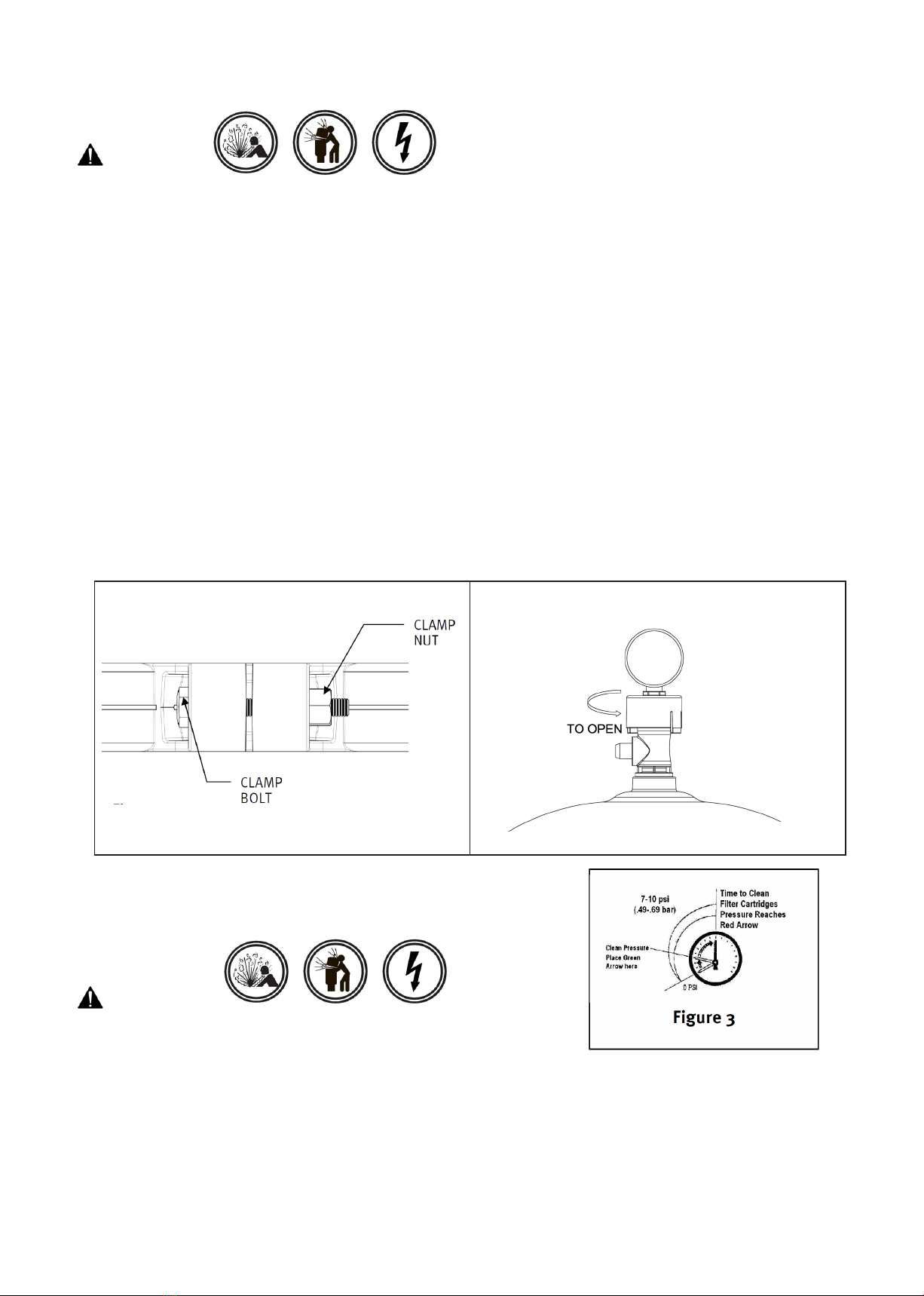
TO AVOID COMPONENT SEPARATION
missing, or not a genuine component.
cause explosive separation.
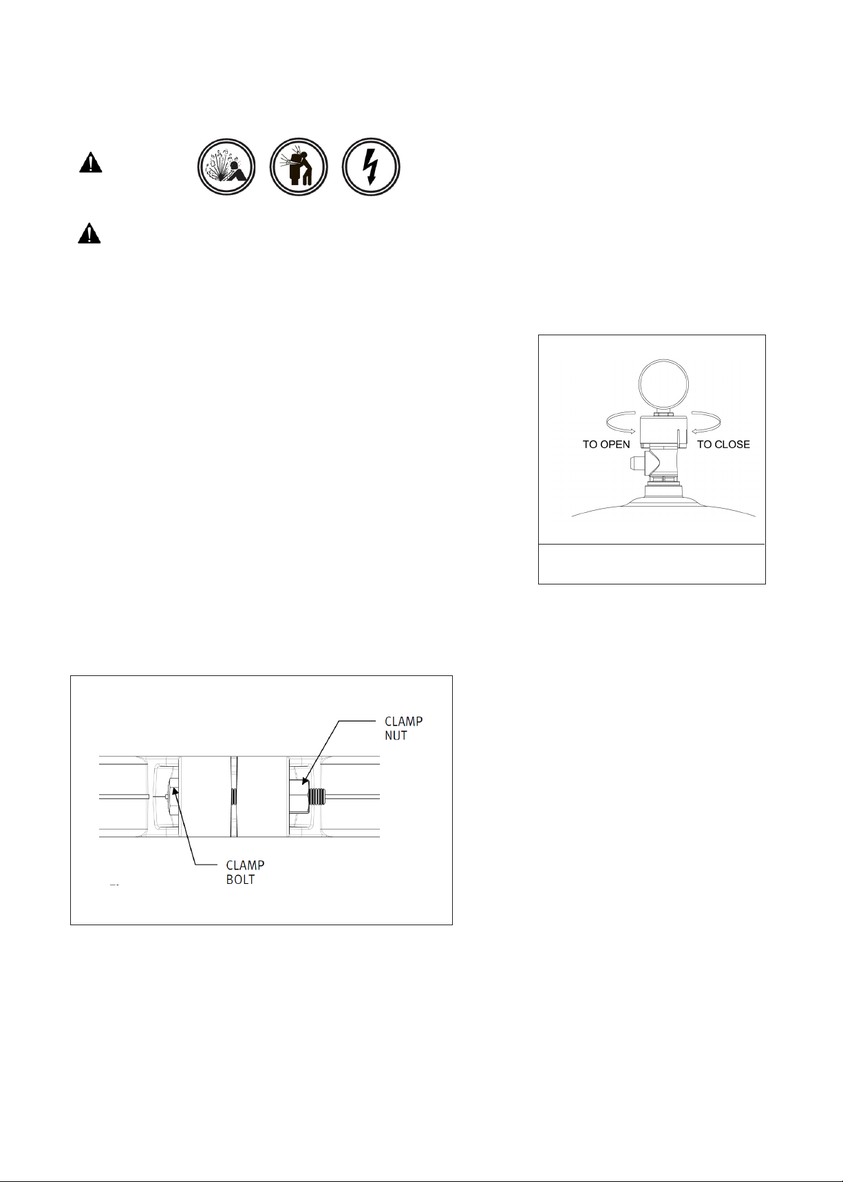
torque clamp nut and clamp bolt to 150 inch-lbs.
upper body.
the clamp system per the instructions in this owner’s manual to stop the leak.
water mix) is discharged from the manual air relief valve.
WARNING EXCESS PRESSURE HAZARD
of the components. Component separation can result in severe personal injury or death.

WARNING ELECTROCUTION HAZARD
High Voltage electricity is present in the pool and spa equipment. High voltage electricity can cause
shock and electrocution. Shock and electrocution can result in severe personal injury or death.
National Electrical Code (NEC).
bonding requirements.
WARNING – SUCTION ENTRAPMENT HAZARD.
Suction in suction outlets and/or suction outlet covers that are, damaged, broken, cracked, missing, or
unsecured can cause severe injury and/or death due to the following entrapment hazards:
Hair Entrapment- Hair can become entangled in suction outlet cover.
Limb Entrapment- A limb inserted into an opening of a suction outlet sump or suction outlet cover that
is damaged, broken, cracked, missing, or not securely attached can result in a mechanical bind or
swelling of the limb.
Body Suction Entrapment- A negative pressure applied to a large portion of the body or limbs can
result in an entrapment.
Evisceration/ Disembowelment Entrapment- A negative pressure applied directly to the intestines
through an unprotected suction outlet sump or suction outlet cover that is, damaged, broken, cracked,
missing, or unsecured can result in evisceration/ disembowelment entrapment.
knuckle to be caught in an opening of a suction outlet cover resulting in mechanical entrapment.
TO REDUCE THE RISK OF ENTRAPMENT HAZARDS:
from near point to near point.
user.
missing, or not securely attached.
components.
material can result in an increased potential for suction entrapment.
SAVE THESE INSTRUCTIONS

GENERAL INFORMATION
Vertical Grid D.E. Filter combines superior water filtration with ease of operation and totally corrosion-free
construction. It uses diatomaceous earth (D.E.), which is the most efficient dirt remover and filter medium known.
The D.E., which is usually fed through the skimmer at initial start-up, uniformly coats the filter elements that are
covered with a custom fitted monofilament polypropylene filter cloth. As pool water is pumped through the control
valve into the bottom of the filter tank, the D.E. surface, or coating, filters out even the minutest particles resulting in
clear, clean, sparkling water.
After a period of time, the accumulated dirt in the filter causes a resistance to flow, the pressure rises, and flow
diminishes. This means the dirt holding capacity of the D.E. has been reached, and it is time to clean (backwash)
your filter. With the control valve in the back wash position, the water is automatically reversed through the filter,
flushing trapped dirt, debris and D.E. out the waste line. Once the filter is backwashed (cleaned) of D.E. and dirt,
the control valve is manually re-sequenced to filter position and a fresh charge of D.E. is added to resume normal
filtering.
AREQUIRED CLEARANCE
"B" SIDE "C"ABOVE
IN CM IN CM IN CM
37 94 18 46 14
44.3 112.5 18 46 22 56
INSTALLATION
WARNING
This product should be installed and
professional.
1.The filter system should be installed on a level concrete
slab or other rigid base. Select a well drained and vented
area, one that
connections, and
winter drain are convenient and accessible for operation,
service, maintenance and winterizing.
by gravity.
3 the shade to shield
it from continuous, direct heat from the sun.
4.Assemble appropriate Filter Control valve (not
included) to filter. Lubricate the O-ring first . Align the
two (2) valve pipe connections, with O-rings in place, with
the two openings in the side of the filter tank and press in
firmly. Secure the assembly to the tank connections with
the two bulkhead lock nuts. Do not over-tighten.
5. Connect the pool suction plumbing between the
skimmer, pool outlet and the pump.
9. Verify water discharge from the manual air relief
valve(MAR) is directed away from electrical devices.
Manual Air Relief
OUTLET
INLET
75205
75206

OPERATION
WARNING
FILTERING
Filtration starts as soon as the filter has been pre-coated. As the filter removes dirt from the pool water, the
accumulated dirt causes a resistance to flow. As a result, the gauge pressure will rise and the flow will decrease.
When the pressure rises 8-10 psi (.55-.69 bar) above the pre-coat pressure, it is time to backwash (clean) the
filter. Once your filter is running and there is a pressure reading, line up the green arrow with the current reading.
(See Fig 3) When the pressure rises to or above the red or second arrow, it is time to clean your filter.
Note: During initial clean-up of the pool, particularly with a new pool or a very dirty pool, it may be necessary to
backwash more frequently due to the heavy initial dirt load in the water.
STARTING THE PUMP and FILTER SYSTEM
WARNING
Before Starting the Pump
1. Use ONLY Original components; Non-Original clamp components may fail in use and cause explosive
components.
(See Fig 2)
the pool.
4. Place the manual air relief valve in OPEN position. (See Fig 2)
Starting Pump
water leakage has stopped.
Reassemble the clamp system per the instructions on page 7 in this owner’s manual to stop leak.
mix) is discharged from the manual air relief valve.
Figure 2
Manual Air Relief shown open
Figure 1

FILTER CONTROL VALVE FUNCTIONS
Six-Way Filter Control Valve
FILTER–
BACKWASH–
a. Shut off the pump.
b. Set Filter Control Valve to BACKWASH.
c. Start Pump and backwash approximately two minutes,
or until water out waste line appears clean.
d. Shut off pump.
e. Set Control Valve to RINSE.
f. Start pump and operate for 20 seconds.
g. Shut off pump.
h. Set Filter control valve to FILTER.
i. Proceed as in Pre-Coating to add fresh D.E.
Four-Way Filter Control Valve
FILTER–
WASTE–
BACKWASH–
POOL OR SPA BOOST
Two-Way Slide Valve
FILTER–
BACKWASH–
BACKWASH
FILTER
Pre-Coating
O-RING
RETAINER NUT
WASHER
MANIFOLD
BOLT
LOWER BODY SEALSURFACE
DRAIN PLUG WITH O-RING
Figure 4
RINSE–
WASTE
RECIRCULATE–
CLOSED–

MAINTAINING YOUR FILTER
WARNING
This product should be installed and serviced only by
FILTER DISASSEMBLY INSTRUCTIONS
1. Turn off all system circulation pumps and all electric
power on the equipment pad.
3. The manual air relief valve must be placed in the OPEN position. (Fig 6)
and the clamp bolt. (Fig 5)
clamp during removal, because the clamp could be damaged. Do not
strike the clamp with metal tools as they can damage the clamp.
Figure 6
Manual Air Relief shown open
REMOVING ELEMENT CLUSTER
1. Remove the
using slight rocking motion and lifting up.
CLEANING FILTER ELEMENT CLUSTER
cluster,
wash
Figure 5

FILTER RE-ASSEMBLY INSTRUCTIONS
WARNING
RE-INSTALLING
1. Lubricate outlet elbow O-rings
Replace filter element cluster into filter tank, carefully
fitting top collector manifold outlet over outlet elbow O-ring.
CLEAN SEAL RING AND SEAL SURFACE
clean seal of all dirt and debris. (Fig 4) Do not use a solvent.
components.
WARNING
This product should be installed and serviced only by a
BODY AND CLAMP RE-ASSEMBLY
1. Place the metal reinforced seal on lower
body in a position which allows all
operation and safety labels to be clearly
body to seat the seal. (Fig 7)
3. Insert clamp bolt through the clamp ends and thread the clamp nut onto clamp bolt with rounded end of the
nut (Fig 8) towards the ends of the clamp.
clamp nut to clamp bolt to 150 inch-lbs. (Fig 9)
DO NOT HIT OR STRIKE CLAMP WITH HAMMER OR METAL TOOLS.
VACUUMING POOL
Backwash filter after vacuuming, if required.
DRAIN
PLUG LOWER
FILTER
BODY
ALIGN
LABELS
Figure 7
Clamp bolt
Rounded end of nut
Figure 8
using a
Figure 9

REMOVING THE MANUAL AIR RELIEF VALVE
WARNING
This product should be installed and serviced only
Your Filter comes with a Manual Air Relief Valve (MAR)
preinstalled rom the factory.
to be serviced, follow these instructions carefully.
1. Turn off all system circulation pumps and all electric
power on the equipment pad.
2. Set all system valves in a position to prevent water
3. The manual air relief valve must be placed in the OPEN
position.
4. Wait until all water leakage has stopped.
5. The air relief valve can be removed by screwing the
whole parts counter clockwise.
RE-INSTALLATION OF THE MANUAL AIR RELIEF VALVE
1. Check the o-ring seals, replace as needed.
6. Verify the MAR discharge points away from all electrical connections.
WINTERIZING FILTER
WARNING
from damage.
2. Follow directions under FILTER DISASSEMBLY INSTRUCTIONS
3. Then follow REMOVING per instructions
4. Reassemble per FILTER RE-ASSEMBLY INSTRUCTIONS.
Figure 10

SERVICE AND REPAIRS
SUGGESTED POOL CHEMISTRY LEVELS
H 7.2 to 7.8
TOTAL ALKALINITY 80 to 120 ppm
CALCIUM HARDNESS 200 to 400 ppm
COMBINED CHLORINE .2 ppm Maximum
CHLORINE (STABILIZED) 1.0 to 3.0 ppm
CHLORINE STABILIZER
(Cyanuric Acid) 60 to 80 ppm
PROBLEM SOLVING LIST
REMEDY
LOW WATER FLOW SHORT FILTER CYCLES POOL WATER WON’T CLEAR UP
1. Check
andpump strainer
baskets or debris.
2. Check for restrictions
in intake and discharge
lines.
3. Check for air leak in
intake line (indicated by
bubbles returning to
pool).
4.Backwash (Clean)
Filter
1. Check for algae
in pool and super-
chlorinate as required.
2. Be sure chlorine
and pH levels are in
proper range (adjust as
required).
1. Check chlorine, pH and total
alkalinity levels and adjust as
required.
0
5
10
15
20
25
025 50 100 125 150
Head loss in Feet of Water
75
Flow Rate in GPM
Head Loss

No. Part No. Description QTY
1 5024015000 Pressure Gauge 1
2 647311973000 Manual Air Relief Assembly 1
3a 47311901080 Upper Filter Body(small) 1
3b 47311905080 Upper Filter Body(large) 1
4 647311971000 Clamp System 1
5 5431146080 O-Ring 1
6 5758083000 Air Relief Filter 1
7 5431073080 O-Ring 1
8 47311913001 Adaptor 1
9a 5748122001 PVC Pipe (short) 1
9b 5748123001 PVC Pipe (long) 1
10 47311908001 Adaptor(short) 1
11 47311909001 Adaptor(long) 1
12a Filter Element cluster
(H=608mm) 1
12b Filter Element cluster
(H=792mm) 1
13 47312507080 Filter Element Locator 1
14 47311902080 Lower Filter Body 1
15 47312508080 Adaptor plug screw 2
16 5471147080 O-Ring 2
17 Retainer nut 1
18 5244060000Seal 2
19 47312512001 Top Collector Manifold 1
20b Long Bolt 1
21 91215001 1 1/2 Drain Plug w/O-Ring 1
5233042000
5227066000
20a Short Bolt 1
5227065000
647312572
647312571
a-20b

OF NOTE
THE MANUFACTURER AND/OR DISTRIBUTOR HAS PROVIDED THE PARTS LIST AND ASSEMBLY
DIAGRAM IN THIS MANUAL AS A REFERENCE TOOL ONLY. NEITHER THE MANUFACTURER OR
DISTRIBUTOR MAKES ANY REPRESENTATION OR WARRANTY OF ANY KIND TO THE BUYER THAT
HE OR SHE IS QUALIFIED TO MAKE ANY REPAIRS TO THE PRODUCT, OR THAT HE OR SHE IS
QUALIFIED TO REPLACE ANY PARTS OF THE PRODUCT. IN FACT, THE MANUFACTURER AND/OR
DISTRIBUTOR EXPRESSLY STATES THAT ALL REPAIRS AND PARTS REPLACEMENTS SHOULD BE
UNDERTAKEN BY CERTIFIED AND LICENSED TECHNICIANS, AND NOT BY THE BUYER. THE BUYER
ASSUMES ALL RISK AND LIABILITY ARISING OUT OF HIS OR HER REPAIRS TO THE ORIGINAL
PRODUCT OR REPLACEMENT PARTS THERETO, OR ARISING OUT OF HIS OR HER INSTALLATION
OF REPLACEMENT PARTS THERETO.
Record Product’s Serial Number Here:
Note: If product has no serial number, record month and year of purchase instead.
Note: Some parts are listed and shown for illustration purposes only and are not available individually
as replacement parts.
PLEASE READ THE FOLLOWING CAREFULLY
PRODUCT MADE IN CHINA
This manual suits for next models
3
Table of contents
Other XtremepowerUS Water Filtration System manuals
Popular Water Filtration System manuals by other brands

Flexco
Flexco Novitool Ply 130 Safety and operation manual

Berkey
Berkey PF-2 manual

Trox
Trox TFP-TC-S Installation and maintenance manual

APEC
APEC ULTRA REVERSE OSMOSIS SYSTEM Installation instructions and owner's manual

Allfyll
Allfyll Series N instruction manual

First Water
First Water FW-1200-M Operation manual