XVTEC XVC-ULTRA User manual

XVC-ULTRA Encoder
User’s Guide
V5

XVC-ULTRA Encoder User’s Guide
Page 2 of 50
XVTEC LTD.
24 Ha'nagar Street
Hod Hasharon
Israel
Telephone: +972-79-3002300
Email: info@xvtec.com
Web: https://www.xvtec.com
The information contained in this document, or any addendum or revision thereof is proprietary of XVTEC Ltd. and is subject to all relevant
copyright, patent and other laws and treaties protecting intellectual property, as well as any specific agreement protecting XVTEC Ltd.
rights in the aforesaid information. Any use of this document or the information contained herein for any purposes other than those for
which it was disclosed is strictly forbidden.
XVTEC Ltd. reserves the right, without prior notice or liability, to make changes in product design or specifications.
XVTEC Ltd. assumes no responsibility for the use thereof nor for the rights of third parties, which may be affected in any way by the use
thereof.
This document may contain flaws, omissions or typesetting errors; no warranty is granted, nor liability assumed in relation thereto unless
specifically undertaken in XVTEC Ltd.’s sales contract or order confirmation.
Information contained herein is periodically updated and changes will be incorporated into subsequent editions. If you have encountered
an error, please notify XVTEC Ltd.
All specifications are subject to change without prior notice.
© Copyright by XVTEC Ltd., 2019. All rights reserved worldwide.

XVC-ULTRA Encoder User’s Guide
Page 3 of 50
Table of Contents
INTRODUCTION .......................................................................................................................................7
Key Features.......................................................................................................................................... 7
Testing environment ............................................................................................................................. 7
Additional Support ................................................................................................................................ 7
Definitions ............................................................................................................................................. 8
GETTING STARTED ...................................................................................................................................9
Unpacking the Encoder Hardware ........................................................................................................ 9
Installing the XVC Management Tool.................................................................................................... 9
USING THE ENCODER HARDWARE ......................................................................................................... 10
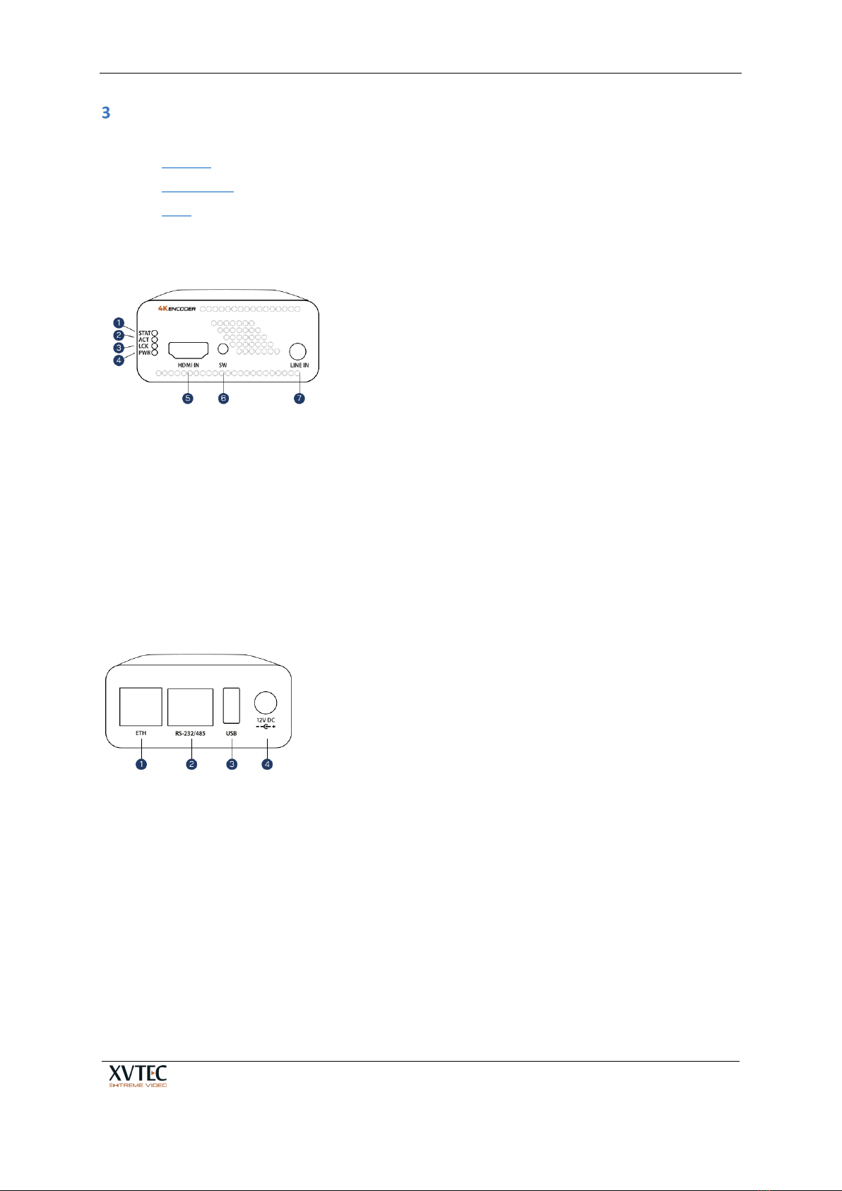
Buttons................................................................................................................................................ 11
Connectors .......................................................................................................................................... 11
LEDs..................................................................................................................................................... 12
CONFIGURING THE ENCODER ................................................................................................................ 13
Getting Started.................................................................................................................................... 13
4.1.1 Assigning an IP Address .................................................................................................................. 13
4.1.1.1 Assigning a Static IP Address.....................................................................................13
4.1.1.2 Assigning a DHCP-Allocated IP Address ....................................................................14
4.1.2 Accessing the Encoder .................................................................................................................... 15
4.1.3 Work Area....................................................................................................................................... 17
Video Input.......................................................................................................................................... 18
Channel Settings.................................................................................................................................. 19
4.3.1 Video Bitrate Settings ..................................................................................................................... 22
4.3.2 Streaming Modes............................................................................................................................ 23
4.3.2.1 TS-UDP/TS-RTP Streaming ........................................................................................23
4.3.2.2 RTP Streaming...........................................................................................................24
4.3.2.3 RTSP Streaming .........................................................................................................24
4.3.2.4 SRT Streaming ...........................................................................................................25
4.3.2.5 RTMP/RTMPS Streaming...........................................................................................27
System Settings ................................................................................................................................... 28
4.4.1 System Settings Main Page............................................................................................................. 29
4.4.2 Time & Date .................................................................................................................................... 30
4.4.3 Network Configuration ................................................................................................................... 31
4.4.4 User Management .......................................................................................................................... 33
4.4.5 Firmware Upgrade .......................................................................................................................... 33
4.4.6 Licensed Features ........................................................................................................................... 36
System Status...................................................................................................................................... 37
About................................................................................................................................................... 37
4.6.1 XVTEC Legal Page ............................................................................................................................ 38
4.6.2 Open Source Software .................................................................................................................... 39
4.6.3 Certifications................................................................................................................................... 40
Reboot................................................................................................................................................. 40

XVC-ULTRA Encoder User’s Guide
Page 4 of 50
TROUBLESHOOTING AND RECOVERY..................................................................................................... 42
Rebooting the Encoder ....................................................................................................................... 42
5.1.1 DHCP allocated IP Address.............................................................................................................. 42
Overheating......................................................................................................................................... 43
Restoring System Defaults .................................................................................................................. 43
5.3.1 Restore system defaults procedure................................................................................................ 44
5.3.2 System Recovery............................................................................................................................. 44
5.3.3 System recovery procedure............................................................................................................ 45
Resetting the Username and Password .............................................................................................. 47
APPENDIX A SYSTEM SPECIFICATIONS ...................................................................................................... 49

XVC-ULTRA Encoder User’s Guide
Page 5 of 50
List of Figures
Figure 1: Encoder Front Panel............................................................................................................... 10
Figure 2: Rear Panel of Encoder............................................................................................................10
Figure 3: LED Panel................................................................................................................................12
Figure 4: List of XVTEC Devices Discovered ..........................................................................................14
Figure 5: Setting the Encoder IP Address..............................................................................................14
Figure 6: List of XVTEC Devices Discovered ..........................................................................................15
Figure 7: Requesting Dynamic Allocation of an IP Address ..................................................................15
Figure 8: Entering the IP Address in the Browser Address Bar.............................................................15
Figure 9: Enter Username and Password..............................................................................................16
Figure 10: Configuration System Page Layout ...................................................................................... 16
Figure 11: Video Input Page.................................................................................................................. 18
Figure 12: Channel Settings Page.......................................................................................................... 19
Figure 13: TS-UDP Streaming Fields...................................................................................................... 23
Figure 14: RTP Streaming Fields............................................................................................................ 24
Figure 15: RTSP Streaming Fields.......................................................................................................... 24
Figure 16: System Settings Menu .........................................................................................................28
Figure 17: Systems Settings Main Page ................................................................................................29
Figure 18: Time & Date Page ................................................................................................................30
Figure 19: Network Configuration Page................................................................................................31
Figure 20: User Management Page.......................................................................................................33
Figure 21: Firmware Upgrade Page ......................................................................................................34
Figure 22: Selecting the Image File ....................................................................................................... 35
Figure 23: Upgrade Status Field ............................................................................................................ 35
Figure 24: Upgrade LED Indicators........................................................................................................ 36
Figure 25: Licensed Features Page........................................................................................................36
Figure 26: Enabled Features .................................................................................................................36
Figure 27: About Page...........................................................................................................................37
Figure 28: Legal Page ............................................................................................................................ 38
Figure 29: OSS Page ..............................................................................................................................39
Figure 30: Certifications Page ...............................................................................................................40
Figure 31: Reboot Confirmation ...........................................................................................................40
Figure 32: Encoder Rebooting...............................................................................................................41
Figure 33: Release SW Button to Begin Restoring Defaults..................................................................44
Figure 34: System Defaults Successfully Restored................................................................................44
Figure 35: Recovery Page......................................................................................................................46
Figure 36: Selecting the Image File ....................................................................................................... 46
Figure 37: Upgrade Status Field ............................................................................................................ 47
Figure 38: Resetting the User/Password .............................................................................................. 48

XVC-ULTRA Encoder User’s Guide
Page 6 of 50
List of Tables
Table 1: Contact Us ................................................................................................................................. 7
Table 2: Definitions .................................................................................................................................8
Table 3: Items Shipped in the Encoder Package ..................................................................................... 9
Table 4: Buttons .................................................................................................................................... 11
Table 5: Front Panel Connectors...........................................................................................................11
Table 6: Rear Panel Connectors ............................................................................................................11
Table 7: LEDs .........................................................................................................................................12
Table 8: Main Menu Entries..................................................................................................................17
Table 9: Control Types ..........................................................................................................................17
Table 10: Video Input Field Descriptions ..............................................................................................18
Table 11: Channel Settings Field Descriptions ......................................................................................20
Table 12: Valid Minimum/Maximum Bitrates HEVC............................................................................. 22
Table 13: Recommended Bitrates for HEVC .........................................................................................22
Table 14: TS-UDP Streaming Field Descriptions....................................................................................23
Table 15: RTP Streaming Field Descriptions ......................................................................................... 24
Table 16: RTSP Streaming Field Descriptions........................................................................................25
Table 17: System Settings Menu Entries...............................................................................................28
Table 18: Systems Settings Field Descriptions......................................................................................29
Table 19: Time & Date Field Descriptions.............................................................................................30
Table 20: Network Configuration Field Descriptions............................................................................ 32
Table 21: User Management Field Descriptions................................................................................... 33
Table 22: Firmware Upgrade Field Descriptions...................................................................................34
Table 23: Overheating Conditions ........................................................................................................43

XVC-ULTRA Encoder User’s Guide
Page 7 of 50
Introduction
The XVC-ULTRA Encoder is a streaming appliance enabling users to stream broadcast quality UHD
video with up to 50% bandwidth savings compared to H.264.
The XVC-ULTRA Encoder provides best-in-class HEVC/H.265 and AVC/H.264 video quality of up to
4:2:2 10-bit and sets new industry standards for bit rate and latency.
Key Features
1. 3840x2160p60 encoding in AVC and HEVC formats
2. Ultra-low End-To-End latency of below 40ms in HEVC and AVC mode
3. Ultra-low encoding latency of below 10ms
4. 4:2:2, 10 bit encoding for superior image quality
5. Multiple streaming protocols including RTP/RTSP, RTMP/S, SRT, MP2TS (TS-UDP and TS-RTP)
6. Secured with HTTPS, 802.1x, Secured video streaming.
7. Compact design and low power consumption
Testing environment
It is recommended to use a strong PC to decode a 4Kp60 HEVC/AVC stream, especially when
selecting a 4:2:2, 10 bits profile. A strong graphics card can reduce CPU load substantially assuming
the player knows to take advantage of it.
Unsmooth video, packet losses, glitches in audio and video are some of the symptoms of a low
performance PC
Additional Support
For more information and assistance please refer to www.xvtec.com or contact us at:
Table 1: Contact Us
Email
Support: support@xvtec.com

XVC-ULTRA Encoder User’s Guide
Page 8 of 50
Definitions
Table 2: Definitions
Term Definition
AAC_LC Advanced Audio Coding – Low Complexity Profile
HEVC High-Efficiency Video Coding, a video compression standard based on Rec. ITU-T H.265
AVC Advanced Video Coding based on ITU-T H.264 | ISO/IEC 14496-10
Pixel depth The number of bits used to represent the color (or a color component) of a single pixel.
Typical pixel depths are 8 (for 24-bit color), 10 for (30-bit color) or 12 bits (for 36-bit color)
Color space A numerical model representation of colors, usually over 3 axes, for example, RGB or YCbCr.
Frame rate The frequency (rate) at which consecutive images (frames) appear on a display, expressed in
frames per second (fps).
GOP Group of Pictures
GDR Gradual Decoder Refresh. An alternative method to send I/IDR frames to avoid peaks in the
network.
Bit rate The number of bits transmitted or processed in a given period of time, expressed in bits per
second (bps).
IDR Instantaneous Decoder Refresh. An IDR frame is a specialized I-frame that clears the
reference buffer so that no future frame can reference frames processed before the IDR
frame.
TS-UDP Transport Stream over UDP
TS-RTP Transport Stream over RTP
RTP Real Time Protocol
RTSP Real Time Streaming Protocol
SRT Secure Reliable Transport streaming protocol optimized for streaming across unpredictable
networks, over the internet or to the cloud
RTMP Real Time Streaming Protocol mainly used to stream live video to CDNs such as YouTube,
Facebook, Wowza and more
ONVIF Open Network Video Interface Forum. A standard widely used in surveillance and security
systems to control edge devices.
MAC Media Access Control. A MAC address is a unique identifier assigned to network interfaces
that supports communications at the data link layer (Ethernet) of a network segment (LAN).
IP Internet Protocol. An IP address is a numerical identifier assigned to a computing device or
node in a TCP/IP network. The address is used to locate and identify the node in
communications with other nodes on the network.
APIPA Automatic Private IP Addressing. Used to automatically assign an IP address when no DHCP
server is available.
DNS Domain Name Server. DNS is a naming system used to translate domain names into
numerical IP addresses that are used to locate and identify computer services.
Unicast A one-to-one association between a sender and destination: each destination address
uniquely identifies a single receiver endpoint.
Multicast A one-to-many-of-many or many-to-many-of-many association; datagrams are routed
simultaneously in a single transmission to many recipients. It differs from broadcast in that
the destination address designates a subset, and not necessarily all, of the accessible nodes.

XVC-ULTRA Encoder User’s Guide
Page 9 of 50
Getting started
Unpacking the Encoder Hardware
The items listed below are shipped in the encoder package. When opening the package, make sure
that all the items are found. If any item is missing, please contact your XVTEC representative.
Table 3: Items Shipped in the Encoder Package
Items Shipped in the XVC-ULTRA Encoder Package
XVC-ULTRA encoder
Power supply
Quick installation guide
EULA
Warranty statement
Installing the XVC Management Tool
The XVC Management Tool is a Windows application used to perform discovery and to configure the
network settings of the encoder.
To install the XVC Management Tool:
1. Download the XVC Management Tool from the XVTEC site at discovery setup tool from the
Downloads page: http://www.xvtec.com/support/downloads/
2. Run the installation file that you just downloaded and follow the instructions as presented
in the installation wizard.
3. Before executing the tool that you installed, disable Windows Firewall to enable discovery
of the network.

XVC-ULTRA Encoder User’s Guide
Page 10 of 50
Using the Encoder Hardware
This chapter contains information on the interfaces on the front and rear panels of the encoder unit:
•Buttons
•Connectors
•LEDs
The front panel of the encoder appears as depicted in the figure below:
1. STAT – Status LED (Indicated various conditions of the unit)
2. ACT – Activity Led
3. LCK – Video lock indicator
4. PWR – Power LED indicator
5. HDMI IN – HDMI v2.0 video input
6. SW – General switch
7. LINE IN – Analog audio input genlocked to video (unbalanced)
Figure 1: Encoder Front Panel
The rear panel of the encoder appears as depicted in the figure below:
1. ETH0 – RJ-45 auto sensing 10/100/1000 Mbit
2. RS-232/485 – Serial port to control external devices
3. USB – USB port
4. 12V DC – Input voltage
Figure 2: Rear Panel of Encoder

XVC-ULTRA Encoder User’s Guide
Page 11 of 50
Buttons
The table below describes the buttons on the front panel of the encoder unit, and their use.
Table 4: Buttons
Label Connection
SW Multi-purpose switch used in factory reset and recovery scenarios.
Connectors
Table 5 and Table 6 below list the connectors on the front and rear panels of the encoder unit, and
their use.
Table 5: Front Panel Connectors
Label Connection
USB0 USB 2.0/3.0 host port 0.
RS232/485 RS232/485 Serial port with RJ45 connector
Table 6: Rear Panel Connectors
Label Connector
HDMI In HDMI v2.0 video input connector
Line In Unbalanced analog audio input genlocked to the video
Eth Ethernet port 0 – RJ45 connector, 10/100/1000 Mbps Half/Full Duplex Auto-Negotiation
12V DC 12V input power

XVC-ULTRA Encoder User’s Guide
Page 12 of 50
LEDs
The LED panel, as shown in the figure below, appears on the front panel of the encoder unit.
Figure 3: LED Panel
The table below describes the use of the LEDs appearing on the LED panel.
Table 7: LEDs
LED Indication
PWR On/Off indicator.
•Green: Unit is powered on.
STAT Multi-purpose system status indicator. For further information, refer to the following sections:
•Boot Sequence – with static IP address
•Boot Sequence – with DHCP-allocated IP address
•Overheating
•Restoring System Defaults
•System Recovery
LCK Video lock indicator. When the XVC-ULTRA encoder detects a supported video standard the
LED will be lit as follows:
•Red: Standard definition (SD)
•Orange: High definition (HD, FHD)
•Green: 4K (UHD)
ACT Streaming activity indicator.
•Blinking Green: Streaming is active.
NOTE
The STAT, LCK, and ACT LEDs are used in parallel to indicate process-specific states during the boot sequence
and recovery operations.

XVC-ULTRA Encoder User’s Guide
Page 13 of 50
Configuring the Encoder
XVTEC provides two tools for configuration of the XVC-ULTRA encoder:
•The XVTEC Management Tool, a Windows application used to discover and to configure
the network settings of the encoder.
•The web-based Configuration, which is used to configure the XVC-ULTRA’s settings using a
standard web browser. The browsers supported are:
•Google Chrome
•Mozilla Firefox
•Microsoft Edge
Getting Started
The following sections provide guidelines for your first use of the XVC-ULTRA Encoder System.
4.1.1 Assigning an IP Address
In order to communicate with the encoder, a valid IP address must be assigned to the encoder using
the XVTEC Management Tool, using one of two options:
•Using a static IP address
•Using a DHCP-allocated IP address
NOTE
The initial, factory-set IP address of the XVC-ULTRA is in the APIPA range (169.254.x.x). Every encoder is
assigned a different APIPA IP address, based on its MAC address.
4.1.1.1 Assigning a Static IP Address
To assign a static IP address to the encoder:
1. Execute the XVTEC Management Tool. The application discovers the XVTEC devices in your
network, and displays them in a list, as shown in the figure below.
NOTE
To enable discovery of the devices, you may need to disable the Windows Firewall before executing
the XVTEC Management Tool.

XVC-ULTRA Encoder User’s Guide
Page 14 of 50
Figure 4: List of XVTEC Devices Discovered
2. Find the row in the table associated with your encoder. Right-click on the row, then select
Set IP. The Set Device IP dialog box appears, as shown in the figure below.
Figure 5: Setting the Encoder IP Address
3. Make sure that the IP Method selected is “Static”.
4. Enter the encoder’s IP Address, Subnet Mask, and Default Gateway settings. Click Apply
to save the new settings.
4.1.1.2 Assigning a DHCP-Allocated IP Address
To assign a DCHP-allocated IP address to the encoder:
1. Execute the XVTEC Management Tool. The application discovers the XVTEC devices in your
network, and displays them in a list, as shown in the figure below.
NOTE
To enable discovery of the devices, you may need to disable the Windows Firewall before executing
the XVTEC Management Tool.

XVC-ULTRA Encoder User’s Guide
Page 15 of 50
Figure 6: List of XVTEC Devices Discovered
2. Find the row in the table associated with your encoder. Right-click on the row and select
Set IP. The Set Device IP dialog box appears, as shown in the figure below.
Figure 7: Requesting Dynamic Allocation of an IP Address
3. Select “DHCP” from the IP Method drop-down list, and click Apply. The encoder will
attempt to retrieve network settings from a DHCP server. During the allocation process,
the LEDs on the encoder front panel will respond as described in section 5.1.1. Following
retrieval of network settings, the new settings will appear on the main window of the
XVTEC Management Tool, as shown in Figure 6 above.
4.1.2 Accessing the Encoder
To access and configure the XVC-ULTRA using the web-based user interface, enter the IP address of
the encoder unit in the address bar of the browser, as shown in the figure below:
Figure 8: Entering the IP Address in the Browser Address Bar
Sign in by entering your username and password in the dialog box displayed by your browser. A
sample dialog box appears in the figure below. The default credentials are:
•Username: admin
•Password: admin

XVC-ULTRA Encoder User’s Guide
Page 16 of 50
Figure 9: Enter Username and Password
The main page of the Configuration System appears in the browser window. The page includes a
main menu and a work area, as shown in the figure below:
Figure 10: Configuration System Page Layout

XVC-ULTRA Encoder User’s Guide
Page 17 of 50
The Main Menu provides the following capabilities, which are described in detail in the following
sections:
Table 8: Main Menu Entries
Entry Description
Video Input Provides information about the video input format and settings.
Channel Settings Used to configure audio and video encoding parameters.
System Settings Used to perform administrative operations and configure network settings.
System Status Displays system-related data.
About Provides information on technical support, licensing, and system certifications.
Reboot Restarts the encoder.
4.1.3 Work Area
This section contains guidelines for using the controls in the work area of the Configuration System,
as described in the table below.
Table 9: Control Types
Field Type Example Description
Field Types
Read/Write
Fields whose values can be modified – values appear in a bright color.
Read-Only
Fields whose values cannot be modified – values appear in a dark color.
Check Box
Used to enable or disable a function.
List Box
Click on the field to open a list box containing alternative values.

XVC-ULTRA Encoder User’s Guide
Page 18 of 50
Video Input
Select Video Input on the main menu to display the Video Input page, as shown in the figure below.
Figure 11: Video Input Page
The fields appearing on the page are described in the table below.
Table 10: Video Input Field Descriptions
Field Description
Detected Video Format
Signal status Indicates if the encoder has detected a supported video standard:
•If detected, the message Locked appears on a green background
•If not detected, the message Not Locked appears on a red background.
Width The width of the image in pixels.
Height The height of the image in pixels.
Frame rate The image frame rate, in frames per second (fps).
Scanning method The scanning method used to display a video frame:
•Interlaced. Scanning method in which even-numbered and odd-numbered
lines are captured alternately.
•Progressive. Scanning method in which the entire image is captured at every
frame.
Video Standard Selection
Vin source Video input source:
•HDMI (High-Definition Multimedia Interface). Supports version 2.0 of the
HDMI digital video interface.

XVC-ULTRA Encoder User’s Guide
Page 19 of 50
Video Detection The method used to detect the video input source:
•Auto. Only automatic video detection is supported.
Channel Settings
The Channel Settings tab is used to configure the following parameters:
•Video encoding parameters
•Audio encoding parameters
•Streaming parameters
Select Channel Settings and the relevant channel number on the main menu to display the Channel
Settings page, as shown in the figure below.
Figure 12: Channel Settings Page

XVC-ULTRA Encoder User’s Guide
Page 20 of 50
The fields appearing on the page are described in the table below.
Table 11: Channel Settings Field Descriptions
Field Description
Video Encoder Settings
Compression Video compression scheme, AVC(H264) or HEVC(H.265).
Resolution The resolution of the encoded video:
•Follow input - Encoding resolution will be the same as the video source.
•Scale input – Encoding resolution will be a scaled (up/down) version of the input resolution.
oIn ‘scale input’ mode, the width and height of the scaled resolution should be set.
Pixel depth The number of bits used to specify each color component (Y, Cb, Cr) of a pixel:
•8 Bit/pixel – Each component is represented using 8 bits.
•10 Bit/pixel – Each component is represented using 10 bits.
Color format The chroma subsampling scheme used to compress video transmissions.
•4:2:0 – The video is compressed using 4:2:0 color space (normal quality).
•4:2:2 – The video is compressed using 4:2:2 color space (high quality).
Encoding latency Encoding latency selection in AVC and HEVC mode.
•NORMAL – Video will be encoded in normal latency. Latency may reach up to 1 sec due to
rate control decisions and GOP structure.
•ULTRA LOW – Video will be encoded in Ultra Low latency. Encoding latency will be
approximately 1/4 of the frame duration (e.g., at 60fps, frame duration is 16.67ms,
encoding latency can reach 4-5ms). In this mode, B frames are disables and ‘Low Latency
CBR’ is enabled.
Rate control The algorithm used by the encoder to maintain the target encoder bit rate.
•CBR (Constant Bit Rate). In CBR, the encoder encodes the video at a constant bit rate.
•Low Latency CBR. Like CBR but rate control decisions are done in real time, it tries to
maintain an equal amount of frame sizes for all pictures.
Bitrate Average video output bitrate. A higher bitrate yields a better-quality video. Click to view a list
of valid video bitrates.
Frame rate The ratio of the target (output) frame rate to the input frame rate:
•Full (All frames are encoded)
•1/2 (Every second frame is encoded)
•1/4 (Every 4th frame is encoded)
Note:
•For interlaced video standards (such as 1080i50/60), only the “Full” frame rate is supported.
Intra refresh mode •If ‘Full frame’ is selected, when ever the I/IDR period is reached, a complete frame is
encoded as an I/IDR frame (This will create a relatively big frame is size).
•If ‘GDR..’ is selected, frames are continuously refreshed with stripes (Horizontal or Vertical)
of Intra blocks. Selecting this mode will suppress high peaks of encoded frames.
Intra period/GDR
period
•For ‘Full frame’, sets the interval (in number of frames) upon which the encoder will
produce an I/IDR (Intra/Instantaneous Decodable Refresh) Frame, e.g., setting this field to
30 will generate an I/IDR frame every 30 frames.
•For ‘GDR..’, sets the period of Intra block refresh. For example, in case of ‘GDR-vertical’ the
values should be set to at least 135 (2160/16).
Other manuals for XVC-ULTRA
2
Table of contents
Other XVTEC Media Converter manuals
Popular Media Converter manuals by other brands

Asus
Asus Xonar Essence STU Quick start guides

Silicon Laboratories
Silicon Laboratories EFR32 1 Series Layout Design Guide

Pinnacle Systems
Pinnacle Systems Dazzle Digital Video Creator 90 quick start guide

Wolverine
Wolverine F2D Titan user manual

Monacor
Monacor HDTVI-100 CON instructions

Baumer
Baumer Hubner HMC16 Series Mounting and operating instructions