Xylem Bell & Gossett ecocirc XL Series User manual

ecocirc® XL
Electronic Drive Manual
TECHNICAL BROCHURE
P0002554
CIRCULATOR
B&G 104450LF ECO-XL CIRCULATOR

Electronic Drive Manual
Table of Contents
1. Introduction .........................................................................................................................................................................1
1.1 Product nomenclature ...................................................................................................................................................1
2. Electrical Installation........................................................................................................................................................2
2.1 Power supply connection ..............................................................................................................................................2
2.2 I/O connection...............................................................................................................................................................2
2.3 Wiring harness ................................................................................................................................................................2
2.4 Connection diagram.......................................................................................................................................................2
2.5 I/O description...............................................................................................................................................................2
3. Initial Start-up.....................................................................................................................................................................4
4. Control Panel.......................................................................................................................................................................5
4.1 LEDs description ...........................................................................................................................................................5
4.2 Parameter LEDs description ........................................................................................................................................6
4.3 Settings .............................................................................................................................................................................6
5. Diagnostic codes............................................................................................................................................................. 10
5.1 Display messages ......................................................................................................................................................... 10
5.2 Fault and error codes (RED LED)........................................................................................................................... 11
5.3 Alarm codes (ORANGE LED)................................................................................................................................ 11
5.4 Faults, causes, and remedies....................................................................................................................................... 12
6. Accessories........................................................................................................................................................................ 12
6.1 External temperature sensor...................................................................................................................................... 12
6.2 Wireless module........................................................................................................................................................... 14
6.3 RS485 module.............................................................................................................................................................. 14
7. Appendix............................................................................................................................................................................ 15
Table of Contents
CIRCULATOR
B&G 104450LF ECO-XL CIRCULATOR

Electronic Drive Manual 1
1. Introduction
The electronic drive described in this manual controls
ecocirc XL circulators; the drive’s main features are:
• sensorless motor control
• sine wave modulated PWM
• 2 micro-controllers:
one dedicated to motor control
one implementing the following features:
- pressure sensorless control modes
- night setback mode operation
- 0-10V analog input signal control
- 4-20mA pressure sensor control
- external temperature sensor control
- external start/stop signal control
- fault signal control
- connection to Modbus control systems
- connection to BACnet control systems
• multiple alarms and errors detection and control
• multiple pump status indication
• optional Wireless module control
• optional RS485 module control
In the next chapters, a detailed description of
ecocirc XL family drives’ features will follow.
1.1 Product nomenclature
Introduction
ecocirc XL 36-45
Cast Iron Housing
(blank)
Family Range Max Flow
Max Head
ecocirc XL B 36 - 45
Lead Free
Bronze Housing
Family Range Max Flow
Max Head
CIRCULATOR
B&G 104450LF ECO-XL CIRCULATOR

Electronic Drive Manual
2
Power Supply: 1 x 115V ±10%, 50/60Hz and
1 x 208-230V ±10%, 50/60Hz
The NEC and local codes must be followed at all times.
The branch circuit supplying power to the pump must be
tted with a suitably sized circuit breaker. If a ground
fault CB is used, ensure that the CB is suitable for use
with inverter driven appliances.
2.1 Power supply connection
1. Open the terminal box cover removing the screws, g. 4.
2. Tighten the ½” NPT electrical tting into the conduit
connection of the pump.
3. Route power wiring through conduit to the terminal
block.
4. Connect the electrical conduit to the ½” NPT tting.
a. Connect the ground (earth) wire; be sure that
the ground (earth) wire is sized at least as large as
the phase wires.
b. Connect the phase wires.
5. Close the terminal box cover.
CAUTION:
If stranded wire is used to connect power to the
pump make sure that all individual strands enter the
terminal block as the wire is inserted. Peeled back
strands can cause a short circuit hazard at the pump
terminal block connections.
2.2 I/O connection
1. Open the terminal block removing the screws.
2. Connect the control wiring according to the terminal
block diagram. See Figure 6 in the appendix and
the requirements of sec. 2.3 and 2.4.
2.3 Wiring
Power and ½” NPT for M16 cable M16 cable
control signal power wiring gland (1) for gland (2) for
types control wire control wire
Power supply 3x14 AWG Min.
and ground wire size
wires
Fault relay 2x20 (AWG) 2x20 AWG
(high volt) (low volt)
Analog 0-10V
External
pressure
sensor
External
temperature
sensor
External start/
stop
Communication Bus cable
bus
Note: If power wiring is used for the fault relay
terminals, the power wiring must be routed through the
½” NPT conduit (dedicated for power wiring). However
if low voltage power is used for the fault relay control, it
must be routed through one of the M16 cable glands.
For all electrical connections use heat resistant wires or
cable rated for at least 194°F (90°C). The cables should
not touch the motor housing, the pump or the piping.
Power and control wires must be run in separate
channels.
2.4 Connection diagram
With reference to Figure 6 in the appendix:
Function Terminal Contact See section
pair rating
External 11 12 2.5.1
start/stop
External analog 7 8 2.5.2
input 0-10V
Fault signal 4 5 Max 250V at 2A 2.5.3
(inductive load)
External 15VDC sourcing 2.5.4
pressure sensor 9 10 for 2-wire
input 4-20mA DP sensor
External
temperature 13 14 2.5.5
sensor input
Communication 15 16 17 TIA/EIARS485 2.5.6
bus (standard)
Communication 18 19 20 TIA/EIARS485 2.5.7
bus (optional)
Optional
wireless or 21
RS485 module
2.5 I/O description
2.5.1 External start/stop [(11) (12)]
The circulator can be started or stopped via an
external potential-free contact or a relay connected to
terminals (11) and (12). If no external start/stop switch
is connected, the terminals (11) and (12) should stay
jumpered, per factory default.
NOTES:
• The drive provides 5VDC through these terminals: no
external voltage must be provided to these terminals!
•The number of ON/OFF power cycles for the pump
must be less than 3 times per hour and less than
20/24 hours. If more frequent start/stop cycles are
required, the use of a dedicated start/stop input is
recommended. See External start/stop above.
2. Electrical Installation
(Do not run high volt wiring
for fault signal relay through
these glands)
Run multiple control wires
according to number of
control circuits. Use shielded
wires as necessary.
The drive
provides 5VDC
through these
terminals:
no external
voltage must
be provided.
The drive
works with
a KTY83
temperature
sensor (1kΩ at
24°C)
Electrical Installation
CIRCULATOR
B&G 104450LF ECO-XL CIRCULATOR

Electronic Drive Manual 3
2.5.2 External analog input 0-10V [(7) (8)]
An external analog signal 0-10V, applied to terminals
(7) and (8), controls the circulator speed ranging from
0 to 100%, following a linear function as depicted in
Figure 1.
Figure 1
The table below is a description of the points shown
in Figure 1.
Speed Pump Speed Pump
Vin setpoint status Point setpoint status Point
thresholds [rpm] when [rpm] when
[V] when Vin⇑when Vin⇓
Vin⇑ Vin⇓
0 - Input - LAST RUN -
disabled SETUP
0.8 - Input - 0 OFF (9)
disabled
1.19 - Input - 0 OFF (8)
disabled
1.20 0 OFF (1) MIN RUN (7)
1.49 0 OFF (2) MIN RUN
1.50 MIN RUN (3) MIN RUN (6)
10.0 MAX RUN (4) MAX RUN (5)
2.5.3 Fault signal [(4) (5)]
The drive controls a dry contact relay for fault signal
detection. If an error causes the pump to stop operating,
the relay contact closes and terminals (4) and (5) are
short circuited.
RATINGS
Vmax < 250VAC
Imax < 5A (if resistive load)
Imax < 2A (if inductive load)
2.5.4 External analog input 4-20mA [(9) (10)]
The circulator can be equipped with a 4-20mA external
differential pressure sensor, connected to terminals (9)
and (10), with the purpose of increasing the precision in
operating modes involved with pressure regulation.
For setting the correct pressure sensor model in the
drive, see sec. 4.3.5.3.
2.5.5 External temperature sensor [(13) (14)]
The circulator can be equipped with an external KTY83
temperature probe (1KΩ at 25°C), connected to ter-
minals (13) and (14), with the purpose of measuring an
absolute or a differential water temperature, in tempera-
ture dependent / inuenced operating modes.
2.5.6 Communication bus (standard)
[(15) (16) (17)]
The circulator can communicate remotely through a
built-in RS485 port, whose characteristics are:
Interface RS485 (TIA/EIA) optically isolated
Baud rate 4800 / 9600 (factory setting) / 14400 /
19200 / 138400 / 56000 / 57600 baud
Data format 8 data bits, no parity, 1 stop bit
Protocol Modbus RTU (factory setting)
BACnet MSTP
1-247 Modbus RTU
Address 0-127 Bacnet MSTP
ID #1 factory setting
For setting the correct communication parameters in the
drive, see sec. 4.3.5.2.
NOTE:
This communication bus, implemented on terminals
(15), (16) and (17), is the only one which can be used
for connecting 2 pumps in dual pump operations (see
sec. 4.3.5.1).
2.5.7 Communication bus (optional)
[(18) (19) (20)]
The circulator can communicate remotely through the
RS485 port, if the optional Wireless module or the
optional RS485 module is installed; main characteristics
of this port are:
Interface RS485 (TIA/EIA) not isolated
Baud rate 4800 / 9600 (factory setting) / 14400 /
19200 / 138400 / 56000 / 57600 baud
Data format 8 data bits, no parity, 1 stop bit
Protocol Modbus RTU (factory setting) and
BACnet MSTP
1-247 Modbus RTU
Address 0-127 BACnet MS/TP
ID #1 factory setting
The aim of this additional communication bus is to
offer a connection to an external BMS, or to a generic
external device, when the standard communication bus
(described in 2.5.6) is used for dual pump operations
(2x single-head pumps)
NOTE:
Do not use this communication bus, implemented on
terminals (18), (19) and (20), for connecting 2 pumps in
dual pump operations.
Electrical Installation
CIRCULATOR
B&G 104450LF ECO-XL CIRCULATOR

Electronic Drive Manual
4
2.5.8 Optional wireless and RS485 module
[(21)]
The drive can be equipped with
• an optional Wireless module or
• an optional RS485 module
Both modules can be plugged inside the drive (see
Figure 8 in the appendix) by the provided clips and with
the cable connected to the connector (21).
2.6 Settings priority
All the I/O signals, described in 2.5, can interact to-
gether changing the behavior of the circulators they are
connected to. If two or more signals are enabled and
active at the same time, the circulator will operate
according to the setting with the highest priority.
Refer to the table below for the settings priority:
Possible settings
Priority User External External Bus
Interface Start/Stop 0-10V Signal
1 Stop
2Speed
Regulation
3 Stop
4Speed
Regulation
5 Stop
6Speed
Regulation
7 Stop
Example 1
In case the external start/stop switch is open or
unconnected (External Start/Stop = Stop), the drive will
not accept any speed regulation.
Example 2
The circulator can be operated through the User
Interface only if no external signals are applied (to the
provided terminals) and no communication bus is con-
nected.
3. Initial Start-up
Before operating the circulator, verify that wires are
correctly and rmly terminated into the terminal blocks.
1. Switch on the power supply to the pump
The drive lights on all the LEDs of the User Interface,
to allow a quick detection of any display malfunction.
2. After few seconds, the drive will display the message
“SING”.
While this message (“SING”) is displayed, the drive
allows the possibility to set the dual pump operations’
parameters: if the user does not change this setting,
the device will default to the factory setting (single-
head pump) and proceed to the next step.
For setting up the correct dual pump operations’
parameters in the drive, see sec. 4.3.5.1.
3. After a few seconds, the drive will display the
message “COMM”.
While this message (“COMM”) is displayed, the drive
allows the possibility to set the communication
parameters: if the user does not change this
setting, the device will default to the factory settings
(9600baud, address = 1, no optional module, Modbus
RTU protocol) and proceed to the next step.
For setting up the correct communication parameters
in the drive, see sec. 4.3.5.2.
4. If a pressure sensor is connected to terminals P+ and
P-, the drive will display the message “PRES”.*
While this message (“PRES”) is displayed, the drive
allows the possibility to set the optional external
differential pressure sensor’s parameter. If the user
does not change this setting, the device will default
to the factory setting (differential pressure sensor 15
PSID (1.0bar) and proceed to the next step.
For setting the correct differential pressure sensor’s
parameter in the drive, see sec. 4.3.5.3.
5. After a few seconds, the drive will display the
message “4DEG”.
While this message (
“4DEG”
) is displayed, the drive
is performing the rst (out of 4) cycles of the Air Purge
procedure: if the user does not stop this procedure,
the device will complete the 4 cycles (decrementing
in each sub-phase the countdown “4DEG”- “3DEG”-
“2DEG”-“1DEG”) and then proceed to the next step.
To stop or start the Air Purge procedure, see
sec. 4.3.4.2.
6. At the end of the Air Purge procedure, the pump
starts pumping in Constant Pressure control mode
(factory default)
For more information about Control Modes and
relative default value, see sec. 4.3.3
NOTE:
All 5 steps (1-5) stated under “Initial Start-up” will repeat
in the same manner for any subsequent start-up.
In step 6, the start-up control mode will always be the
last control mode used before the previous power off.
* Only if an external differential pressure sensor is connected to the provided
terminals (see 2.5.4)
Initial Start-up
CIRCULATOR
B&G 104450LF ECO-XL CIRCULATOR

Electronic Drive Manual 5
For a description of buttons, indicators and display given
on the user interface, see the table below with reference
to Figure 7 in the appendix.
(1) Control Mode button See sec. 4.3.3
(2) Control Mode indicators (LEDs) See sec. 4.3.3
(3) Parameter button See sec. 4.2
(4) Parameter indicators (LEDs) See sec. 4.2
(5) Setting buttons See sec. 4.3.1
(6) Numeric display
(7) Power indicator (LED) See sec. 4.1.1
(8) Status indicator (LED) See sec. 4.1.2
(9) Remote control indicator (LED) See sec. 4.1.3
4.1 LEDs description
4.1.1 Power indicator [(7)]
When the Power (green) LED is lit, the circulator is
supplied with power and the electronic devices are
operative.
4.1.2 Status indicator [(8)]
• If the “Status” LED is not lit, then the pump is
stopped or disabled and the pump motor is not
running.
• If the Status (orange) LED is lit, then the pump is
stopped and the pump motor is not operating due to a
non-blocking alarm
• If the Status (red) LED is lit, then the pump is stopped
or disabled and the pump motor is not running due to a
blocking error
• If the Status (green) LED is lit, then the pump is
operating
4.1.3 Remote control indicator [(9)]
The way the Remote LED is lit (permanently) or blinks,
depends on various settings and conditions as below
4.1.3.1 Condition 1
If no optional wireless or RS485 module is used
(referring to sec. 4.3.5.2, parameter “Module” is set to
value “None”) and the protocol for the communication
bus is Modbus RTU (parameter “Protocol” is set to
value “Modbus”)
• If the Remote LED is not lit, then the drive does not
detect any valid Modbus message on the terminals
provided for the communication bus
• If the Remote (green) LED is permanently lit, then the
drive both:
• detected a communication bus on the provided
terminals
• acknowledged the correct addressing
4. Control Panel
• If the Remote (green) LED is blinking with 50% duty
cycle, then the drive:
• detected a communication bus on the provided
terminals but has not been correctly addressed
Reasons for this condition are the following:
• If the Remote (green) LED switches from being
permanently lit to being not lit, then the drive did not
detect any valid Modbus RTU message (at least) for
the last 5 seconds
• If the Remote (green) LED switches from being
permanently lit to blinking with 50% duty cycle, then
the drive has not been correctly addressed (at least)
for the last 5 seconds
4.1.3.2 Condition 2
If no optional wireless / RS485 module is used (refer-
ring to sec. 4.3.5.2, parameter “Module” is set to value
“None”) and the protocol for the communication bus is
BACnet MSTP (parameter “Protocol” is set to value
“BACnet”)
• If the Remote LED is not lit, then the drive did not
receive any valid request, coming from any BACnet
MSTP device, (at least) for the last 5 seconds
• If the Remote (green) LED is permanently lit, then the
drive is exchanging information with BACnet MSTP
device
4.1.3.3 Condition 3
If the optional wireless module is used (referring to sec.
4.3.5.2, parameter “Module” is set to value “Wireless”)
• If the Remote LED is not lit, then the connection with
the wireless module is damaged or absent.
• If the Remote (green) LED is blinking with 10% duty
cycle, then the drive is exchanging information with the
wireless module.
4.1.3.4 Condition 4
If the optional RS485 module is used (referring to sec.
4.3.5.2, parameter “Module” is set to value “RS485”)
• If the Remote LED is not lit, then either
• the connection with the RS485 module is damaged
or absent
• the drive didn’t receive any valid request, coming
from any other external device, (at least) for the
last 5 seconds
• If the Remote (green) LED is blinking with 90% duty
cycle, then both:
• the RS485 module is correctly connected
• the drive is exchanging information with an
external device
Control Panel
CIRCULATOR
B&G 104450LF ECO-XL CIRCULATOR

Electronic Drive Manual
6
4.2 Parameter LEDs description
[(4)]
Referring to Figure 7 in the appendix, use the Parameter
button (3) to change the displayed unit of measurements
during normal operation, following these logical ows:
Figure 2
4.2.1 Power
When Power input (active electric power) is the
measurement selected:
• The current power absorbed from the power line
[watts] is displayed on the numeric display (6)
• The Windicator is permanently lit
4.2.2 Flow
When Flow (hydraulic water ow) is the measurement
selected:
• The current water ow estimation gpm (m3/h) is
displayed on the numeric display (6).
• The gpm (m3/h) indicator is permanently lit.
4.2.3 Head
When Head (hydraulic water head) is the measurement
selected:
• The current water head estimation [feet or meters of
water head] is displayed on the numeric display (6).
• The ft (m) indicator is permanently lit.
4.2.4 Speed
When Speed (pump impeller speed) is the
measurement selected:
• The current rotational speed [revolutions per minute] is
displayed on the numeric display (6)
• The rpm indicator is permanently lit
NOTICE
Each hydraulic measure (Flow or Head) can be singu-
larly switched, between ISO and US units of measure,
by pressing the Parameter button (3) continuously for at
least 2 seconds
Power
Speed
Head
Flow
Parameter
button
Parameter
button
Parameter
button
Parameter
button
4.3 Settings
4.3.1 Set points editing
Referring to Figure 7 in the appendix, use the Setting
buttons (5) to change the set point corresponding to the
currently selected Control Mode (see sec. 4.3.3)
1. Press shortly one of the Setting buttons (5)
The actual set point is shown (blinking) for 4 seconds
on the Numeric display (6), while the relative unit of
measurement is displayed on the Parameter LEDs
(4).
2. Change the value with the Setting buttons (5)
A short button pressure will vary the set point by
one single step, but if the button is kept pressed, the
change will progress automatically in the selected
direction, with an acceleration factor proportional to
the pressed time.
3. Wait 4 seconds to store and activate the new set point
When the change is conrmed, the Numeric display
(6) stops blinking and gets back to the active
measurement which was before entering the
setpoint editing.
NOTE:
During the Set points editing (while the Numeric
display (6) is blinking), pressing the Parameter button
(3) remains ineffective, until the edit operation has been
acknowledged.
4.3.2 Operating modes
Referring to Figure 7 in the appendix, use the Setting
buttons (5) to change the Operating mode from On (fac-
tory default) to Off or vice versa.
4.3.2.1 On ⇒Off
1. Press shortly one of the Setting buttons (5)
The actual set point is shown (blinking) for 4 seconds
on the Numeric display (6), while the relative unit of
measurement is displayed on the Parameter LEDs
(4).
2. Change the value with the Down arrow button (5), till
reaching the minimum set point
The minimum set point can be easily reached keeping
the Down arrow button (5) continuously pressed.
3. A further short press of the Down arrow button (5)
sets the Off operating mode
When the operating mode is set to Off, on the
Numeric display (6) the message OFF appears
4. Wait 4 seconds to store and activate the new
operating mode
When the change is conrmed, the message OFF
disappears. The Numeric display (6), the Parameters
LEDs (4) and the Control mode LEDs (2) become unlit.
Only the Power, Status and Remote LEDs ((8), (7) and
(9)) remain active according to the description in
sec. 4.1.
Control Panel
CIRCULATOR
B&G 104450LF ECO-XL CIRCULATOR

Electronic Drive Manual 7
4.3.2.2 Off ⇒On
1. Press shortly the Up arrow button (5)
The Numeric display (6), the Parameters LEDs (4)
and the Control mode LEDs (2) returns to show the
information according to the last settings before the
Off operating mode selection.
2. Change the set point value with the Setting buttons
(5)
After the transition from Off to On operating mode, the
set point (related to the actual control mode) is equal
to the minimum value: change it if necessary.
4.3.3 Control modes
Referring to Figure 7 in the appendix, short press the
Control mode button (1) to select the desired control
mode, following this logical ow:
NOTE:
All control modes can be combined with the Night Mode
function (see sec. 4.3.4.1)
4.3.3.1 Constant Pressure (Head)
The circulator maintains a constant differential pressure
at any ow demand;
for setting up the desired head of the pump (Hset), see
sec. 4.3.1.
When Constant Pressure (which is the factory setting)
is the selected control mode, the indicator is
permanently lit.
If the hydraulic working point allows the circulator to
be operated by regulating the head within the electric
power limits, then the target head will coincide with the
desired (set) head.
If the hydraulic working point requires the circulator to
be operated at a working point that exceeds the electric
power limits, then the target head will be de-rated to
remain within the maximum power limitation curve.
4.3.3.2 Proportional pressure (head)
The circulator pressure is continuously increased/
decreased depending on the increased/decreased ow
demand;
for setting up the desired maximum head of the pump
(Hset), see sec. 4.3.1.
When Proportional Pressure is the selected control
mode, the indicator is permanently lit.
If the hydraulic working point allows the circulator to
be operated by regulating the head within the electric
power limits, then the target head will coincide with the
desired (set) head.
If the hydraulic working point requires the circulator to
be operated at a working point that exceeds the electric
power limits, then the target head will be de-rated to
remain within the maximum power limitation curve.
4.3.3.3 Fixed speed
The circulator maintains a xed speed at any ow
demand;
for setting up the desired speed of the pump, see
sec. 4.3.1.
When Fixed Speed is the selected control mode, the
indicator is permanently lit
If the hydraulic working point allows the circulator to
be operated by regulating the speed within the electric
power limits, then the target speed will coincide with the
desired (set) speed.
If the hydraulic working point requires the circulator to
be operated at a working point that exceeds the
electric power limits, then the target speed will be
de-rated to remain within the maximum power limitation
curve.
mode
mode
mode mode
mode
mode
Hset
2
Hset
Hset
Hset
2
Hset
Hset
Max
min
Speed
setpoint
Max
min
Speed
setpoint
Control Panel
CIRCULATOR
B&G 104450LF ECO-XL CIRCULATOR

Electronic Drive Manual
8
4.3.4 Special functions
4.3.4.1 Night mode
The Night Mode function cannot be used in cooling
systems.
Prerequisites:
• The circulator is installed in the supply line
• The “night condition” can be detected with good con-
dence if a higher-level control system is set to change
the supply temperature
When Night Mode is activated, by short pressing the
Control mode button (1) as described in sec. 4.3.3,
the indicator is permanently lit.
The Night Mode can be active in combination with each
one of the Control Modes described in sec. 4.3.3.
This function reduces the power consumption of the
circulator to the minimum when the heating system is
not running; an algorithm detects the proper working
conditions and automatically adjusts the speed of the
pump.
The pump returns to the original set point as soon as
the heating system restarts.
4.3.4.2 Air purge (Degassing)
At each power-on, the drive performs (factory default)
an automatic Air Purge procedure, with the aim of
ushing out air pockets from the circulator housing.
The Air Purge cycle will run the pump at a xed speed
for a predetermined length of time, followed by a shorter
period of minimum speed; this cycle will be repeated 4
times (in total approximately 60 seconds), with the mes-
sage 4DEG reporting the corresponding decrementing
counter (as described in sec. 3).
Referring to Figure 7, in the appendix:
• the Air Purge can be skipped or started up (at any
time) by short pressing (for about 2 seconds) both the
Setting buttons (5) (Up and Down arrow) together
• the Air Purge can be permanently enabled or disabled
(at any time) by long pressing (for at least 10seconds)
both the Setting buttons (5) (Up and Down arrow)
together: by this operation, in case of Air Purge initially
enabled (factory default), after 10 seconds the drive
will display the message dGOF. On the other hand, if
the Air Purge is initially disabled, then keeping the
button pressed for 10 seconds, will enable the Air
Purge and the drive will display the message dGOn.
4.3.4.3 Keypad lock
Keypad Lock is a function with which the drive disables
all the buttons of the Control Panel, but maintains
running all the indicators and the numeric display.
The Control Panel can be locked/unlocked by pressing
simultaneously, and for two seconds, the Parameter
button (3) and the Up arrow button (5).
In any case, the drive will automatically lock the user
interface after 10 minutes from the last button pressure.
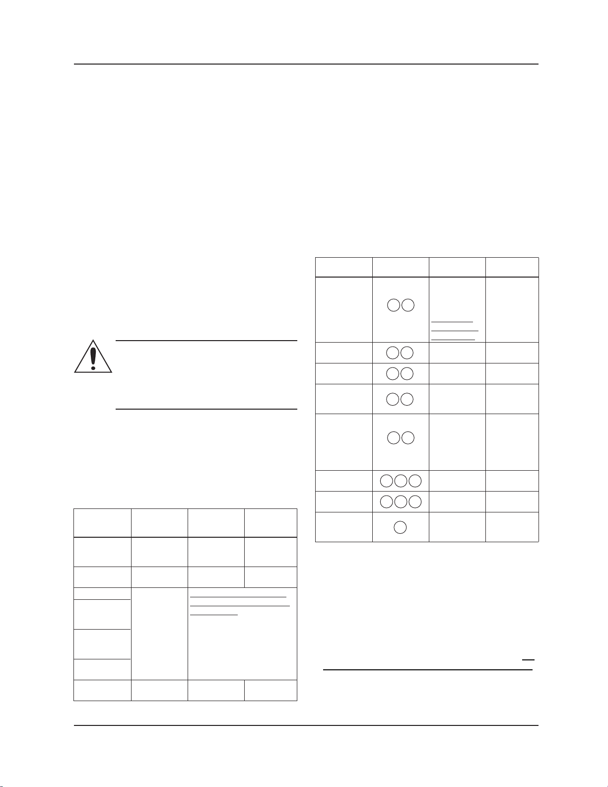
Once the lock is active, by pressing any button the drive
displays the symbol; unlocking the Control
Panel, the drive will display the symbol .
4.3.5 Sub-menus (parameters)
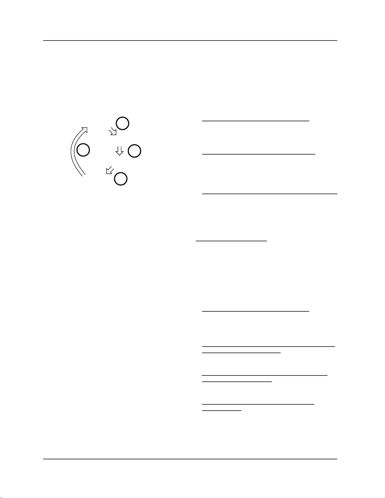
4.3.5.1 Dual pump operations settings
Each electronic drive can be congured to couple with
another drive, so that they start working in concert in
dual pump operation.
Prerequisites:
• Dual pump operation is available only when identical
pumps are used.
• Wire both pumps to terminals (15), (16) and (17) as
described in sec. 2.4 and sec. 2.5.6, connecting the
2x single-head pumps.
For a correct automatic conguration, follow the
subsequent procedure, by rst setting the pump
selected to be the master of the couple
1. Switch on the power supply to both the pumps
2. After few seconds, the drive will display the message
SING.
3. While this message (“SING”) is displayed, press
shortly one of the Setting buttons (5), in order to
congure the circulator as:
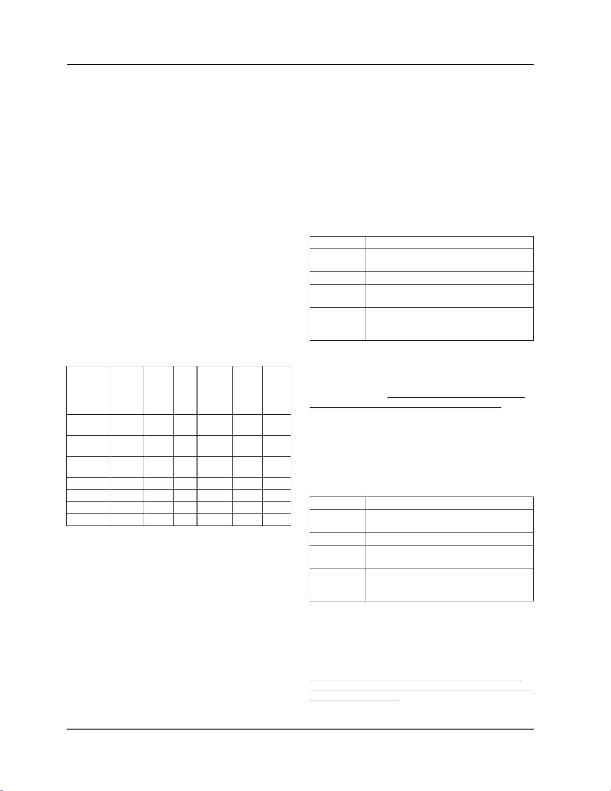
• Single Head Pump (factory default): the message
SING is ashing onto the Numeric Display (7).
• Dual Slave Pump: the message TUSL is ashing
onto the Numeric Display (7).
• Dual Master Pump: the message TUMA is ashing
onto the Numeric Display (6).
4. Press shortly the Parameter button (3) to conrm and
store the value selected.
The Numeric Display (7) stops ashing.
• When the Single Head Pump or Dual Slave Pump
conguration is nalized, the drive will proceed to the
next step as described in sec. 3, step 2.
• Only in case of Dual Master Pump, a new sub-
menu is made available (as described in the next
steps) for setting the dual pump operation
5. After few seconds, the drive will display the message
“BCUP”.
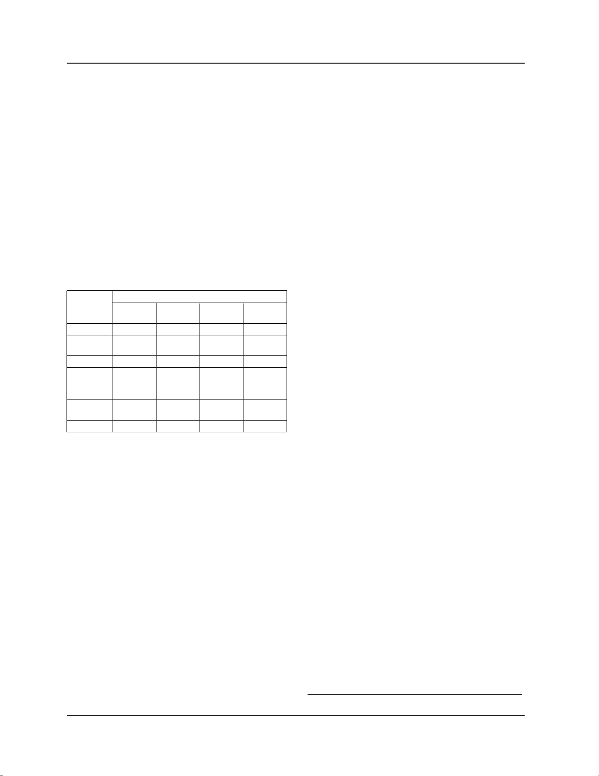
6. While this message (“BCUP”) is displayed, press
shortly one of the Setting buttons (5), in order to
congure the dual pump operation as:
Control Panel
CIRCULATOR
B&G 104450LF ECO-XL CIRCULATOR

Electronic Drive Manual 9
• Backup operation (factory default): the message
bCUP is ashing onto the Numeric Display (6).
In this conguration, only the master pump runs, while
the second pump starts in case of failure of the master
pump.
• Alternate operation: the message ALTE is ashing
onto the Numeric Display (6).
In this conguration, only one pump runs at a time.
The working time is switched every 24 hours so that
workload is balanced between both pumps. The
second pump starts immediately in case of failure of
the running pump. The 24 hour alternating time is
non-adjustable.
• Parallel operation: the message PArA is ashing onto
the Numeric Display (6).
In this conguration, both pumps run simultaneously
with the same set point. The master pump determines
the behavior of the full system and is able to optimize
the performance. To satisfy the required performance,
the master pump starts or stop the second pump
depending on the required head and ow.
• Forced parallel operation: the message FOrC is
ashing onto the Numeric Display (6).
In this conguration, both pumps always run
simultaneously at the same set point.
7. Press shortly the Parameter button (3) to conrm the
value selected.
The Numeric Display (6) stops ashing: the congura-
tion is nalized and the drive will proceed to the next
step as described in sec. 3, step 2.
Once the master pump is congured, the second pump
(slave) is then automatically congured by the master
pump. To verify this, the Remote (green) LED is
permanently lit.
In case the automatic conguration of the second pump
(slave) did not take effect (Remote LED not lit), repeat
the above procedure, from step 1 to step 4, conguring
the second pump to be a Dual Slave Pump.
NOTE:
Whenever two pumps, connected in Dual Pump
Operations, are required to communicate remotely with
a BMS or a generic external device, then the Optional
Communication Bus, described in sec. 2.5.7, must be
activated through the installation of an optional
module (see sec. 2.5.8) exclusively into the Master
pump of the couple.
4.3.5.2 Communication settings
Each electronic drive can communicate remotely
through a built-in RS485 port, as briey described in
sec. 2.5.6.
Referring to Figure 7 in the appendix, the communica-
tions settings are accessible following the subsequent
procedure.
1. Switch on the power supply to the pump
2. After few seconds, the drive will display the message
COMM.
3. While this message (“COMM”) is displayed, press
shortly the Parameter button (3) in order to congure
the subsequent parameters:
• Baud Rate: the message bAUd “BAUD” is displayed
onto the Numeric Display (7), allowing the communica-
tion port baud rate to be set to a specic value.
Available values for this parameter are:
- 4.8 kbps
- 9.6 kbps (factory default)
- 14.4 kbps
- 19.2 kbps
- 38.4 kbps (recommended for BACnet)
- 56.0 kbps
- 57.6 kbps.
• Protocol: the message PrOT “PROT” is displayed
onto the Numeric Display (6), allowing the user to select
a specic protocol on the communication port.
Available values for this parameter are:
- Modbus NOd “MOD” (factory default)
- BACnet bAC “BAC”.
• Address: the message Addr is displayed onto the Nu-
meric Display (6): by mean of it, the circulator address is
set to a specic value (1 is the factory default).
Available values for this parameter are:
- [1-247] (in case of Modbus protocol)
- [0-127] (in case of BACnet protocol)
• Module: the message NOdU “MODU” is displayed
onto the Numeric Display (6), allowing the user to select
one optional module in the drive.
Available values for this parameter are:
- None NONE (factory default)
- Wireless “WIFI”
- RS485 485
4. Press the Parameter button (3) to enter each sub-
menu, thus accessing to the next level.
5. Use the Setting buttons (5), in order to select the
desired value for every parameter
6. Press the Parameter button (3) to conrm and store
the value selected
7. Press the Control mode button (1) to exit each
sub-menu, thus returning to the previous level
If no buttons are pressed for 10 seconds, then the
pump exits the current menu and continues start-up
procedure. All the parameters changed without
conrmation are restored to former state.
Control Panel
CIRCULATOR
B&G 104450LF ECO-XL CIRCULATOR

Electronic Drive Manual
10
4.3.5.3 Differential pressure sensor
When an optional external differential pressure sensor
is connected to the circulator, as described in sec. 2.5.4,
a submenu is made available for setting the differential
pressure sensor’s parameters, as described in sec. 3.
Referring to Figure 7 in the appendix, the differential
pressure sensor’s settings are accessible by following
the procedure below.
1. Switch on the power supply to the pump.
2. After few seconds, the drive will display the message
PrES “PRES”.
3. While this message “PRES” is displayed, press
shortly the Parameter button (3) in order to congure
the subsequent parameter:
• Type: the message tYPE “TYPE” is displayed onto
the Numeric Display (7), allowing the user to
select a specic differential pressure range.
Available values for this parameter are:
- 0-15 PSID (0-1 bar) d01 (factory default)
- 0-30 PSID (0-2 bar) d02
4. Press the Parameter button (3) to enter each
sub-menu, thus accessing to the next level.
5. Use the Setting buttons (5), in order to select the
desired value for the parameter
6. Press the Parameter button (3) to conrm and store
the value selected
7. Press the Control mode button (1) to exit each sub-
menu, thus returning to the previous level
If no buttons are pressed for 10 seconds, the pump exits
the current menu and continues start-up procedure.
All the parameters changed without conrmation are
restored to former state.
5. Diagnostic codes
Referring to Figure 7, as briey described in sec. 4.1:
• In case of any alarm that allows the pump to continue
running, the display shows an alarm code as given
below and the status indicator becomes orange (see
sec. 5.1).
• In case of a failure that stops the pump, the display
shows the error code (see sec. 5.2) permanently
and the status indicator becomes red.
5.1 Display messages
Table 1: Default
Operating LEDs / Display Cause
Power On Pump powered
All LEDs and display On Start-up of the pump
Status Green light Pump is working
properly
Remote On Remote communication
is activated
Table 2: Fault messages
Operating LEDs / Cause Solution
Display
Power Off Pump is not Check
connected or is connection
incorrectly
connected
Power failure Check power
supply and
circuit breaker
Status light Orange Alarm for Check the
system problem displayed
alarm code and
nd cause from
section 5.3.
Status light Red Pump failure Check the
displayed error
code and nd
the cause from
section 5.2.
Remote Off Remote If the commu-
communication nication does
is deactivated not work,
check the
connection
and the
conguration
parameters for
communica-
tion on the
external
controller.
Diagnostic Codes
CIRCULATOR
B&G 104450LF ECO-XL CIRCULATOR

Electronic Drive Manual 11
5.2 Fault and error codes
(Red LED)
Error Cause Solution
code
E01 Internal communication Restart the pump1
lost
E02 High motor current Restart the pump1
E03 DC Bus overvoltage Indicates excessive
power through the
pump. Conrm
system setup, verify
correct position and
operation of check
valves.
E04 Motor stall Restart the pump1
E05 Data memory corrupted Restart the pump1
E06 Voltage supply out of Check the electrical
operating range system voltage and
wiring connection.
E07 Motor thermal protection Check the presence
trip of foreign material
around impeller and
rotor that cause
overload. Check
installation conditions
and temperature of
the water and
ambient air. Wait until
the motor is cooled.
If the error persists
try to restart
the pump1.
E08 Inverter thermal protection Check installation
trip conditions and
ambient air
temperature.
E09 Hardware error Restart the pump.
E10 Dry run Check for system
leakage or ll the
system.
5.3 Alarm codes (Orange LED)
Alarm Cause Solution
code
A01 Fluid sensor malfunction Switch off the pump
for 5 minutes and
then power on. If the
problem persists,
contact local B&G
representative.
A02 High temperature of the Check water
uid temperature value
A03 Automatic speed reduction Check installation
to prevent inverter conditionsand rectify
overheating status of the system
A05 Data memory corrupted Switch off the pump
for 5 minutes and
then power on. If the
problem persists,
contact local B&G
representative.
A06 External temperature Check the probe and
probe malfunction the connection to the
pump
A07 External pressure sensor Check the sensor
malfunction and the connection to
the pump
A08 Cooling fan failure (Only Check for the
on 2 HP and larger presence of foreign
models) bodies which could
lock the fan rotation.
Switch off the pump
for 5 minutes and
then power on. If the
problem persists,
contact service.
A12 2–pump communication If both pumps show
lost the A12 alarm, check
the connection
between the pumps.
If one of the pumps is
switched off or shows
another error code,
check section 5.1 to
nd the problem.
A20 Internal alarm Switch off the pump
for 5 minutes and
then power on. If the
problem persists,
contact local B&G
representative.
Diagnostic Codes
1Switch off the power for 5 minutes and then power on. If the problem persists, contact service.
CIRCULATOR
B&G 104450LF ECO-XL CIRCULATOR

Electronic Drive Manual
12
5.4 Faults, causes, and remedies
The pump does not start
Cause Remedy
No power. Check the power supply and
ensure that it is properly terminated
to the pump power.
Tripped circuit Reset power supply circuit breaker
breaker or ground- and determine cause for
fault protection overload.
device or the
circuit breaker.
The pump starts but the thermal protection is
triggered after a short time
Cause Remedy
Incorrect wiring Check and replace the components
size or circuit as necessary.
breaker rating not
suitable for motor
current.
Thermal overload Check the pump working
protection due to conditions.
excessive input.
Missing a phase in Verify continuity and ensure
the power supply. proper wiring connections.
The pump is noisy
Cause Remedy
Not thoroughly Switch off the pump and after
vented. 30 seconds switch on again to
restart the automatic air-venting
procedure.
Cavitation due to Increase the system
insufcient suction suction pressure within the
pressure. admissible range.
Foreign objects in Clean the system.
pump.
Worn out bearing Replace pump.
6.1 External temperature sensor
As briey described in sec. 2.5.5, the circulator can be
equipped with an external KTY83 temperature probe
(1KΩ at 77F) for the purpose of measuring an absolute
or a differential uid temperature, in temperature
dependent or temperature inuenced control modes.
The sensor may be strapped to the pipe or inserted in
an immersion well for sensing hot or cold water. The
sensor may also be used to sense air temperature in an
air duct.
Multiple sensors may be connected in parallel-series
conguration for averaging temperature measurements.
Accessories
6. Accessories
Sensor
placed
in well
Use heat
conducting
compound
1/2” NPT Immersion
well
Sensors
NOTE:
TO SETUP PARAMETERS AND ADJUST FLUID
TEMPERATURE DEPENDENT CONTROL MODES,
THROUGH MODBUS OR BACnet PROTOCOLS,
REFER TO THE FOLLOWING TECHNICAL
BROCHURES POSTED ON THE B&G WEBSITEAT:
www.bellgossett.com:
P0002563 ecocirc XL Modbus Parameters
P0002566 ecocirc XL BACnet Objects
CIRCULATOR
B&G 104450LF ECO-XL CIRCULATOR

Electronic Drive Manual 13
6.1.2 Fluid temperature dependent Control
modes – Circulator Control Panel
The PC based software application “Circulator Control
Panel” may be used to congure temperature depen-
dent control modes. Refer to Advanced Tab to access
temperature based control parameters.
A suitable USB-RS485 cable must be used for a wired
connection from a PC to the pump terminals 15-16-17.
The USB-RS485 cable may be sourced at
http://www.ftdichip.com or through any other source
meeting those requirements.
Accessories
CIRCULATOR
B&G 104450LF ECO-XL CIRCULATOR

Electronic Drive Manual
14
6.2 Wireless Module
Referring to Figure 8 in the appendix, after the module
has been connected, congure it by setting the
parameter “Module” to the value “Wireless”, as
described in sec. 4.3.5.2.
6.2.1 Wireless module use
When the wireless module is assembled into ecocirc XL,
and correctly congured, it generates a (type 902.11n)
wireless network accessible (by a mobile phone, tablet
or a PC) using data (S/N and PWD) printed on the label
at the side of the circulator’s drive
In particular,
• Network name: “xylemecoxl”_______S/N_______”
where S/N is an 8 character word
• Password: “xylem_______PWD_______” where PWD
is an 8 character word
To access the circulator’s web pages using a browser
(on the connected external device), use the web address
“https://xylemecoxl” or type directly “192.168.1.10”
6.3 RS485 Module
Referring to Figure 8 in the appendix, after the module
is connected, congure it by setting the parameter
“Module” to the value “RS485”, as described in
sec. 4.3.5.2
Accessories
CIRCULATOR
B&G 104450LF ECO-XL CIRCULATOR

Electronic Drive Manual 15
7. Appendix
Figure 4
Figure 5
1
2
3
L
N
115V
L1
L2
208-230V CB
(circuit
breaker)
Appendix
CIRCULATOR
B&G 104450LF ECO-XL CIRCULATOR

Electronic Drive Manual
16
Figure 6
Start / Stop
20
1918
17
1615
14
1312
11
10987654321
CNLNO 15V S+S- P+ P- T+ T- ABGND AB GND
Figure 7
9
8
7
6
5
4
2
1
3
Appendix
Setting Buttons - Arrows
Control Modes LEDs
Control Mode Button
Parameters Button
CIRCULATOR
B&G 104450LF ECO-XL CIRCULATOR

Electronic Drive Manual 17
Figure 8
Appendix
Wireless Module or
RS485 Module
Terminal #21
CIRCULATOR
B&G 104450LF ECO-XL CIRCULATOR

1) The tissue in plants that brings water upward from the roots;
2) a leading global water technology company.
We’re a global team unied in a common purpose: creating innovative solutions to
meet our world’s water needs. Developing new technologies that will improve the way
water is used, conserved, and re-used in the future is central to our work. We move,
treat, analyze, and return water to the environment, and we help people use water
efciently, in their homes, buildings, factories and farms. In more than 150 countries, we
have strong, long-standing relationships with customers who know us for our powerful
combination of leading product brands and applications expertise, backed by a legacy
of innovation.
For more information on how Xylem can help you, go to www.xyleminc.com
Xylem
Xylem Inc.
8200 N. Austin Avenue
Morton Grove, IL 60053
Tel (847) 966-3700
Fax (847) 965-8379
www.bellgossett.com
Bell & Gossett is a trademark of Xylem Inc. or one if its subsidiaries.
© 2015 Xylem Inc. P0002554 REV1 May 2015
CIRCULATOR
B&G 104450LF ECO-XL CIRCULATOR
Other manuals for Bell & Gossett ecocirc XL Series
2
Table of contents
Other Xylem DC Drive manuals