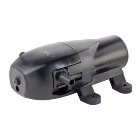
Parts list (model 3000)
Disassembly specific to 2000 lip seal model:
To avoid inducing leaks, remove the lip seal from the body only if
being replaced. To remove the seal from the body seal bore, remove
the pump body from the motor by loosening and removing the 2 off
M5 screws using an 8mm (5/16”) spanner. With the body removed,
manually press the lip seal out the front of the body seal bore.
Alternatively the lip seal can be removed from the front of the body
using a small screwdriver to pries out the seal from the seal bore.
Ensure not the scratch the seal bore with the screwdriver as this will
create a leak path for the fluid to escape the pump. With the body
removed, the slinger can be accessed and removed. This
component deters any leaking fluid from entering the motor; a small
but important part of the pump. Replace it if perished or it no longer
grips the shaft. Clean the body and slinger before re-assembly.
Component cleaning should be done with soap and water. Do not
clean elastomers with solvents.
Disassembly specific to 3000 mechanical seal model:
To avoid inducing leaks, remove the mechanical seal from the pump
only if being replaced. To remove the seal from the pump, remove
the pump body from the motor by loosening and removing the 2 off
M5 screws using an 8mm (5/16”) spanner. On removal, the static
face of the seal (white ceramic) will be left in the body, the dynamic
face of the seal (metal encased carbon) will be on the shaft. Press
the static face out the back of the body, taking care not to scratch
the seal bore. The O ring on the dynamic metal case circumference
is the slinger. Remove the slinger. Slide off the dynamic seal face.
Whilst inspecting the mechanical seal faces, take care not to touch,
scratch or otherwise damage the shiny lapped seal surfaces. If the
seal leaks, look for radial grooves, large chips or scratches
traversing in the carbon seal face. Also look for effective grip of the
elastomer on the shaft. If no fault can be found, the leak may not be
from the mechanical seal. Finally remove the plastic Support
washer. The support washer optimizes the mechanical seal function
and is an important part of the design.
Reassemble the pump in the reverse order to the disassembly.
Specific to 2000 lip seal model
Position the slinger to within 4mm (3/16”) of the motor end cover.
Press the lip seal (“closed” face first) into the pump body seal bore.
Ensure it is fully seated. Lubricating with soapy water may help
seating. Do not use grease.
Specific to 3000 mechanical seal model:
Place the support washer over the motor shaft and rest against the
motor bearing. Place the O ring slinger centrally over the dynamic
seal face metal casing and slide that over the motor shaft to sit
against the support washer. Push the static seal face fully into the
body seal bore. The above two actions will be eased using soapy
water as a lubricant. Do not use grease. Ensure the seal faces are
clean and free of debris, grit and other contaminants which will
cause the seal to leak.
Secure the pump body to the motor by fitting and tightening the 2 off
M5 screws using an 8mm (5/16”) spanner. Tighten to 3.7-4.2Nm
(2.7-3.1 ftlb). Secure the Cam to the body with cam screw and O
ring. Tighten to 3.7-4.2 Nm (2.7-3.1ftlb). Do not over tighten as this
will potentially cause leaks due to over compression of the O ring.
The impeller hub single flat mates with the shaft single flat. Lubricate
the impeller and body impeller bore with Jabsco impeller lubricant
43000-0802 (lubricant and end cover O ring included in impeller kit
6303 & 7273-0003-P). Insert the impeller using a clockwise twisting
movement. Place the end cover O ring into the body O ring groove.
Smearing the O ring with lubricant helps keep it in place whilst the
end cover is fitted. Secure the end cover to the body with the 4 off
end cover M5 screws using an 8mm (5/16”) spanner. Tighten to 3.7-
4.2 Nm (2.7-3.1ftlb). Re-install to the system secure electrical and
physical connections and follow the “initial startup procedure”
detailed above
8. CUSTOMER SUPPORT
If any pump units for any reason need to be returned,
please ensure the pump unit has been fully drained before
returning. Please contact customer services for more
information
9. ENVIRONMENTAL PROTECTION
Due consideration to environmental issues have
been made within the design and manufacturing
process of this product without compromising
product performance and value.
WEEE Policy
The Waste Electrical and Electronic Equipment
Directive (WEEE Directive) is a European
Community Directive 2012/19/EU on waste
electrical and electronic equipment which
became European Law in February 2003. The
WEEE Directive set collection, recycling and recovery targets for all
types of electrical goods.
Xylem Water Services Limited has identified that their product range
comes under Category 6 (Electrical tools) and as such will undertake
their responsibilities in line with the above directive and will fulfill
their legal obligation by means of joining a compliance scheme.
All products are identified by means of the Wheelie bin logo as laid
down in the above directive.
The Xylem Water Services Limited WEEE producer registration
number is WEEE/RM07081
Full details of scheme can be found @ Valpak Limited
Unit 4, Montague House, Stratford-upon-Avon Business and
Technology Park, Banbury Road, Stratford-upon-Avon,
At the end of your product and accessories life, it must not be
discarded as domestic waste.
Please contact your distributor / supplier for further information.
For end users outside of the EU consult applicable regulations.
This product should only be dismantled for recycling by an
authorized recycling company.
*Mechanical Seal (static)
Mechanical Seal (Dynamic)
