manuals.online logo
Brands
  1. Home
  2. •
  3. Brands
  4. •
  5. Xylem
  6. •
  7. Water Pump
  8. •
  9. Xylem JABSCO 11860 Series User manual

Xylem JABSCO 11860 Series User manual

Models 11860, 11870-Series
SELF- RIMING UM S
ELECTRO-MAGNETIC CLUTCH UNIT
FEATURES
Body: Bronze
Impeller: Nitrile
Shaft: Stainless Steel
Seal: Carbon-Ceramic, Face Type
orts: 11860-Series, 1" NPT Internal
11870-Series, 1-1/4" NPT Internal
Bearings: Shielded Ball Bearings
Weight: 11860-Series, 15 lb (6.8 kg) Approx.
11870-Series, 19-1/2 lb (8.9 kg) Approx.
Clutch
Model Volt/Belt Cam Impeller Insert
11860-0005 12 / 2-A Brass Nitrile Brass
11860-0045 12 / 1-B Brass Nitrile Brass
11860-0006 24 / 2-A Brass Nitrile Brass
11860-0046 24 / 1-B Brass Nitrile Brass
11870-0005 12 / 2-A Brass Nitrile Brass
11870-0045 12 / 1-B Brass Nitrile Brass
11870-0006 24 / 2-A Brass Nitrile Brass
11870-0046 24 / 1-B Brass Nitrile Brass
11870-0007 32 / 2-A Brass Nitrile Brass
A LICATION
MARINE: Pumping bilges, Washdowns, Circulating
water in bait tanks, Utility dock-side pump.
INDUSTRIAL: Circulating and transferring, Velocity-
mixing, Pumping machine tool coolants, Return spill,
Sump drainage, Chemicals, Pharmaceuticals, Soap,
Liquors, Ink, Dyes, Alcohol, Various acids, Tanning
Liquors, Glycerine, Brine, etc.
FARMING: Pumping water stock, Pumping water from
shallow wells and cisterns.
PLUMBING AND HOME EMERGENC USE: Pumping
out flooded basements, Cesspools, Sumps, Water
heaters and water closets, Drains and sinks, Draining
fishponds and pools.
PUBLIC UTILITIES AND MUNICIPALITIES: Under the
hood mounting on service trucks for draining meter
boxes, manholes, excavations; For pollution control and
watering for dust control.
INSTALLATION
Pump may be mounted in any position. Intake and
discharge ports are determined by the direction of shaft
rotation (refer to dimensional drawing). Before installing,
energize clutch and turn pump shaft in direction of shaft
rotation. Drive pump with two “A” size belts or one “B”
size belt. Avoid dry-running by using Vacuum Switch
Model 4732-0000 for automatic shutoff.
WIRING
Connect wires as shown for manual on-off operation. Install
appropriate size fuse (see Electrical Specification Chart) in
positive lead as close to power source as possible. For
complete wiring instruction, see diagram on last page.
Connect wires as shown for manual on-off operation.
ELECTRICAL S ECIFICATIONS
Voltage Amp Draw Fuse Size
12 47
24 24
32 1.5 2
O ERATION
Pump will self-prime at low or high speeds. Make sure
that all connections are airtight. 12 Volt models are
equipped with mechanical clutch engagement screws in
case of electrical failure. To mechanically engage clutch,
loosen locking nuts, tighten allen head screws and
retighten locking nuts. Reverse procedure to disengage
clutch. If the mechanical engagement feature is not
Injury hazard. Exposed pulleys and belts can
cause injury. Install shield around pulleys and
belts. Stay clear while machinery is operating.
WARNING
!
MODEL 11860-SERIES
11870-SERIES
SERVICE INSTRUCTIONS
IMPELLER REPLACEMENT: Remove end cover gasket. Pull
impeller out by grasping hub with pliers. With rotary motion in the
direction the pump will be turning, push the impeller into the impeller
bore. A light coating of grease in the impeller bore will protect the
impeller during initial dry start up. Install gasket and end cover.
SHAFT SEAL REPLACEMENT, 11870-SERIES: Remove end cover,
gasket and impeller, as outlined above. Loosen cam screw several turns.
Give cam screw a couple of sharp raps with the handle of the screwdriver
to loosen the cam from the impeller bore. Remove the cam screw and
cam (clean sealant from cam and impeller bore). Remove wearplate with
hooked wire. Remove marcel washer, seal assembly and seal s eat
assembly from seal bore with hooked wire, taking care not to scratch
shaft or seal seat bore. Clean shaft surfaces behind splines and inspect
for scratches or wear. Replace if necessary. Before installing new seal
parts, clean any oil or grease from carbon and ceramic seal faces. Dip
seal seat and gasket assembly in water and press into seal bore
with boot first. Dip carbon seal assembly in water and install over shaft,
carbon towards ceramic seal seat, until it bottoms firmly against ceramic
seat. Slide marcel spring washer over shaft and against the rubber boot
(washer) on carbon seal assembly. Replace wearplate, aligning notch
with dowel pin in body. Apply sealant to top surface of cam and cam
screw threads and install cam in impeller bore. Snug up but do not
tighten cam screw. Replace impeller, gasket and end cover as outlined
above. Tighten end cover screws. Tighten cam screw.
SHAFT SEAL REPLACEMENT, 11860-SERIES: Refer to major
repair instructions.
FIELD COIL REPLACEMENT: Remove drive belts from pulley. Remove
center bolt and washer from pulley (it may be necessary to remove end
cover to hold impeller from turning, while removing center pulley bolt).
Tap pulley with soft mallet to remove from shaft taper. Remove 3 bolts
and washers holding field coil to adaptor (11870) or body (11860).
Remove and replace field coil, tightening the 3 bolts securely. With drive
key in place in shaft, replace pulley assembly. Secure to shaft, replace
pulley assembly. Secure to shaft with center bolt and washer (again, it
may be necessary to hold the impeller from turning to tighten center
bolt). Replace drive belts. Do not over tighten belts. A deflection of 1/2"
midway between pulleys is generally considered normal.
MAJOR REPAIR: Remove pump from installation for major repair.
Disassembly: Remove end cover, gasket,impeller, cam and wearplate
as outlined in shaft seal replacement, 11870-Series. Remove clutch as
outlined in field coil replacement. Model 11870-Series: Use a punch to
drive roll pins (key 17) in toward shaft approximately 3/8" (10mm).
Remove clutch adaptor from body. Punch roll pin out of adaptor. Model
11860-Series does not have adaptor, clutch is secured directly to body.
Remove bearing to body retaining ring. Support bearing end of body on
arbor press platten. Press on impeller end of shaft to remove shaft and
bearing assembly from body. Use screwdriver to pry inner bearing seal
from body. Take care not to scratch or damage body bore.
11860-SERIES: Remove seal seat assembly from shaft. Support
impeller end of body on arbor press platten and, using suitable tube,
press seal out of seal bore towards impeller end.
11870-SERIES: Remove slinger from drain area. Carbon portion of
the seal assembly will be freed from shaft when shaft is remove from
body. Press seal seat assembly from bearing bore end towards
impeller bore.Remove bearing to shaft retaining ring. Support bearing
and press on clutch drive end of shaft to remove shaft from bearing.
ASSEMBL : Support inner race of bearing on arbor press platten.
Oil shaft, insert drive end of shaft into bearing and press shaft through
bearing until it bottoms firmly against shoulder.Install shaft to bearing
until it bottoms firmly against shoulder. Install shaft to bearing retaining
ring in groove of shaft. Support impeller bore end of pump on arbor
press platten. Lubricate bearing seal with grease and press into bearing
seal bore, flush with bearing bore shoulder, with lip facing away from
bearing bore. For 11870-Series only: Insert slinger in drain slot, to be
picked up by shaft during shaft/bearing assembly. Insert splined end
of shaft through bearing seal (and slinger on Model 11870-Series).
Press on outer bearing race to assemble shaft/bearing assembly into
body, bottoming bearing firmly against bearing bore shoulder.Install
body to bearing retaining ring in groove in body with flat side against
bearing. For 11870-Series only: Install clutch adaptor in bearing bore.
If re-using adaptor previously disassembled from pump, line up dowel
pin holes during assembly of adaptor to body. If installing new adaptor
(which does not have pre-drilled dowel pin holes), insert into bearing
bore until it bottoms and use dowel pin holes in body to pilot drill dowel
pin holes through adaptor in two places, 180° apart. Clean any brass
chips from bearing area. Press roll pins into body to secure adaptor.
Attach field coil to adaptor (11870-Series) or body (11860-Series) with
three round head bolts. Turn body over and support on field coil.
11860-SERIES: Dip seal seat assembly, consisting of ceramic seal
seat and rubber washer, in water and push over shaft, with shiny side
of ceramic facing impeller bore, until bottoms firmly against shaft
shoulder. Press on outside edge of seal case with carbon seal face
towards ceramic seat to install seal assembly in seal bore. Press flush
with bottom of impeller bore.
11870-SERIES: Assemble rubber boot over ceramic seal seat so that
shiny surface of seal seat is outwards. Dip assembly in water and
insert into seal bore. Press firmly but carefully on seal seat until it
bottoms against shoulder of seal bore. Check to see that the seal seat
assembly remains in position and does not “pop” back out. A slight
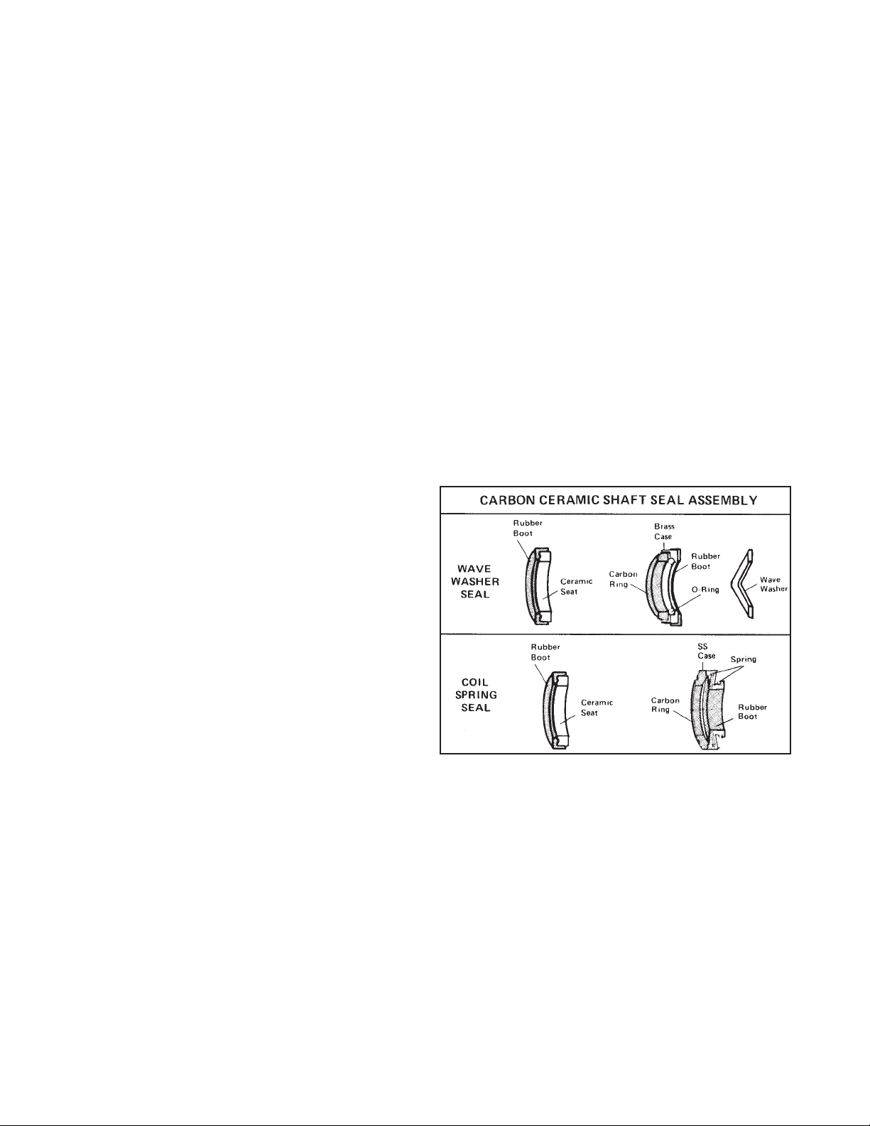
twisting motion while pressing will seat it firmly in position.In this
pump, either a wave washer seal or coil spring carbon seal may be
used. The wave washer is used only if the carbon portion of the seal
does not have a coil spring attached.
Inspect shaft and seal seat bore to be sure sealing surfaces are free
of nicks or scratches. Clean shaft surface behind splines to ensure
proper O-ring seal on shaft. Apply light film of grease on shaft surface
behind spline area. Slide carbon ring assembly, with carbon facing
ceramic, over the shaft and firmly up against the ceramic seat. If
carbon portion of seal does not have an integral coil type tensioning
spring, slide wave washer over the shaft and against the rubber boot
on metal case containing O-ring and carbon. Install wearplate in
bottom of impeller bore, locating slot in outside edge of wearplate over
dowel pin in body. Apply a small amount of sealant to surface of cam
and cam screw threads and install cam in impeller bore. Edge of cam
should be flush with flange face of body. With a rotary motion in the
direction the pump will be turning, push the impeller into the impeller
bore until it is firmly bottomed. Turn body over to install clutch pulley
assembly. Press key into shaft. Position clutch/pulley assembly on
shaft aligning key with slot in pulley hub. Secure with bolt and washer.
To tighten bolt securely, it may be necessary to hold the impeller to
prevent the shaft from turning. Turn pump assembly over. Dip gasket
in water, position on pump flange face, install end cover and secure
with end cover screws.
ARTS LIST
Qty. 11860-Series 11870-Series
Key Description Req. Part No. Part No.
1 Screw End Cover (3 Per it) 2 91003-0010 –
Screw End Cover (3 Per it)) 2–91005-0040
2 End Cover 1 11831-0000 12062-0000
3 Gasket 1 890-0000 816-0000
4 Impeller Nitrile, Brass** 1 920-0003 836-0003
5 Wearplate 1 7868-0000 2574-0000
6 Body 1 11864-0000 18753-0585
7 Screw Cam (3 Per it) 1 91004-0090 91005-0040
8 Cam, Brass 1 934-0000 834-0001
9 Pipe Plug 2 92650-0070 92650-0070
10 Slinger 1 3180-0000 3181-0000
11 Seal (Bearing)* 1 913-0000 817-0000
12 Ball Bearing (Pump) 1 92600-0540 92600-0040
13 Retaining Ring (Brg to Body) 1 18724-0000 18712-0000
14 Retaining Ring (Brg to Shaft) 1 18713-0000 18711-0000
15 Shaft 1 11867-0000 11877-0000
16 Seal (Shaft) 1 96080-0080 6407-0010
17 Roll Pin (Adaptor) 2–93100-0160
18 Adaptor 1–11876-0000
19 ey (Clutch Drive) 1 91401-0100 91401-0100
20 Clutch Assy. Complete 12 V – 2-A Grooves 1 92300-0030 92300-0030
12 V – 1-B Groove 18753-0493 18753-0493
24 V – 2-A Grooves 92300-0061 92300-0061
24 V – 1-B Groove 18753-0494 18753-0494
32 V – 2-A Grooves – 92300-0050
21 Replacement Field Coil 12 V 98022-0500 98022-0500
24 V 98022-2155 98022-2155
32 V 98022-0510 98022-0510
Service it Nitrile Impeller 90118-0003 90062-0003
* Use on pre 2002 models. Date code 01H or earlier.
**Special application model 11860-7001, use Impeller 17937-0001, Service it 90118-0001
THE PRODUCTS DESCRIBED HEREIN ARE SUBJECT
TO THE JABSCO ONE YEAR LIMITED WARRANTY,
WHICH IS AVAILABLE FOR YOUR INSPECTION
UPON REQUEST.
TABULATION OF DIMENSIONS (Inches and Millimeters)
Model ABCD-1 D-2 EFGH I JKLMNO Q
11860 6-3/16 5-3/8 4-29/32 3-9/16 3-7/8 5/8 1-5/16 3/4 1-1/2 1-9/16 3-1/8 2413/32 1/4 1-7/8 2-1/2 4-3/4
Series 157 137 125 90 98 16 33 19 38 40 79 51 102 10 6 48 64 21
11870 8-3/16 6-1/16 7-1/16 5-1/4 5-9/16 5/8 —— 1-7/32 2-5/16 2-1/4 4-1/2 2-3/4 5-1/2 13/32 5/16 2-9/16 3-13/16 5-7/8
Series 208 154 179 133 141 16 31 59 57 114 70 140 10 8 65 97 149
RSTUV
2-3/8 1" 7 ————
60 NPT 178
2-15/16 1-1/4" 7 3/16 1-1/2
75 NPT 178 21 38
CA ACITY TABLES
Total Head 500 R M 1160 R M 1750 R M 2450 R M 3000 R M
kg per feet of meters of
psi sq cm water water GPM LPM HP GPM LPM HP GPM LPM HP GPM LPM HP GPM LPM HP
4.3 0.3 10 3.0 6.0 22.7 1/4 14.8 56.0 1/3 23.3 88.2 3/4 32.5 123.0 1 34.8 131.7 1-1/2
11860 8.7 0.6 20 6.1 5.5 20.8 1/4 14.1 53.4 1/2 22.3 84.4 3/4 31.8 120.4 1-1/2 34.2 129.5 1-1/2
Series 17.3 1.2 40 12.2 4.0 15.1 1/4 12.0 45.4 1/2 19.5 73.8 3/4 28.5 107.9 1-1/2 32.5 123.0 2
26.0 1.8 60 18.3 ———8.8 33.3 3/4 15.0 56.8 1 23.5 89.0 1-1/2 29.8 112.8 2
34.6 2.4 80 24.4 —————————17.0 64.4 1-1/2 23.8 90.1 2
4.3 0.3 10 3.0 18.0 68.1 1/2 41.0 155.2 1 62.0 234.7 1-1/2 ——————
11870 8.7 0.6 20 6.1 17.0 64.4 1/2 40.0 151.4 1 60.0 227.1 1-1/2 ——————
Series 17.3 1.2 40 12.2 14.0 53.0 1/2 37.0 140.1 1-1/2 55.0 208.2 2 ——————
26.0 1.8 60 18.3 ———30.0 113.6 1-1/2 50.0 189.3 2 ——————
34.6 2.4 80 24.4 ——————40.0 151.4 3 ——————
Remote Control Engine Driven Pump
(While engine is running) Remote Control and Automatic Engine Driven Bilge Pump
(While engine is running)
REMOTE CONTROL: Install a pushbutton switch at one or more
locations (multiple switches should be wIred parallel). Depress
pushbutton for 2 seconds. If there is water in bilge, pump will operate
until dry, at which time vacuum switch will stop pump. If no water is in
bilge, pump will stop when pushbutton is released.
AUTOMATIC BILGE PUMP: Install No. 30295-Series Automatic Bilge
Pump Switch where it will energize clutch at maximum high water level
in bilge. When water raises switch float, pump will start. Vacuum switch
will maintain closed circuit until bilge is pumped dry. Pump will
automatically stop, preventing impeller damage.
Check out the collection of boat parts & hardware we offer.

This manual suits for next models

10

Other Xylem Water Pump manuals

Xylem Bell & Gossett 60 Series User manual

Xylem

Xylem Bell & Gossett 60 Series User manual

Xylem Bell & Gossett e-80SCXL Series User manual

Xylem

Xylem Bell & Gossett e-80SCXL Series User manual

Xylem GOULDS AC8743 User manual

Xylem

Xylem GOULDS AC8743 User manual

Xylem FLOJET VFLO 5.0 User manual

Xylem

Xylem FLOJET VFLO 5.0 User manual

Xylem FLOJET 4105 Series User manual

Xylem

Xylem FLOJET 4105 Series User manual

Xylem Bell & Gossett VSC Series User manual

Xylem

Xylem Bell & Gossett VSC Series User manual

Xylem IM127R07 Manual

Xylem

Xylem IM127R07 Manual

Xylem FLOJET 4105 Series User manual

Xylem

Xylem FLOJET 4105 Series User manual

Xylem Goulds 3642 User manual

Xylem

Xylem Goulds 3642 User manual

Xylem FloJet 3426 Series User manual

Xylem

Xylem FloJet 3426 Series User manual

Xylem GOULDS 45HB-70HB Operating instructions

Xylem

Xylem GOULDS 45HB-70HB Operating instructions

Xylem FLOJET R3426-500 User manual

Xylem

Xylem FLOJET R3426-500 User manual

Xylem Bell & Gossett e-80 Series User manual

Xylem

Xylem Bell & Gossett e-80 Series User manual

Xylem Rule LoPro LP900D User manual

Xylem

Xylem Rule LoPro LP900D User manual

Xylem Lowara LS Series Manual

Xylem

Xylem Lowara LS Series Manual

Xylem Lowara Sekamatik 200 Series General instructions

Xylem

Xylem Lowara Sekamatik 200 Series General instructions

Xylem Flygt 3060 User manual

Xylem

Xylem Flygt 3060 User manual

Xylem Lowara Scuba Series Original instructions

Xylem

Xylem Lowara Scuba Series Original instructions

Xylem GOULDS 2GFK2412H User manual

Xylem

Xylem GOULDS 2GFK2412H User manual

Xylem JABSCO Ballast SuperKing User manual

Xylem

Xylem JABSCO Ballast SuperKing User manual

Xylem G&L A-C 9100 Series User manual

Xylem

Xylem G&L A-C 9100 Series User manual

Xylem LOWARA F 1-2 Manual

Xylem

Xylem LOWARA F 1-2 Manual

Xylem Flygt 5530 User manual

Xylem

Xylem Flygt 5530 User manual

Xylem Lowara Z8 Series User manual

Xylem

Xylem Lowara Z8 Series User manual

Popular Water Pump manuals by other brands

Graco Husky 1050HP Operation

Graco

Graco Husky 1050HP Operation

ARO EXTRUSION PUMP NP623XXXXR8-XX Operator's manual

ARO

ARO EXTRUSION PUMP NP623XXXXR8-XX Operator's manual

Wallenstein PTO62 installation instructions

Wallenstein

Wallenstein PTO62 installation instructions

Conel FLOW Series operating instructions

Conel

Conel FLOW Series operating instructions

Initiative Engineering edose Operation and maintenance manual

Initiative Engineering

Initiative Engineering edose Operation and maintenance manual

Flotec FP4800 Series owner's manual

Flotec

Flotec FP4800 Series owner's manual

Flux PTB 11 ATEX 5009 X Original attachment

Flux

Flux PTB 11 ATEX 5009 X Original attachment

Zoeller 135-0006 installation instructions

Zoeller

Zoeller 135-0006 installation instructions

Pentair NOCCHI CM Series manual

Pentair

Pentair NOCCHI CM Series manual

Graco P06DCK Instructions-parts list

Graco

Graco P06DCK Instructions-parts list

Wilo MVIL Installation and operating instructions

Wilo

Wilo MVIL Installation and operating instructions

INOXPA ESTAMPINOX EFI Installation, service and maintenance instructions

INOXPA

INOXPA ESTAMPINOX EFI Installation, service and maintenance instructions

Agilent Technologies InfinityLab LC Series user manual

Agilent Technologies

Agilent Technologies InfinityLab LC Series user manual

Subaru RPX-65011 Parts and owners manual

Subaru

Subaru RPX-65011 Parts and owners manual

Star 3STHALC instruction manual

Star

Star 3STHALC instruction manual

Craftsman 390.304692 owner's manual

Craftsman

Craftsman 390.304692 owner's manual

M&C MP Series instruction manual

M&C

M&C MP Series instruction manual

SPERONI SVM 90 BR instruction manual

SPERONI

SPERONI SVM 90 BR instruction manual

manuals.online logo
manuals.online logoBrands
  • About & Mission
  • Contact us
  • Privacy Policy
  • Terms and Conditions

Copyright 2025 Manuals.Online. All Rights Reserved.