Yaesu G-550 User manual

INSTRUCTION
MANUAL
G-550
VERTEX STANDARD CO., LTD.
4-8-8 Nakameguro, Meguro-Ku, Tokyo 153-8644, Japan
VERTEX STANDARD
US Headquarters
17210 Edwards Rd., Cerritos, CA 90703, U.S.A.
International Division
8350 N.W. 52nd Terrace, Suite 201, Miami, FL 33166, U.S.A.
YAESU EUROPE B.V.
P.O. Box 75525, 1118 ZN Schiphol, The Netherlands
YAESU UK LTD.
Unit 12, Sun Valley Business Park, Winnall Close
Winchester, Hampshire, SO23 0LB, U.K.
YAESU GERMANY GmbH
Am Kronberger Hang 2, D-65824 Schwalbach, Germany
VERTEX STANDARD HK LTD.
Unit 5, 20/F., Seaview Centre, 139-141 Hoi Bun Road,
Kwun Tong, Kowloon, Hong Kong


PAGE 1
G-550 INSTALLATION MANUAL
YAESU G-550
MEDIUM-DUTY ANTENNA ELEVATION ROTATOR & CONTROLLER
Voltage requirement:
110-120 or 220-240 VAC
Power consumption:
30 VA
Motor voltage:
24 VAC
180° rotation time (approx.):
67 seconds @ 60 Hz
Rotation torque:
1,400 kgf-cm (101 ft-lbs)
Stationary braking torque:
4,000 kgf-cm (289 ft-lbs)
Pointing accuracy:
±3 percent
Control cable:
6 conductors
(
#20 AWG or larger
)
Mast diameter:
38-63 mm (1-1/2 to 2-1/2 inches)
Boom diameter:
32-43 mm (1-1/4 to 1-5/8 inches)
Weight: Rotator; 3.6 kg (7.9 lbs),
Controller; 1.7 kg (3.7 lbs)
Packaged; 5.8 kg (12.7 lbs)
The Yaesu G-550 provides 180° elevation control of unidirectional satellite antenna
arrays under remote control from the station operating position. The factory-lubri-
cated rotator unit is housed in weatherproof melamine resin coated die-cast alumi-
num, to provide maintenance-free operation under all climatic conditions.
The controller unit is a handsomely-styled desktop unit which indicates antenna el-
evation offset from zenith up to 90° in both directions.
Please read this manual carefully before installing the G-550.
SPECIFICATIONS

PAGE 2
G-550 INSTALLATION MANUAL
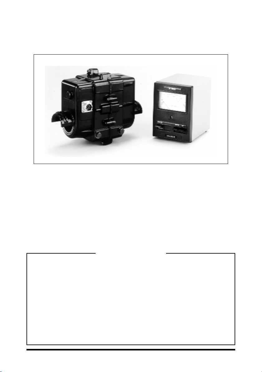
UNPACKING & INSPECTION
When unpacking the rotator confirm the presence of the following items;
Rotator Unit ......................................................................................... 1
Controller Unit .................................................................................... 1
7-pin Metal Connector ........................................................................ 1
Water Resist Cap ................................................................................. 1
Instruction Manual .............................................................................. 1
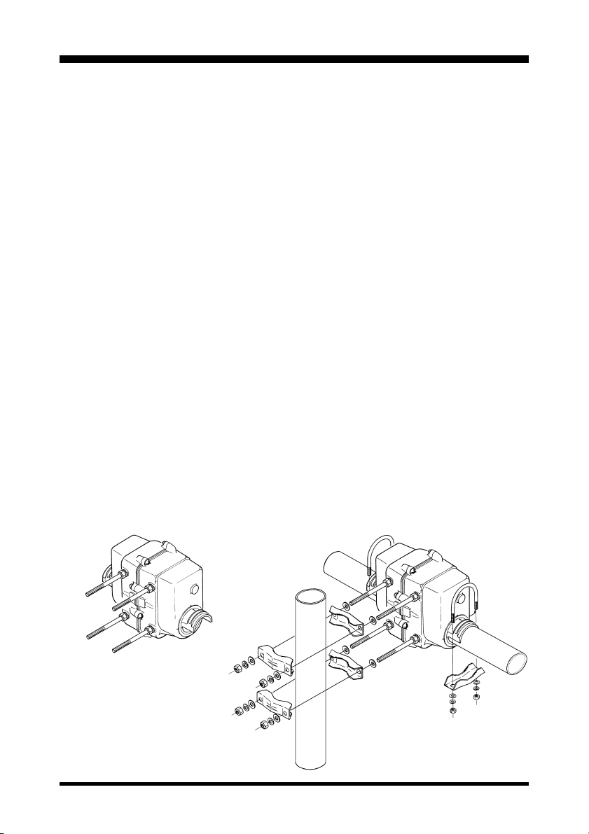
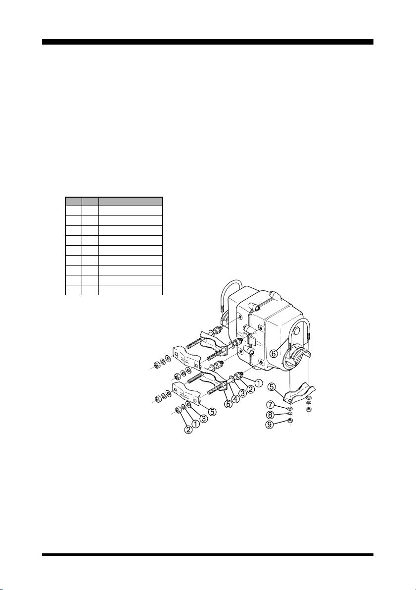
Plastic Bag containing;
8mm Spring washer ................................................................. 8
8mm Nut .................................................................................. 8
8mm Flat washer ..................................................................... 8
8mm dia Stud bolt ................................................................... 4
Pipe clamp ............................................................................... 6
U-Bolt ....................................................................................... 2
6mm Flat washer ..................................................................... 4
6mm Spring washer ................................................................. 4
6mm Nut .................................................................................. 4
Spare Fuse (117V;1A, 220V; 0.5A) ........................................ 1
If any of these items are missing or appear to be damaged, save the carton and pack-
ing material and notify the shipping company (or dealer, if purchased directly at his
shop).
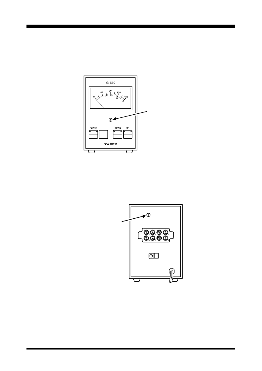
Before proceeding with installation, confirm that the AC voltage label on the rear of
the Controller matches your local line voltage: either “117V” for 110 to 120 VAC,
“220” for 220 to 240 VAC. If the labeled voltage range does not match, return the
controller to the dealer from whom you purchased it (different power transformers are
installed for the different voltage ranges).
Note that cable is not included with the rotator, as the length must be determined case-
by-case. Contact your Yaesu dealer to obtain the length of cable your installation
requires. For runs of over 100 feet, use #18 AWG instead of #20 AWG.

PAGE 3
G-550 INSTALLATION MANUAL
CONTROL CABLE PREPARATION & CONNECTION
1. Assemble the cable according to the following diagrams.
2. Connect each wire to the terminal on the rear panel of the controller, making sure
to match the numbers on the pins (terminals 7 and 8 are not used), and insert the
connector to the Jack on the rotator.
3. On the controller, make sure that the POWER switch is in the “OFF” position,
and connect the line cord to the AC power outlet.
4. Turn on the POWER switch. The meter lamp should light and the meter indicate
approximately 90° (center).
5. Press the UP switch. The rotator should turn as the meter indication moves to the
right. Release the UP switch and confirm that the rotator slowly stops.
6. Repeat step 5, pressing the DOWN switch instead of the UP switch. The rotator
should turn in the opposite direction as the meter indication moves to the left.
7. If operation does not occur as described above, check for a wiring error in the
cable connections. When everything checks out in the above steps, slide the water
resist cap over the connecter on the rotator. Remove the cable clamps from the
controller, clip them over the cables, and screw them back onto the controller.
Then replace the terminal cover.
Notes on Controller Operation:
HIf both UP and DOWN switches are pressed at the same time, the rotator turns
clockwise (up).
HRemember to turn the controller off when the rotator is not in use.
Make sure to insert the
Water Resist Cap first.
Tin the wire with solder.
Terminal 7 is not used.

PAGE 4
G-550 INSTALLATION MANUAL
ELEVATION INDICATOR CALIBRATION
Turn the controller off and note the position of the meter needle, which should be
precisely at the left edge of the scale. If not, adjust the zero adjust screw beneath the
meter face.
Press the UP switch to align the 180° markers on the rotator. The meter should now
point precisely to 180° (right edge of scale). If not, adjust the Full Scale ADJ poten-
tiometer on the rear panel so that it does.
0. ADJ Screw
Full Scale ADJ

PAGE 5
G-550 INSTALLATION MANUAL
ROTATOR INSTALLATION
The G-550 is designed to accommodate small- and medium-size antenna arrays. The
maximum safe load depends on the physical size of the antenna, method and quality
of mechanical installation, and maximum wind velocity at the installation site.
The diagrams below show several recommended installations. Notice that the pre-
ferred mounting method requires that each antenna be attached to the boom at its
center of gravity, with the boom there attached to the rotator at its center of gravity.
This minimizes stress on the rotator and supporting structure, especially during strong
winds.
1. Referring to Figure 1, screw one 8mm nut over the end of each stud bolt with the
shortest thread. Slip a spring washer over the threads, and screw each stud bolt
into holes in the side of the rotator.
2. Slip an 8mm flat washer over each installed stud bolt, and then the pipe clamps, as
shown in Figure 2. Place another flat washer and then spring washer over the end
of each stud bolt, and start a nut on each to hold the hardware in place.
3. Slide the boom through the rotator.
4. Place one U-bolt over each arm of the rotator, and assemble one pipe clamp, flat
washers, spring washers and nuts on the U-bolts as shown in Figure 2. Center the
boom carefully, and alternately tighten the nuts on each U-bolt 1/2-turn beyond
the point where the spring washers are flattened.
Figure 1
Figure 2

PAGE 6
G-550 INSTALLATION MANUAL
Be sure to leave enough slack in both the elevation control cable and the coaxial cable
feedline around the azimuth rotator so the antenna can rotate 180° without straining
the cable or feedline.
For dual parallel arrays, feedlines should be taped to the boom on either side of the
rotator, with enough slack left to allow 180° rotation without stressing the feedlines.
The rotator motors are rated for five-minutes intermittent duty. However, they be
brought to rest for at least 15 minutes afterwards.
No
Qty
8
8
8
4
6
2
4
4
4
Description
8φSpring Washer
8φNut
8φWasher
8φStud Bolt
Boom/Mast Clamp
U Bolt
6φWasher
6φSpring Washer
6φNut

PAGE 7
G-550 INSTALLATION MANUAL
G-550 Schematic Diagram

PAGE 8
G-550 INSTALLATION MANUAL
Note


Copyright 2001
VERTEX STANDARD CO., LTD.
All rights reserved
No portion of this manual
may be reproduced without
the permission of
VERTEX STANDARD CO., LTD.
Printed in Japan.
E12891001
Table of contents
Other Yaesu Controllers manuals
Popular Controllers manuals by other brands

HM Digital
HM Digital PS-202 user guide

Jung
Jung 1713DSTE operating instructions

Delta Electronics
Delta Electronics Programmable Logic Controller DVP-SA instruction sheet

Linear Technology
Linear Technology 1055 quick start guide

Brother
Brother LT-5100 user manual

Emerson
Emerson DIXELL XR77CHC Installation and operating instructions