SECTION 1 I
Limiting
Electrom.agnetic
Interference
Limiting Electromagnetic Interference (EMI)
This
equipment
has
been
tested
and
found
to
comply with
the
limits for a class Bdigi-
tal device,
pursuant
to
Part 15(8)
of
the
FCC
Rules. These limits
are
designed
to
provide
reasonable protection against a harmfUI interference in a residential installation. This
equipment
generates,
uses
and
can
radiate
radio frequency energy and,
if
not
installed
and
used in accordance with
the
instructions, may cause harmful interference
to
radio
communications. However, this does
not
guarantee
that
interference will
not
occur in
a particular installation.
If
this
equipment
does
cause harmful interference
to
radio
or
television reception, which
can
be
determined
by
turning
the
equipment
off
and
on,
the user
is
encouraged
to
try
to
correct
the
interference by
one
or
more
of
the
follow-
ing measures:
• Reorient
or
relocate
the
receiving
antenna
• Increase
the
separation
between
the
equipment
and
receiver
• Connect
the
equipment
into
an
outlet
on
a circuit different from
that
to
which
the
receiver
is
connected
• Consult
the
dealer
or
an
~xperienced
radio I
TV
technician for help
SECTION 8 I
Switching
Power
Supplies
&
RF
Noise
1.
Switched
mode
power
supplies
(SMPS)
employ high frequency switching
and
thus,
are
a source
of
radio interference, a recipient of radio interference
and
a conduit
of
radio interference. (Older linear type trans-former based
power
supplies
do
not
em-
ploy high frequency switching volt-ages
and
will
be
quieter
as compared
to
switch-
ing
type
of
supplies).
2. The primary emission sources originate
in
the
switching devices
due
to
their fast
switching current transitions: harmonics
of
the
switching frequency
and
broadband
noise
created
by
under-damped
oscillations in
the
switching circuit. The secondary
source is from
the
bridge rectifier,
both
rectifier noise
and
diode recovery. The
AC
input rectifier I capacitor
in
the
front
end
of
the
switching power supplies (excepting
those
with
power
factor correction) are notorious for
generating
power
supply har-
monics
due
to
the
non
linear input current waveform. The noise
is
both
conducted
and
radiated
through
the
input power cord
and
the
DC
output
wiring
to
the
radio.
3.
Switching
power
supplies are also recipients
of
radio interference. The normal
operation
of
the
power supply can
be
disturbed
due
to
RF
noise
getting
coupled
into
the
power
supply. Thus,
the
power supply may
generate
excessive
RF
noise
and
lose
output
voltage regulation
due
to
excessive transmitter energy being coupled
through
the
AC
I
DC
lines
to
the
power supply's regulator feedback path.
This
may
be
due
to
antenna
being
too
close
or
due
to
the
antenna
or
feed
system not radiat-
ing properly.
First
check
the
antenna
system
SWR.
Then.
if
necessary, relocate
either
the
antenna
or
the
power supply farther apart.
SECTION 8 I
Switching
Power
Supplies
&
RF
Noise
4. The receiver may
"hear"
the
power supply. A slowly moving, slightly buzzing carrier
heard
in
the
receiver may
be
caused
by
the
antenna
being
too
close.
As
with
the
transmitter
related
noise pick up, a loose coaxial connector
or
a broken
or
a
miss-
ing
ground
may
aggravate
this problem. Normally
these
noises
will
be
below
the
background
or
"band"
noise. Increase
the
separation
between
the
power supply
and
the
receiving
antenna.
Use
an
outdoor
antenna.
This
will
reduce
the
amount
of signal
picked
up
from
the
power
supply
and
also increase
the
amount
of
the
desired signal.
5.
The
conducted
and
radiated noises
are
limited as
per
the
applicable national I inter-
national standards.
In
North America,
the
applicable
standard
is
as per
FCC
Part 15(8)
for Class "B" digital devices. The European
standard
is
as per
ENS5022,
Class
"B" &
EN610000-3-2,
3.
Thus,
the
RF
interference
is
limited
but
not
entirely eliminated.
6.
The
conducted
RF
noise from
these
power supplies
is
limited
to
the
maximum allow-
able
levels by internal filtration. The filtered
RF
noise currents (normally <
SmA)
are
bypassed
to
the
chassis
of
the
power
supply. The chassis
is,
in
turn
connected
to
the
earth
ground
pin of
the
AC
input
power
cord (for
Class
1 units). Thus,
the
filtered
noise currents
are
intentionally leaked
to
the
earth
ground. This
is
termed
as
the
"Earth
leakage
Currenr.
For
safety against electric shock, this
earth
leakage current
is
also required
to
be
limited.
It
will
be
seen
that
these
two
requirements are conflict-
ing.
NOTE:
In
some
cases.
to
prevent electric shock hazard
due
to
abnormal leakage current
(like in marinas, spas,
hot
tubs,
wet
spaces etc.),
the
AC
outlet
circuits I receptacles
in
these
areas
are
served
through
a
GFCI
(Ground Fault Circuit Interrupter).
This
GFCI
is
normally
set
to
trip
when
it senses
an
earth
leakage current > 5
mA.
A single
GFCI
may
be
serving multiple
AC
outlet
circuits I receptacles
and
therefore,
will
be
sensing
the
sum
of
all
the
leakage currents
of
the
devices connected
to
these.
As
the
switching power
supplies have intentional leakage current as explained above, it may trip a
GFCI
feeding
multiple
AC
outlet
circuits I receptacles.
In
such cases, disconnect devices connected
to
the
other
AC
outlet
circuits I receptacles served
by
this
GFCI.
7.
Following additional guidelines may
be
followed
to
reduce
the
effects of
RF
noise:
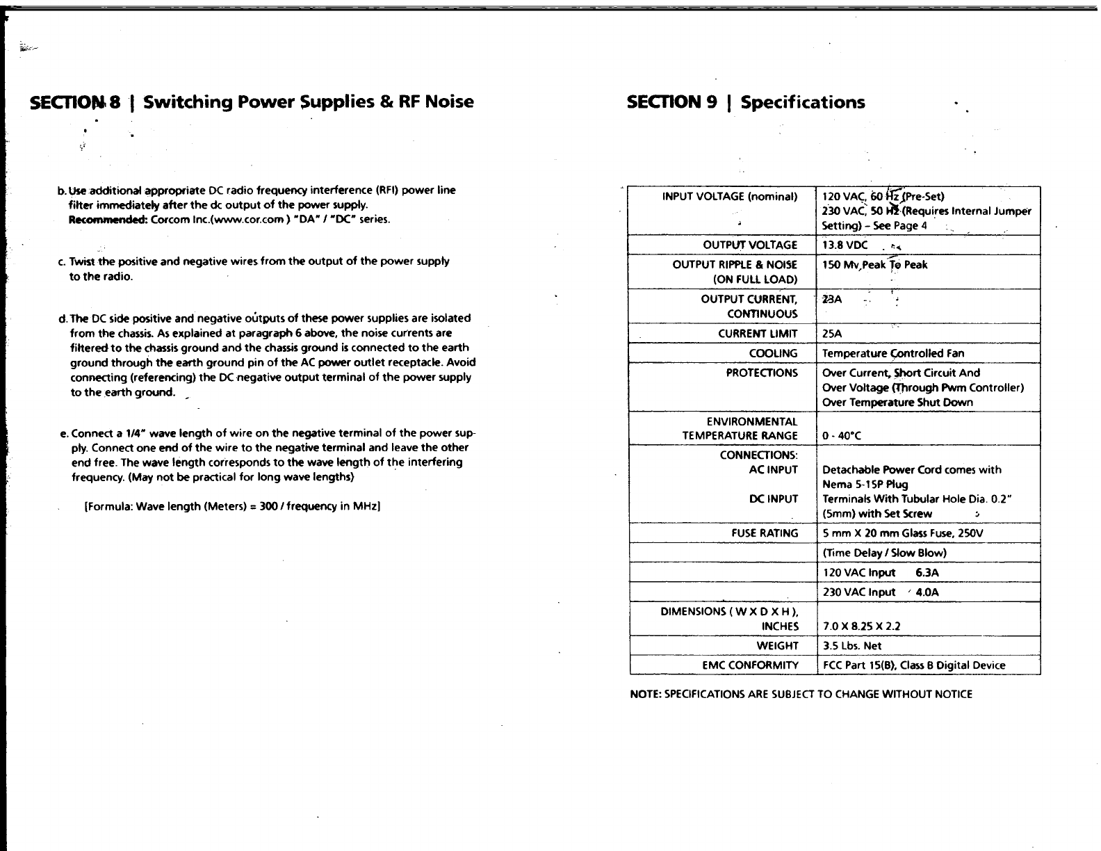
a.
Use
additional appropriate
AC
radio frequency interference
(RFI)
power
line filter
immediately
before
the
ac input of
the
power supply.
Recommended: Corcom
Inc.
( www.cor.com )
"Q"
series. Filtered, ferrite coated
cord
set
(www.emceu-pen.com)
is
another
choice. These cord sets, with integral
line interference filters, reduce common
and
differential
mode
interferences over
a wide frequency range. Because they are shielded, they are also effective against
radiated interferences.
In
addition
to
the
built-in filter networks.
the
cable conduc-
tors are
coated
with
an
RF
absorbing ferrite compound.
This
provides additional
attenuation
at
high frequencies
that
is
lacking
in
most regular
LC
filters. The
RF
absorption of
the
ferrite-coated cable avoids resonance's
at
high frequencies,
reducing
the
conducted
and
radiated
RF
noises even further.