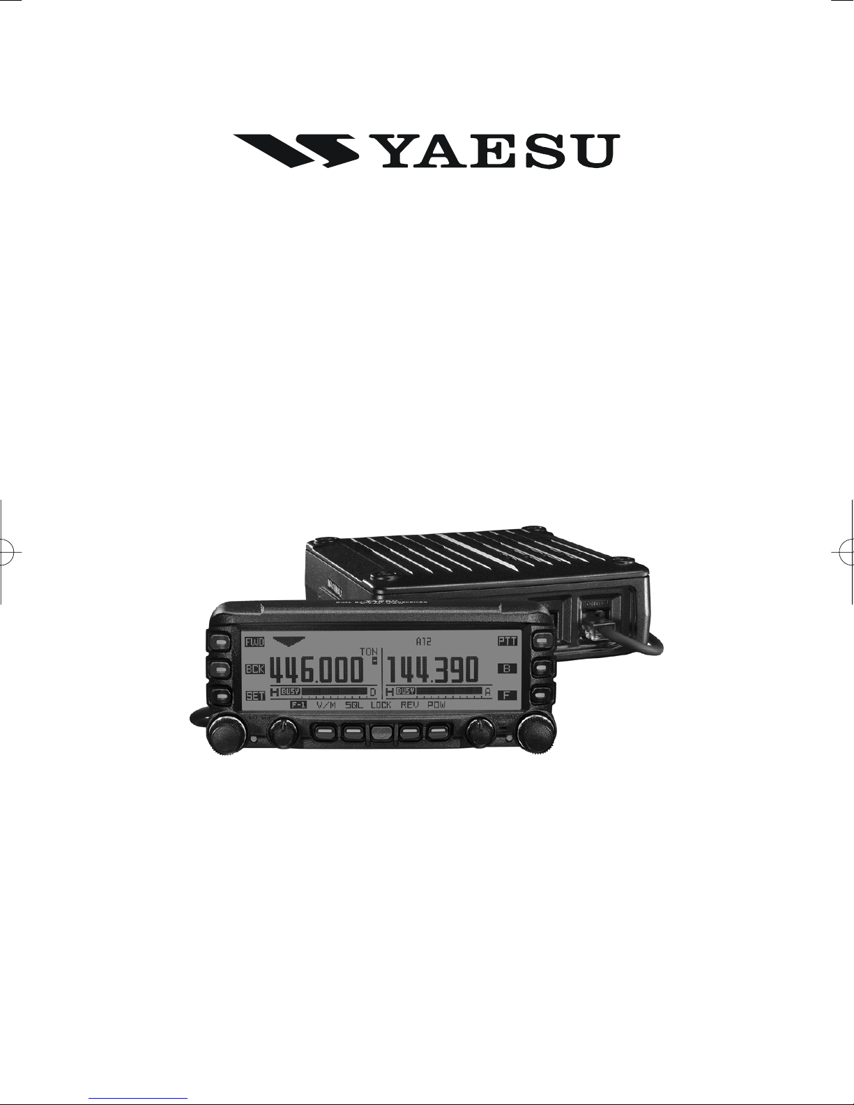
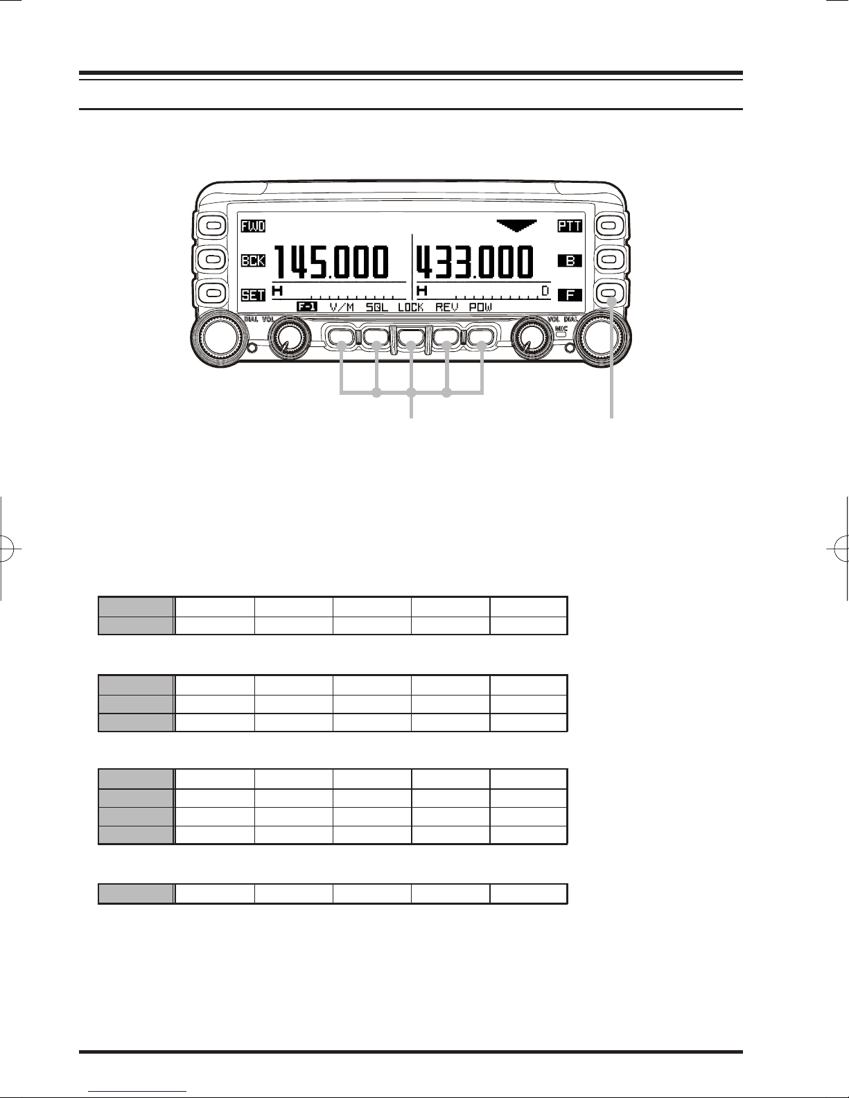
Yaesu FTM-350R - APRS User manual

DUAL BAND FM TRANSCEIVER
FTM-350R
OPERATING MANUAL
VERTEX STANDARD CO., LTD.
4-8-8 Nakameguro, Meguro-Ku, Tokyo 153-8644, Japan
VERTEX STANDARD
US Headquarters
10900 Walker Street, Cypress, CA 90630, U.S.A.
YAESU UK LTD.
Unit 12, Sun Valley Business Park, Winnall Close
Winchester, Hampshire, SO23 0LB, U.K.
VERTEX STANDARD HK LTD.
Unit 5, 20/F., Seaview Centre, 139-141 Hoi Bun Road,
Kwun Tong, Kowloon, Hong Kong
VERTEX STANDARD (AUSTRALIA)PTY., LTD.
Normanby Business Park, Unit 14/45 Normanby Road
Notting Hill 3168, Victoria, Australia

Contents
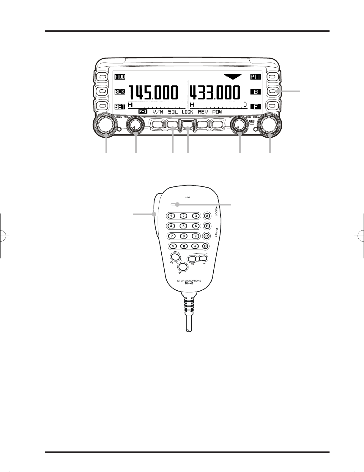
Front Panel Controls & Switches .......................... 1
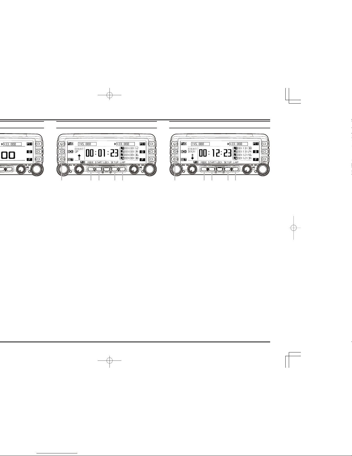
Timer Page Operation ............................................ 2
Radio Page Basic Operation .................................. 3
[SMART FUNCTION]Key ................................... 4
General ................................................................. 4
[SMART FUNCTION]Key Command Details ... 5
Memory Operation ................................................. 6
Memory Storage ................................................... 6
Storing Independent Transmit Frequency ............ 7
Memory Recall ..................................................... 8
Memory Edit ........................................................ 9
Labeling Memories .......................................... 9
Copying Memories ........................................... 9
Deleting Memories ........................................... 9
Memory Channel Sort ........................................ 10
AF Dual Operation ............................................... 11
Band Scope Operation ......................................... 12
General ............................................................... 12
Enhnced Mode ................................................... 13
CTCSS/DCS/EPCS Operation ............................ 14
CTCSS Operation ............................................... 14
DCS Operation ................................................... 14
EPCS Operation ................................................. 15
Scan Operation ..................................................... 16
VFO Scan ........................................................... 16
Memory Scan ..................................................... 16
Programmable Memory Scan (PMS)................. 17
Priority Channel Scan (Dual Watch).................. 17
Bluetooth®Operation ......................................... 18
Pairing ................................................................ 18
Operation ............................................................ 19
Internet Connection Feature ............................... 20
SRG (“Sister Radio Group”)Mode .................... 22
FRG (“Friendly Radio Group”)Mode ............... 21
DTMF Operation .................................................. 22
Manual DTMF Tone Generation ........................ 22
DTMF Autodialer ............................................... 22
Baro/Alti Page Operation .................................... 23
GPS Operation ...................................................... 24
Navi Operation ..................................................... 26
Audio Playback Operation .................................. 28
Miscellaneous Setting (Set Mode Operation)..... 30
AUDIO Group .................................................... 31
TX/RX Group ..................................................... 33
DISPLAY Group ................................................ 35
MEMORY Group ............................................... 36
SCAN Group ...................................................... 37
SYSTEM Group ................................................. 38
NAVI Group ....................................................... 40
TIMER/CLOCK Group ...................................... 41
SIGNALING Group ........................................... 42
OPTION Group .................................................. 44
Special Function Menu ........................................ 46
Cloning .................................................................. 47
Installation ............................................................ 48
Preliminary Inspection ....................................... 48
Installation Tips .................................................. 48
Safety Information .............................................. 49
Specification .......................................................... 50
Accessories & Options .......................................... 51
Supplied Accessories ......................................... 52
Optional Accessories .......................................... 52
RESET PROCEDURE
When key functions are lost, or erratic operation is encountered, you may clear all
settings of the transceiver and set them to the factory default with the following
procedures:
1. Turn the radio “off”.
2. Press and hold in the key located to the left of the [POWER]switch while
turning the radio on, to enter the “Special Function” mode.
3. Rotate the left side [DIAL]knob to select “6 ALL RESET”.
4. Press the left side [DIAL]knob and confirm that (OK? [SET]) is displayed on
the LCD.
5. Press the left side [DIAL]knob once more to complete the reset procedure.

FTM-350R OPERATING MANUAL 1
FRONT PANEL CONTROLS & SWITCHES
[PTT]KEY
Press this key to transmit.
[SET](SET MODE)KEY
Press this key to access the Set Mode.
[F](FUNCTION)KEY
Press this key to change the current functions of the
[SMART FUNCTION]keys.
[DIAL]KNOB
Rotate this knob to select the operating frequency
(or memory channel) of the right side receiver.
Press and hold this knob for one second to enable
to tuning the VFO frequency in 1 MHz step.
When the right side receiver is set to “Main” band,
press this knob briefly to activates the Band Scorp
feature.
When the right side receiver is set to “Sub” band,
press this knob briefly to change the right side
receiver to “Main” band.
[SMART FUNCTION]KEY
These four keys select many of the most important
operating features of the transceiver.
When changing the operating function page or press-
ing the [FUNCTION]key, the current function of
these key will change and appear above each keys.
[DIAL]KNOB
Rotate this knob to select the operating frequency
(or memory channel) of the left side receiver.
Press and hold this knob for one second to enable
to tuning the VFO frequency in 1 MHz step.
When the left side receiver is set to “Main” band,
press this knob briefly to activates the Band Scorp
feature.
When the leftside receiver is set to “Sub” band,
press this knob briefly to change the left side re-
ceiver to “Main” band.
MICROPHONE
[B](BAND)KEY
Press this key to change the operating band of the
Main band.
Available bands are:
Left Band: AM Radio, FM Radio, 144 MHz Band,
430 MHz Band, and Audio Line-In
Right Band: 144 MHz Band and 430 MHz band
You may assign the other function to this key. See
page 36.
[VOL]KNOB
Adjusts the right
side receiver’s
audio volume.
[VOL]KNOB
Adjusts the left
side receiver’s
audio volume.
[POWER]SWICTH
Press and hold this key for two sec-
onds to toggle the transceiver’s
power on and off.
Press this key briefly while the
transceiver is turned on to toggle the
key lockout feature on or off.
[FWD]/[BCK](PAGE)KEY
Press these keys briefly to select the operating func-
tion pages.
The available pages are: “Radio” page, “Timer” page,
“Baro/Alti” page, “Navigation” page, and “GPS
Status” page.
:Requires optional “FGPS-1” GPS Unit.
Press and hold in these keys toggle the Dual Receive
feature “on” and “off”.

FTM-350R OPERATING MANUAL2
TIMER PAGE OPERATION
1Press the [FWD]or [BCK]key repeatedly, until the
“Timer Page” appears.
2Press the [MODE]key repeatedly, until the “Clock” ap-
pears.
To return to the “Radio” page, press the [FWD]or [BCK]
key repeatedly, until the “Radio” Page appears.
The FTM-350’s clock is setup from the Set mode item “I01
DATA&TIME ADJUST” in the “TIMER/CLOCK” group.
See page 39 for details.
2
1Press the [FWD]or [BCK]key repeatedly, until the
“Timer Page” appears.
2Press the [MODE]key repeatedly, until the “Count Up”
timer appears.
The “Count Up” timer has two kinds: which is with Lap
function and without Lap function.
3Press the [SETUP]key to set the interval time of the
timer beep: rotate the [DIAL]knob to select the interval
time, then press the [SETUP]key.
4Press the [START]key to initiate the “Count Up” timer.
5Press the [LAP]key to save the lap time, if desired (up to
four laps).
6Press the [STOP]key to stop the “Count Up” timer.
7Press and hold the [START]key for two seconds to reset
the “Count Up” timer.
When the optional GPS antenna is connected, the average
speed, or the maximum speed of your vehicle may be dis-
played instead of the lap function, by pressing the [MODE]
key again. Press the [DISP]key to switch between average
and maximum speed.
To return to the “Radio” page, press the [FWD]or [BCK]
key repeatedly, until the “Radio” Page appears.
2 4
6
3 5
1Press the [FWD]or [BCK]key repeatedly, until the
“Timer Page” appears.
2Press the [MODE]key repeatedly, until the “Count
Down” timer appears.
The “Count Down” timer has two kinds: which is with
Lap function and without Lap function.
3Press the [SETUP]key to set the setup time: rotate the
[DIAL]knob to select the setup time, then press the
[SETUP]key.
4Press the [START]key to initiate the “Count Down”
timer.
5Press the [LAP]key to save the lap time, if desired (up to
four laps).
6Press the [STOP]key to stop the “Count Down” timer.
7Press and hold the [START]key for two seconds to reset
the “Count Down” timer.
When the optional GPS antenna is connected, the average
speed, or the maximum speed of your vehicle may be dis-
played instead of the lap function, by pressing the [MODE]
key again. Press the [DISP]key to switch between average
and maximum speed.
To return to the “Radio” page, press the [FWD]or [BCK]
key repeatedly, until the “Radio” Page appears.
2 4
6
7
3 5
“CLOCK” “COUNT UP”TIMER “COUNT DOWN”TIMER
1 1 1

FTM-350R OPERATING MANUAL 3
RADIO PAGE BASIC OPERATION
1Press and hold the [POWER]key for two seconds to turn the transceiver on.
2Rotate the [VOL]knob to adjust the audio volume level.
3Press the [SQL]key briefly then rotate the [DIAL]knob carefully to adjust the squelch
threshold level.
4Press the [DIAL]knob briefly to set the “Main” band.
5Press the [B]key to select the operating band of the “Main” band.
6Rotate the [DIAL]knob to select the operating frequency.
7Press and hold the [PTT]key, and speak into the microphone in a normal voice level.
8Press and hold the [POWER]key for two seconds to turn the transceiver off.
3 1
8
2 4
6
The basic operations are listed numerically in the illustration below.
6 2
7
MICROPHONE
5

FTM-350R OPERATING MANUAL4
[SMART FUNCTION]KEY
The FTM-350 operations are performed using the [SMART FUNCTION]keys. The vari-
ous functions of the keys are changed by pressing the [F]key.
[SMART FUNCTION]key [FUNCTION]key
Pressing the [F]key repeatedly will change the function command of each [SMART FUNC-
TION]key as shown in the following tables. It is easy to recall and perform a desired
operation. The current function of each key is shown in the display above the key button.
F-1F-1
F-1F-1
F-1 V/M SQL LOCK REV POW
F-2F-2
F-2F-2
F-2 SCAN DW LOCK SKIP1AD-F2
F-1F-1
F-1F-1
F-1 V/M SQL LOCK REV POW
F-2F-2
F-2F-2
F-2 SCAN DW LOCK SKIP1AF-D2
F-3F-3
F-3F-3
F-3 zREC X CLR LOCK XPLAY VOICE
F-1F-1
F-1F-1
F-1 V/M SQL LOCK REV POW
F-2F-2
F-2F-2
F-2 SCAN DW LOCK SKIP1AF-D2
F-3F-3
F-3F-3
F-3 SyLIST MSG LOCK BCON B-TX
F-4F-4
F-4F-4
F-4 zREC X CLR LOCK XPLAY VOICE
SQLSQL
SQLSQL
SQL TYPE TyFRQ LOCK DyCOD PyFRQ
Default
When the optional Voice Guide Unit is installed.
When the optional Voice Guide Unit is installed and the APRS feature is activated.
Press and hold the [F]key for two seconds.
1: The [SKIP]command appears only in memory mode.
2: You may change the [AD-F]command to another command with Set Mode item “G05 F KEY”. See
page 38.
GENERAL

FTM-350R OPERATING MANUAL 5
[SMART FUNCTION]KEY
V/M
SQL
LOCK
REV
POW
Press Key
Press & Hold Key
Press Key
Press & Hold Key
Press Key
Press & Hold Key
Press Key
Press & Hold Key
Press Key
Press & Hold Key
Switches frequency control betwen the “VFO” and “Memory System”.
Activates the “Memory Write” mode (for memory channel storage).
Activates the Squelch threshold level.
No Action.
Toggles the key lockout feature “on and “off”.
Toggles the transceiver power “on and “off”.
Reverses transmit and receive frequencies while working through a repeater.
No Action.
Selects the desired transmit power output level (“LOW”, “MID”, and “HIGH”)
No Action
F-1
SCAN
DW
LOCK
SKIP
AD-F
Press Key
Press & Hold Key
Press Key
Press & Hold Key
Press Key
Press & Hold Key
Press Key
Press & Hold Key
Press Key
Press & Hold Key
Activates the Scanner.
No Action.
Activates the Dual Watch feature.
No Action.
Toggles the key lockout feature “on and “off”.
Toggles the transceiver power “on and “off”.
Selects the “scan flag” to the current memory channel.
No Action.
Activates the AF Dual function.
No Action.
F-2
SyLIST
MSG
LOCK
BCON
B-TX
Press Key
Press & Hold Key
Press Key
Press & Hold Key
Press Key
Press & Hold Key
Press Key
Press & Hold Key
Press Key
Press & Hold Key
Opens the “Station List” window.
No Action.
Opens the “Message List” window.
No Action.
Toggles the key lockout feature “on and “off”.
Toggles the transceiver power “on and “off”.
Changes the APRS beacon: ON, OFF or AUTO.
No Action.
Transmits the APRS beacon.
No Action.
F-3
zREC
X CLR
LOCK
XPLAY
VOICE
Press Key
Press & Hold Key
Press Key
Press & Hold Key
Press Key
Press & Hold Key
Press Key
Press & Hold Key
Press Key
Press & Hold Key
Initiates the recording of the incoming receiver audio.
No Action.
Clears the recording data.
No Action.
Toggles the key lockout feature “on and “off”.
Toggles the transceiver power “on and “off”.
Plays back the recorded data.
Selects the Voice Memory Register (slot 1 - 8, or ALL).
Announces the operating frequency of the “Main” band.
No Action.
F-4
[SMART FUNCTION]KEY COMMAND DETAILS
TYPE
TyFRQ
LOCK
DyCOD
PyFRQ
Press Key
Press & Hold Key
Press Key
Press & Hold Key
Press Key
Press & Hold Key
Press Key
Press & Hold Key
Press Key
Press & Hold Key
Selects the Squelch type.
No Action.
Selects the CTCSS Tone frequency.
No Action.
Toggles the key lockout feature “on and “off”.
Toggles the transceiver power “on and “off”.
Selects the DCS code.
No Action.
Selects the User Programmed Reverse CTCSS Tone frequency..
No Action.
SQL

FTM-350R OPERATING MANUAL6
MEMORY OPERATION
MEMORY STORAGE
Before beginning the Memory Storage operation, select the desired frequency while oper-
ating in the “Main” band VFO. Be sure to set up any desired CTCSS or DCS tones, as well
as any repeater offset. The power level setting is also stored in the memory.
1Press and hold in the [V/M]key for two seconds to display the “Memory Edit” window.
2If you wish to append an Alpha/numeric “Tag” to this channel, press and hold the
[V/M]key again. Then enter the desired name “Tag” (up to 8 characters) one of the
methods shown in the following examples. Otherwise, skip to the next step.
Example 1: Enter the characters/numbers by pressing the microphone keypad buttons;
or use the microphone [UP]/[DWN]keys to select them. Press the [B]
key to move the cursor to the next digit. Press the [A]key to backspace the
cursor, and press the [C]key to delete all data after the cursor. You may
change the character (uppercase, lowercase, numeric, or symbol) by press-
ing the []key.
Example 2: Rotate the left side [DIAL]knob to select a character/number and press
the []key to move the cursor to the next digit. Press the [BS]key to
backspace the cursor. You may change the character (capital, small, nu-
meric, or symbol) by pressing the [FONT]key.
1
2
3
2
222
Impotant Note
On rare occasions the stored data may become corrupted by miss operation, or
static electricity. When repairs are made, the memory data may be lost. Please
write down or record the memory information so you will be able to restore it if
needed.

FTM-350R OPERATING MANUAL 7
STORING INDEPENDENT TRANSMIT FREQUENCY (“ODD SPLIT”)
3Press the the [V/M]key to store the frequency and settings into memory.
All memories can store an independent transmit frequency, for operation on repeaters with
non-standard shift.
To store the “Odd Split” transmit frequency, first store the receive frequency using the
1
2 3
MEMORY OPERATION
method already described on the previous page. Then follow the below procedures:
1Tune the desired transmit frequncy on the “Main” band, then press and hold in the
[V/M]key for two seconds.
2Rotate the left side [DIAL]knob to select the same memory channel number as used in
step 1 above.
3Press the [TXIN]key to store the independent transmit frequency into memory.

FTM-350R OPERATING MANUAL8
MEMORY OPERATION
MEMORY RECALL
1Press the [V/M]key, to set the “Main” band to the memory mode.
2Rotate the [DIAL]knob to select the desired memory channel.
3To return to the VFO mode, press the [V/M]key.
When the radio in the memory mode, you may recall the memories to the “Main” band
by entering the memory number useing the microphone keypad.
For example, to recall the memory channel #14, press [0]Æ[1]Æ[4].
When an “Odd Split” memory channel is recalled, the “ ” indication will appear in
the display.
When a “Tagged” memory channel is displayed with the Alpha/numeric “Tag”, a small
frequency indication will also be shown. You may change the display between “Tag”
indication and “Frequency” indication via Set Mode item “D018 MEMORY DIS-
PLAY” in the “MEMORY” group.
1
3
2

FTM-350R OPERATING MANUAL 9
MEMORY OPERATION
MEMORY EDIT
The memory channels may be edited using Set Mode item “D02 MEMORY EDIIT” in the
“MEMORY” group.
LABELING MEMORIES
1. Rotate the left side [DIAL]knob to select a memory channel to append or change the
label.
2. Press the [V/M]key for two seconds, and then add or change the label in the same
manner as step 2of the “Memory Storage” procedure (see page 6).
COPYING MEMORIES
1. Rotate the left side [DIAL]knob to select the memory channel to be copied.
2. Press the [SEL]key. The selected column will blink.
3. Rotate the left side [DIAL]knob to select a memory channel to store the data.
4. Press the [CPY]key to copy the memory channel data.
5. Press the [SEL]key to save the data and stop the column blinking.
DELETING MEMORIES
1. Rotate the left side [DIAL]knob to select the memory channel to delete.
2. Press the [SEL]key. The selected column will blink.
3. Press the [DEL]key to delete the memory channel data.

FTM-350R OPERATING MANUAL10
MEMORY CHANNEL SORT
The memory channels may be sorted and renumbered by frequency, from low to high using
the “Special Function” mode.
1. Turn the radio off.
2. To enter the “Special Function” mode, turn the radio on while press and holding the
key located at the left of the [POWER]switch.
3. To sort the memory channels in the left band, rotate the left side [DIAL]knob to select
function menu item “3 L-MEMORY SORT”. To sort the memory channels in the
right band, rotate the left side [DIAL]knob to select function menu item “4 R-
MEMORY SORT”.
4. Press the left side [DIAL]knob, to display the confirmation message “OK? [SET]” on
the display. If you decide to cancel the memory channel sort, press the [ESC]key.
5. Press the left side [DIAL]knob again. After several seconds, sorting is complete, and
the FTM-350 will reset automatically.
MEMORY OPERATION

FTM-350R OPERATING MANUAL 11
AF DUAL OPERATION
The AF Dual function permits monitoring an amateur band frequency while listening to an
FM broadcast station.
1Press the [F]key repeatedly, until the [SMART FUNCTION]keys change to the
“F-2” mode.
2Press the [AD-F]key to activate the AF Dual function.
The left side receiver switches to FM Broadcast. The right side receiver will monitor
the amateur frequencies, while you listen to the FM Broadcast station.
3Rotate the left side [DIAL]knob to tune the desired FM broadcast stations.
4To change the audio source to the AM Broadcast band, or Line-In audio, press and hold
the [AD-F]key for two seconds to access the Set Mode. Select the desired audio source
by rotating the left side [DIAL]knob, and then press the [ESC]key.
5When a signal is received in the amateur band, the amateur band audio is output to the
speaker. The FM or AM broadcast station will no longer be heard.
6When the right side receiver is set in the amateur band by “Main” band, you may
transmit on the amateur band by pressing the [PTT]key.
7Press the [AD-F]key to disable the AF Dual function and return to normal operation.
3
6
1
2
4
7

FTM-350R OPERATING MANUAL12
BAND SCOPE OPERATION
GENERAL
The Band Scope permits viewing operating activity on channels above and below the cur-
rent operating channel, in the VFO mode.
1Press the “Main” band [DIAL]knob to activate the Band Scope.
2Press the [BW]key to toggle the visible bandwidth to “±22 channels” and “±50 chan-
nels”.
3Press the [ATT]key to reduce the receiving signal by approximately 10 dB, if desired
(except the AM and FM Broadcast bands).
4Press the [STOP]key to stop the sweep of the Band Scope temporarily, if desired.
Press the [START]key to start the sweep of the Band Scope again.
5Press the “main” band [DIAL]knob to disable the Band Scope and return to normal
operation.
21
5
34

FTM-350R OPERATING MANUAL 13
BAND SCOPE OPERATION
ENHANCED MODE
When in Mono-Band mode, the Enhanced Band Scope “Special Function” features may
be activated. (See “Switching to the Enhanced Mode” below).
Switching to the Enhanced Mode
1. Turn the radio off.
2. Turn the radio on while holding the key, which is located left of the [POWER]
switch, to enter the “Special Function” mode.
3. Rotate the left side [DIAL]knob to select the function menu item “8 BAND
SCOPE”.
4. Press the left side [DIAL]knob, and then rotate the left side [DIAL]knob to
select “SPECIAL”.
5. Press the left side [DIAL]knob to save the new setting.
6. Press the [ESC]key, the FTM-350R is reset automatically.
1Rotate the “Main” band [DIAL]knob to tune the operating frequency.
2Rotate the “Sub” band [DIAL]knob to move the cursor (S).
3Press the [C=CSR]key to return the cursor to band center.
4Press the [SCSR]key, to change the “S” cursor to “U”. In this case, you may tune
the operating frequency by moving cursor, or by rotating the “Sub” band [DIAL]knob.
5Press the [C=CSR]key to return to the current frequency, and the cursor to band
center, and change the “U” cursor to “S”.
1
4
3
5
2

FTM-350R OPERATING MANUAL14
CTCSS/DCS/EPCS OPERATION
CTCSS OPERATION
1. Press and hold in the [F]key for two seconds to change the [SMART FUNCTION]
key category to the “SQL” functions.
2. Press the [TYPE]key repeatedly, until the “TONE SQL” notation appears; this acti-
vates the CTCSS operation.
3. Press the [TyFRQ]key, then rotate the “Main” band’s [DIAL]knob to select the de-
sired CTCSS frequency.
4. Press the [ESC]key to save the new setting and exit to normal operation.
5. To end the CTCSS operation, press the [TYPE]key repeatedly, until the “OFF” nota-
tion appears.
You may customize the CTCSS operation so that a ringing “bell” sound alerts you when a
call is coming in. Use Set Mode item “J01 BELL RINGER” in the “SIGNALING” group.
See page 42 for details.
DCS OPERATION
1. Press and hold in the [F]key for two seconds to change the [SMART FUNCTION]
key category to the “SQL” functions.
2. Press the [TYPE]key repeatedly, until the “DCS” notation appears; this activates the
DCS operation.
3. Press the [DyCOD]key, then rotate the “Main” band’s [DIAL]knob to select the de-
sired DCS code.
4. Press the [ESC]key to save the new setting and exit to normal operation.
5. To end the DCS operation, press the [TYPE]key repeatedly, until the “OFF” notation
appears.
You may customize the DCS operation so that a ringing “bell” sound alerts you when a call
is coming in. Use Set Mode item “J01 BELL RINGER” in the “SIGNALING” group.
See page 42 for details.

FTM-350R OPERATING MANUAL 15
CTCSS/DCS/EPCS OPERATION
EPCS OPERATION
The EPCS (Enhanced Paging & Code Squelch) feature allows addressing calls to a specific
station (Paging), and choosing to receive only the calls directed to your station (Code
Squelch).
The EPCS feature use two pairs of (alternately switched) CTCSS tones, which are stored in
the pager memories. The receiver remains silent until it receives the CTCSS tone pair that
matches those stored in the receiving pager memory.
1. Store the CTCSS tone pairs using Set Mode item “J04 PAGER CODE” in the “SIG-
NALING” group. The Sub menus “1: RX” and “2: RX” set the receiving tone codes,
and Sub menus “3: TX” and “4:TX” set the transmit tone codes.
2. Press and hold in the [F]key for two seconds to change the [SMART FUNCTION]
key category to the “SQL” functions.
3. Press the [TYPE]key repeatedly, until the “PAGER” notation appears; this activates
the EPCS feature.
4. To end the EPCS operation, press the [TYPE]key repeatedly, until the “OFF” notation
appears.
You may customize the EPCS operation so that a ringing “bell” sound alerts you when a
EPCS call is received. Use Set Mode item “J01 BELL RINGER” in the “SIGNALING”
group. See page 42 for details.

FTM-350R OPERATING MANUAL16
VFO SCAN
1. Press the [F]key repeatedly until the [SMART FUNCTION]keys “F-1” category is
displayed. Then, if necessary, set the “Main” band to VFO mode by pressing the [V/M]
key on the “F-1” category.
2. Press the [F]key briefly to change the [SMART FUNCTION]keys to the “F-2” cat-
egory.
3. Press the [SCAN]key on the “F-2” category to initiate the VFO scan.
4. Press the [SCAN]key again to stop the VFO scan.
You may customize the functions of the VFO Scan using the following Set Mode items:
“F02 SCAN DIRECTION”, “F03 SCAN RESUME”, “F04 SCAN STOP BEEP” in the
“SCAN” group and “G08 RX COVERAGE” in the “SYSTEM” group.
MEMORY SCAN
1. Press the [F]key repeatedly until the [SMART FUNCTION]keys change to the “F-1”
category, Then, if necessary, set the “Main” band to memory mode by pressing the
[V/M]key.
2. Press the [F]key briefly to change the [SMART FUNCTION]key category to “F-2”.
3. Press the [SCAN]key on the “F-2” category to initiate the memory scan.
4. Press the [SCAN]key again to stop the memory scan.
You may customize the functions of the Memory Scan using Set Mode items “D03
MEMORY SCAN TYPE” in the “MEMORY” group, “D04 MEMORY SKIP/SELCT”,
“F03 SCAN RESUME”, “F04 SCAN STOP BEEP” in the “SCAN” group, and “G08 RX
COVERAGE” in the “SYSTEM” group.
SCAN OPERATION

FTM-350R OPERATING MANUAL 17
PROGRAMMABLE MEMORY SCAN (PMS)
This feature allows scanning with sub-band limits.
1. Store the lower sub-band limit into the memory channel “P1L”.
2. Store the upper sub-band limit into the memory channel “P1U”.
3. Set the “Main” band to memory mode, if necessary, by pressing the [V/M]key on the
“F-1” category.
4. Recall memory channel “P1L” or “P1U”.
5. Press the [F]key briefly to change the [SMART FUNCTION]keys to the “F-2” cat-
egory.
6. Press the [SCAN]key on the “F-2” category to initiate the scanning within the pro-
grammed range.
7. Press the [SCAN]key again to stop the scanner.
8. Press the [V/M]key on the “F-1” category to change between the memory mode and
the VFO mode.
9. Nine pairs of band limit memories, labeled “P1L/P1U” through “P9L/P9U” are avail-
able. Upper and lower operation limits may be set on a number of bands.
You may customize the functions of the Memory Scan via Set Mode items “D03 MEMORY
SCAN TYPE” in the “MEMORY” group, “D04 MEMORY SKIP/SELCT”, “F03 SCAN
RESUME”, “F04 SCAN STOP BEEP” in the “SCAN” group, and “G08 RX COVER-
AGE” in the “SYSTEM” group.
PRIORITY CHANNEL SCAN (DUAL WATCH)
This feature is a two-channel scanning function, which allows operation on a VFO or Memory
channel, while periodically checking the “Priority” memory channel “000” for activity.
1. Store the frequency which you wish to check periodic into the “Priority” memory channel
“000”.
2. Press the [F]key repeatedly until the [SMART FUNCTION]keys change to the “F-2”
category.
3. Press the [DW]key in the “F-2” category to initiate the Dual Watch feature.
A “P” icon will appear on the display when Dual Watch is activated.
4. Press the [DW]key again to stop the Dual Watch feature.
You may customize the functions of the Dual Watch feature via Set Mode items “F01
DUAL WATCH STOP” and “F03 SCAN RESUME” in the “SCAN” group.
SCAN OPERATION

FTM-350R OPERATING MANUAL18
BLUETOOTH®OPERATION
When the optional BU-1 Bluetooth®Unit is installed, the FTM-350R can use wireless
links to send/receive voice message with the optional BH-1A or BH-2A Bluetooth®Head-
set.
PAIRING
1. Turn both the radio and Bluetooth®Headset off.
2. To enter the “Special Function” mode, turn the radio on while press and holding the
key located at the left of the [POWER]switch.
3. Rotate the left side [DIAL]knob to select the function menu item “9 B-T PAIRING”.
4. Press the left side [DIAL]knob.
5. Press and hold the power switch on the Bluetooth®Headset for five seconds, until the
Bluetooth®Headset indicator blinks red/blue alternately.
6. Press the left side [DIAL]knob to initiate the pairing.
7. If the pairing is successful (requires 20 to 30 seconds), the “PAIRING OK !” notation
will appear on the display. The FTM-350R will turn off and back on again.
When the Bluetooth®Headset is correctly recognized by the FTM-350, the
Bluetooth®Headset’s indicator will blink blue.
8. Set up the various functions of the Bluetooth®via Set Mode items “K01
BLUETOOTH”.
This manual suits for next models
1
Table of contents
Other Yaesu Transceiver manuals

Yaesu
Yaesu FT-7100M User manual

Yaesu
Yaesu 600 User manual

Yaesu
Yaesu FTA-720 User manual

Yaesu
Yaesu FT-767GX User manual

Yaesu
Yaesu FT-950 Technical manual

Yaesu
Yaesu FT-2400H User manual

Yaesu
Yaesu FT-25E User manual

Yaesu
Yaesu FT-101E User manual

Yaesu
Yaesu FT-891 Use and care manual

Yaesu
Yaesu FT-208R Manual
Popular Transceiver manuals by other brands

Quatech
Quatech AVD-WLRS-500 Specifications

Invisible systems
Invisible systems ISL024DB1 user guide

Standard Horizon
Standard Horizon Quantum GX5000S owner's manual

Standard Communications
Standard Communications Horizon Explorer GS1210S owner's manual

Smartenit
Smartenit EZUIRT quick start guide

R.V.R. Electronica
R.V.R. Electronica PTRLNV/4 user manual