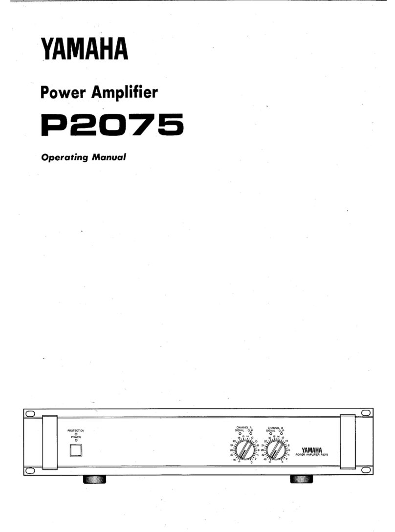
Yamaha P-2200/2201 User manual

YAMAHA
AUTHORIZED
PRODUCTMANUAL
P-2200/2201
SYSTEMAMPLIFIER

P-2200/2201
OPERATING MANUAL

ABOUT THIS MANUAL
SCOPE
The P-2200isa system oriented amplifier, made to be
used inconjunction with mixers, consoles, frequency
dividingnetworks and speakers — those made by
Yamaha orbyother manufacturers. Like any power
amplifier, the P-2200's performance depends onsystem
design and installation, inaddition to itsown capabilities.
Thus, the P-2200 Operating Manual issystem oriented,
describing system design parameters and installation
techniques, as well as the operation and performance of
theP-2200.
Additionally, thismanual reviews a few of the basic
mathematic tools used insystem design,from dB to
Ohm'slaw.
ORGANIZATION
We recommend that you read the entire Operating
Manual. However, ifyou are using theP-2200 inan
existing system, and you are familiar with highpower
amplifiers, the BRIEFOPERATING INSTRUCTIONS,
Pages
One
1
&
2,
contain all the
information
necessary
for
basic connections and operation.
The SPECIFICATION sections, (Sections THREE
andFOUR) are highlydetailed, includingoscilloscope
photos,and discussions of the P-2200's excellent
performance specifications. The lastpart of the
SPECIFICATIONS section isa discussion of the
advantages ofprofessional equipment, like the P-2200,
compared to hi-fi orsemi-pro equipment.
The INSTALLATION AND DETAILED
OPERATION section, which begins onPageSIX 1,
includes more complete instructions, special considera-
tions for using the P-2200"onthe road,"as well as in
permanent commercial and studio installations. This
section also covers grounding and shielding concepts,
cabling considerations, and several other topics.
TheAPPLICATIONS section, which begins on Page
SEVEN 1,discusses the use of the P-2200 inseveral
typical setups, andincludes wiring diagrams. This section
also covers other devices that are normally associated
with a power amplifier, from graphic equalizers to
compressor/limiters.
The APPENDIX, onPage EIGHT 1,discusses
definitions of a numberof the terms usedinthe manual,
and reviews some of the basic mathematic tools used in
system design,suchas the dB,Ohm's law, voltage
division, and power formulas.
NOTE: The P2201 is identical to the P-2200 except
there are no Peak Reading Meters.

THE P-2200/2201 BRIEFOPERATINGINSTRUCTIONS SECTION ONE
INTRODUCTION SECTIONTWO
GENERAL SPECIFICATIONS SECTION THREE
PERFORMANCE GRAPHS & A DISCUSSION OF SPECIFICATIONS SECTION FOUR
THE DISTINCTION BETWEEN PROFESSIONAL AND HI-FI EQUIPMENT SECTION FIVE
IMPEDANCE
1
OPERATINGLEVELS
2
DYNAMIC RANGE
2
GAINOVERLAPANDHEADROOM
4
INPUT SENSITIVITYRATINGS
4
PROFESSIONALEQUIPMENTADVANTAGES
4
INSTALLATION AND DETAILED OPERATION SECTION SIX
PHYSICALMOUNTING
1
CABLING AND IMPEDANCE MATCHING
2
ACTIONS OF THE P-2200 PROTECTION CIRCUITS
13
GROUNDING AND SHIELDING
13
AC: POWER, FUSES,ACCESSORYOUTLETS,WIRING,SAFETY
16
MONO OPERATION
17
APPLICATIONS
BIAMPLIFICATIONAND TRIAMPLIFICATIONSECTION SEVEN
1
ECHO, REVERBAND DELAY 3
COMPRESSION AND LIMITING
3
EQUALIZATION, HIGH AND LOW PASS FILTERS4
SPEAKER PROTECTION
SPECIFICAPPLICATIONS
6
7
APPENDIX
SECTION EIGHT
DEFINITION OF TERMS: dB, dBV, dBm and dBSPL
1
SPECIAL USEOF dB (VOLTS) INTHIS MANUAL
1
OHM'S LAW 2
POWER
2
IMPEDANCE
3
SERIESANDPARALLELIMPEDANCECONNECTIONS
3
VOLTAGE AND CURRENTDIVISION 4
BALANCED, UNBALANCED, AND FLOATING CIRCUITS
5
TRANSFORMERS
5

THE P-2200/2201 BRIEF OPERATING INSTRUCTIONS
Fig.1A- P-2200 Front Panel
Fig.1B- P2201Front Panel
A. InputAttenuators
Calibrated, stepped inputattenuators lower input
signal levels ahead of amplification stages.
B.PeakReading Meters (P-2200only)
Meters display instantaneous (peak) power output
into
an
8-ohmload
over
a
full
50dB range;
"0dB"
=
100Watts into8 ohms.
C.ThermalWarning Indicator
Warns of overheating before thermal protection
circuit turns off the AC power.
D.PowerIndicator
Glows when the power switch is"on."
E.On-Off Switch
Controls AC power to the P-2200or P2201.
NOTE: The P2201 is identical to the P-2200 except
thereare no Peak Reading Meters. Both are made to be
mounted in a standard 19" wide electronic equipment
rack. Each of them takes up 7" (17.6cm) of vertical
space, and extends 13" (33.0cm) behind its front panel.
For portable racks, we recommend bracing the rear of
the amplifiers.

Fig.2A- P-2200Rear Panel*
Fig.2B- P2201 Rear Panel*
A. Input Connectors
The two XLRinput connectors on each channel are
unbalanced and arewired inparallel with each other
and with the two phone jacks(tip/sleevetype).
B.Input Polarity Switch
Determines the polarity of the twoXLRinput
connectors (Pin
2
orPin
3
"
hot
");
does
not
affect
the
two phone jacks. See diagram onthe rear panel.
NOTES:
1. Input impedance is 25k-ohms minimum; +4dB
(1.23V) produces 230 watts output into 8 ohms
(44.7V).
2. Input channels may be parallelled by connecting
them together with phone to phone or XLR to XLR
cables as shown on Page SIX 7.
3. Input transformers for matching or isolation,
should be located several inches from the P-2200 or
P2201's
power transformer
for
maximum
hum
rejection.
C.Output Connectors
Standard 5-way binding posts (3/4" spacing) accept
banana plugsordirect-wired connections.
NOTES:
1. Maximum power output into 8 ohms is 230 watts;
power output rises at lower impedances.
2. Protection circuitry towers power output when
load impedance falls below 2.5 ohms.
D.AC Power Cord
Forthe U.S.and Canadian models, the P-2200/2201
require 117 VAC 50or 60Hz line (105V min., 135V
max.; 8 amps max. at 120volts).
For the Australian model: 240V AC 50 or 60Hz.
For other territories' models, an internalvoltage
selector (220 V/240 V switchable) isprovided near the
rear panel. Inthis case 220 V isfactory-preset. Ifyou
want
to
change
into
240
V
line,
consult
your
nearest
Yamaha dealer.
E.Fuses
7amp,125volt(x2),typeAGC (3AG);U.S.and
Canadian models only. 4 amp, 250 volt (x2);other
territories models. Fuses shouldalways bereplaced
with
same
size
and
type.
If
the
fuses
blow
consistently,
the amplifier should bechecked by a qualified Yamaha
service technician.
F.AC Accessory Outlets
These convenience outlets aremade forlow power
cooling fans. Notprovided incertain areas.
The rear panels shown here are subject to U.S. specifications.

INTRODUCTION
The P-2200 is notjust"anotherbigamplifier;"itis
an exciting new approach to high power sound. Yamaha's
leadership is clearly demonstrated by the P-2200's pro-
fessional features, sophisticated design, and uncom-
promising performance.
PEAK READING METERS*
Instead of the more common and slow responding
VU meters, the P-2200has PEAK READING METERS
that
accurately display
a
full
five
decades
(50dB)
of
output level. The peak meters have large, illuminated
faces marked with dB and with watts into 8 ohms. The
fast responding meters provide a better way to see the
program dynamics, the transient power demands placed
on the system, and the available headroom. By indicating
headroom, the meters help the operator avoid over-
driving the system, thereby preventing the "clipped"
waveforms so dangerous to drivers and loudspeakers.
CALIBRATED INPUTATTENUATORS
The P-2200 has log-linear INPUT ATTENUATORS to
complement itspeak reading meters. The input attenua-
tors are marked in22dB-calibrated steps, detented for
extra accuracy. The attenuators provide a smooth, noise
free transition from the highest to the lowest audio level.
dB-calibrated
input
attenuators
have
numerous
advantages: onthe road, they allow predictable and
repeatable setups; incommercial sound applications,
they allow easy, accurate inputsensitivity adjustments;
instudios or discos, they letoperators simultaneously
adjust the level oftwo channels (or two programs on
separate amplifiers) with precise tracking.
INPUT AND OUTPUT CONNECTIONS
INPUT CONNECTORS for each channel include one
"male" and one "female" XLRconnector (unbalanced)
plustwo parallel phone jacks. This provides the flexi-
bility
necessary
for
convenient bridging
to
another
amplifier, as well as for adapter-free connection to
almost any mixer. A POLARITY switch allows either
pin2 or pin3 of the XLRto bechosen as the "hot"
lead, satisfying DIN/JIS or USA standards. Outputs are
standard fiveway binding posts, usable with highcurrent
"banana" plugsordirect wired connections.
MONAURAL OPERATION
The P-2200 may beconverted to a monaural "super
amplifier" byinserting two matched transformers
ahead of the inputs, feeding the same signal to both,
and reversing the POLARITY switch on one input.This
creates a transformerless balanced output, the speaker
load "bridged" across the "hot"terminals of both
channels. Inthis mode, the P-2200 issuitable for
driving almost any load, including highly reactive70-volt
commercial speaker lines. With a full 400 watts into
16ohms, the P-2200 inmono mode eliminates theneed
for several smaller 70-volt amplifiers.
PERFORMANCE
The P-2200'sperformanceisasimpressiveas its
features. At a sustained output of 230 watts into 8 ohms
(for each channel), there isplenty of punch to reproduce
the powerful peaks essential to clean studio monitoring.
Highpower handling also makes the P-2200 an unbeat-
able choice for live rock ordisco sound systems, where
an amplifier can really "cook" all nightlong.Power alone
is
no
virtue;
the P-2200
has
ultra-low
distortion,
less
than
0.05%THD at full rated power - the kind of low
distortion that isundetectable by even the most critical
listeners.
Ahighdamping factor of better than 300 at
frequencies below 1kHzreduces the tendency for
speaker cone overshoot, giving tighter and better defined
bass response. Onthe other end, the P-2200's frequency
response extends well beyond 100kHz, enabling itto
accurately reproduce the most complex musical wave-
forms — even the tortuous output of today's synthe-
sizers. However, highfrequency response has notbeen
achieved at the expense of stability; infact, the P-2200
isrock steady. Even when connected to highly reactive
multi-speaker loads, there isnotendency to shut down
or"take off" into spurious oscillation.
MECHANICAL CONSIDERATIONS
The P-2200 isconstructed to withstand the high "G"
forces encountered on the road. Itssolid front panel
mounts inany standard 19-inchrack, and, for a large
amplifier, the P-2200 weighs a modest 44 pounds
(20kg)** Front panel controls and meters are recessed to
avoiddamageor accidental settingchanges,and are
further protected bya pair of sturdy carryinghandles.
Inside
and
out,
the P-2200
is
extremely reliable.
Still,
should
service
ever
be
required, the
unit
is
designed
for
easy access. Massive side-mounted heat sinks are
designed forefficient cooling, making fans unnecessary
inallbutthe most severe thermal operating conditions.
Four non-conductive feet ensure proper air flow when
the amplifier isshelf mounted, and avoid inadvertent
ground loops. Multiple protection circuits make the
amplifier nearly abuse proof and eliminate the need for
troublesome DCpower supply fuses.
*The P2201 does nothave the Peak Reading Meters.
** The P2201 weighs 42 pounds (19kg)
GENERAL SPECIFICATIONS
Power Output PerChannel: (Refer to Figure 3. Ambient
room temperature for tests: 25-degrees Centigrade.)
200 Watts continuous average sine wavepower into
8
ohms
with
less
than
0.05%
THD,
(Total
Harmonic
Distortion), over a bandwidth of 20Hz to 20kHz,
both channels driven.
230Watts continuous average sine wave power into
8
ohms
with
less
than
0.05%
THD,
at
1
kHz,
both
channels driven.
Frequency Response: (Referto Figure 5.)
+0dB,-0.5dB, 20Hz to 50kHz.
TotalHarmonic Distortion: (Refer to Figure 6.)
Less than 0.005% @ 50 Watts, 8 ohms, 1kHz.
Less than 0.01%@ 150Watts, 8 ohms, 20Hz to
20kHz.
Intermodulation Distortion: (Refer to Figure 7.)
Less than 0.01% using frequencies of 70Hz and
7kHz, mixed ina ratio of 4:1,single channel power
output of 150Watts into 8 ohms.
InputSensitivity:
An input of +4dB* (1.23V),±0.5dB,produces an
output of230Wattsinto8 ohms (maximum output
power),INPUT attenuator set formaximum level.
Input Impedance:
25k-ohms, minimum(unbalanced).
Damping Factor: (@ 8 ohms / (Refer to Figure 8.)
Greater than 300 at any frequency from 20Hz to
1kHz;greater than 70 at any frequency from 20Hz
to 20kHz.
Actual Output Impedance: (Refer to Figure 9.)
Less than 0.04ohms, from 20Hz to 10kHz.
HumandNoise:
At least 110dB signal-to-noise ratio (l.H.F./A.S.A.
No.Z24.3-1944).
Rise Time:
3.8microseconds, or better (10%-90% of 1 volt @
1kHzsquare wave output).
Slew Rate:
45 volts per microsecond, or better (at 175Watts into
8ohms, 200kHz square-wave input).
ChannelSeparation: (Refer to Figure 10.)
Atleast 82dB at 1kHz,at least 75dB at 20kHz.
*Inthese specifications, when dB represents a specific voltage,
0dB is referenced to 0.775V. "dB" is a voltage level, whereas
"dBm" is a power level. 0dBm is referenced to 1mW (0.775V
driving a 600-ohm termination). For example, when 12.3V is
fed to a high impedance, the level is designated "+24dB." When
+24dB (12.3 volts) drives a 600-ohm termination, the level is
designated "+24dBm." The level in "dB" is specified, wherever
applicable, to avoid confusion when the input is fed by various
low and high impedance sources. See the APPENDIX beginning
on Page EIGHT 1 for a further discussion of dB.
PhaseShift: (Referto Figure 11.)
20Hz to 20kHz, ±10degrees.
OffsetVoltage:
Less than ±10mVDC.
UnitStep Function Response: (Refer to Figure 27.)
Seescope photo (Page FOUR 4) and discussion,
PageFOUR 6.
Thermal Specifications:
Massive black anodized heat sinksare thermally
joined with the chassis, thereby utilizing the entire
amplifier as a heat sink.
Protection Circuits:
Thermal warning lightturns on when heat sink
temperaturereaches100-degreesCentigrade.
Aself-resetting thermal switch shuts down the AC
power ifthe power transformer winding temperature
reaches 130-degrees Centigrade. See Page SIX13for
power overload circuit specs.
TurnOn/Turn Off Specs:
There isnoturn offtransient; the turn on transient
is
minimal
(see
Page
SIX
13).
Warm
up
time
is
less
than 0.2seconds.
Power Requirements:
For the U.S.and Canadian models: AC, 120Volts
nominal, 50-60Hz (105Vmin.,135Vmax.); 8
amperes maximum at 120VAC; 960 volt-amperes
maximum at120Volts; approximately 57volt-
amperes atidle.
For other territories models: 1,300 Watts, 220 or240
Volts AC nominal, 50-60Hz.
Efficiency: (Refer to Figure 12.)
As highas 63%;see PageFOUR 2.
NOTE: All performance specifications are made on U.S.
and Canadian models at an AC line voltage of 120 Volts
±1%, using a ±1% nonreactive load resistor at an
ambient room temperature of 25-degrees Centigrade.
Also effective for other territories' models.
InputConnectors:
One"male"andone "female"XLRconnector in
parallel,
pin
2
"hot,"
pin
3
connected
to
pin
1
(shield); switchable
for
pin
3
"hot."
XLR'sare un-
balanced and inparallel with two tip-sleeve
(standard) phone jacks.
Output Connectors:
Standard 3/4-inch spacing, "5-way" binding posts.
Meters and Indicators:
Two peak reading meters (one per channel)indicate
the instantaneous power output, over a 5-decade
(50dB) range. "0dB" represents 100Wattsinto
8ohms. (P-2200only)
One "power ON" indicator LED; one "Thermal
Overload" indicator LED.
MeterRise Time (P-2200 only):
Less
than
10
milliseconds;
(-40dB
to
0dB
onthe scale).
MeterRelease Time (P-2200only):
Less
than
0.8
seconds; (0dB
to
-20dB
on
the
meter scale).
MeterAccuracy (P-2200 only):
See graph, Figure 13,PageFOUR 2.

Controls:
22-position, log-linear, detented, and dB-calibrated
INPUTATTENUATORS (one per channel)
attenuate inputsignal in2dB steps from 0dB
attenuation to -34dB, then steps of -37dB,-42dB,
-50dB, infinity; Power (ON-OFF)switch; INPUT
POLARITYswitches.
Fuses:
AGC (3AG) type, 7-amps x 2 parallel fuses forthe
AC lineinput(U.S.andCanadian models).
4-amps x 2 parallel fuses for the AC line input
(other territories' models).
Dimensions:
Mounts ina standard 19-inch(48cm) rack. 7" high
(17.6cm);maximum depth behind front panel is
13"(33.0cm); maximum depth including front
handles 14-1/2"(37.9cm).
Weight:
P-2200; 44 pounds(20kg), P2201;42 pounds (19kg).
Color:
Semi-gloss black.
MONAURAL MODE SPECIFICATIONS
Power Output:(Refer to Figures 14 and 15.)
400
Watts
continuous
average
sine
wave
power
into
16
ohms
with
less
than
0.05%
THD,
20Hz
to
20kHz.
Frequency Response: (Referto Figure 16)
+0dB,-1dB,20Hz to 50kHz.
Total HarmonicDistortion:(Refer to Figures 17 and 18.)
Less
than
0.01%
@
300
Watts
into
16
ohms at 1kHz.
Intermodulation Distortion:
Lessthan 0.05% using frequencies of 70Hz and 7kHz,
mixed ina ratio of 4:1,at a power output of 200
Watts into 16ohms.
InputSensitivity:
An inputof 0dB (0.775 Volts),±0.5dB,produces an
output of 200Watts into16ohms (INPUT attenuator
set for minimum attenuation, maximum level).
InputImpedance:
25K-ohms minimum (unbalanced).
DampingFactor: (@ 16 ohms) (Refer to Figures 19
and20).
Greater than 220at any frequency from 20Hz to
1kHz;greater than 100at any frequency from 20Hz
to 20kHz.
Humand Noise:
At least 110dB signal-to-noise ratio (I.H.F./A.S.A.
No.Z24.3-1944).
Slew Rate:
35volts permicrosecond, or better, at100Watts into
16ohms,200kHz square wave input.
Specifications subject to change without notice.

PERFORMANCE GRAPHS &
ADISCUSSION OF SPECIFICATIONS
NOTE: In the discussion beginning on Page FOUR 5,
references to specific specifications assume normal stereo
operation (notmono operation) unless otherwise indicated.
Normal(Stereo) Graphs
Fig.3 - Power Bandwidth vs Load Impedance Fig.4 - Load Impedance vs Output Power
Fig.5 - Frequency Response vs Load
Fig.6A - T.H.D.vs Output Power at8 Load Impedance
(bothchannelsdriven)
Fig.
6B
-
T.H.D.
vs
Output
Power at
16
Load Impedance
(both channels driven)
Fig.7 - Intermodulation Distortion vs Power Output at
8and 16 Load Impedance Fig.8 - Damping Factor vs Frequency at 8 Load
Impedance

Fig.9 - Actual Output Impedance vs Frequency Fig.10- Crosstalk (Channel Separation)
Fig.11- Phase Response vs Frequency Fig.12- Power Consumption
Fig.13- Peak Program MeterAccuracy (P-2200 only)

MonoModeGraphs
Fig. 14- Power Bandwidth vs Frequency (Mono Mode)
at 16 Load Impedance Fig.15- Load Impedance vs Output Power (Mono Mode)
at 0.1%
T.H.D.,
1kHz
Fig.16- Frequency Response (Mono Mode) at 16 Load
Impedance
Fig.17- T.H.D.vs Power Output (Mono Mode) at 16
Load Impedance
Fig.18- T.H.D.vs Frequency (Mono Mode) at 16 Load
Impedance
Fig.19- Damping Factor vs Frequency (Mono Mode) at
16 Load Impedance
Fig.20- Actual Output Impedance (Mono Mode) vs
Frequency

The following are actual oscilloscope photographs
madebyan independent testing laboratory. The close
vertical
alignment
of
input
and
output
traces
in
Fig.
21
through
23
depicts
very
low
phase
shift,
so
the
amplifier
will
not
alter
musical
wave
shapes.
Fig.21 - 10Hz Square-Wave Response
The output waveform displays very respectable
low frequency
response.
The slight
"
tilt
"
shows
a
DC
gain
of
unity,
which
prevents
damage
to
speakers inthe event any DCoffset isfedto the
amplifier input.
Fig.22 - 1,000Hz Square-Wave Response
Near-perfect response isevident inthe duplica-
tion
of the
input
waveform
by
the
output
wave-
form. There are no "squiggles" orspikes, mean-
ing there Isnoringing orovershoot.
Fig.23- 20,000Hz Square-Wave Response
The extremely fastand symmetrical rise and
falltimes of the amplifier are evident, demon-
stratingthe ability to accurately reproduce
musical waveforms and harmonics well beyond
the range ofhuman hearing.
Fig.24- 1,000Hz Sine Wave, shown with Highly-
Magnified Noise and DistortionComponents
Even
at
full
230 watt
output
(8-ohms), the
P-2200's distortion isso low that itisalmost
burried inthe noise, which isat least 110dB
below the
sine
wave
output.
The
sine
wave
is
cleanandsymmetrical.
Fig.
25-20,000Hz
Sine
Wave,
shown
with
Highly-
MagnifiedNoise and Distortion Components
While no amplifier should ever have topro-
duce 230 watts continuous output at 20kHz,
the
P-2200
does
it
with
low
distortion,
and
symmetrical reproduction. As InFig.11,the
noise (magnified here) isactually better than
110dBbelow the sine wave.
Fig.26- Square-Wave Response intoa Highly-
Inductive Load (at 1kHz)
The ability of the P-2200 tomaintain a
sharply defined square wave output into a
reactive load demonstrates stability under the
worst conditions. There isstill a complete lack
of unwanted ringing,as well as low phase shift.
Fig.27 - Unit-step Function Response

POWER OUTPUT
Types ofPower Ratings
Peak power refers to the maximum undistorted power
output of an amplifier. Most amplifiers cannot sustain
their peak power ratings for long periods of time without
externalcooling fans. Because there are many different
methods of rating anamplifier's peak power, itishard to
objectivelycompare the peak power ratings of two
amplifiers. The peak power rating isprimarily useful
fordetermining an amplifier's ability to reproduce the
peaks and transients ina musical program, peaks which
may be20dB or more above the average power level.
The ability to accurately reproduce these high power
peaks ina musical program isone of the most important
advantages of the P-2200 as compared to a smaller
power amplifier.
"RMS"power isactually a misnomer for average
power. Average power isusually measured with a sine
wave input signal, and isequal to the amplifier'sRMS
output voltage squared and then divided by the load
impedance (see Appendix). Because RMSvoltage isused
inthe formula, the resulting power rating iscommonly
called "RMS power." While itmeans the same as "RMS
power," to bemore accurate, the P-2200 israted inwatts
of "continuous average sine wave power."
Since the P-2200 isa professional power amplifier,
not sold forhome hi-fi use, itisnot required to meet the
power rating standard set by the FTC (Federal Trade
Commission), a standard meant forconsumer power
amplifiers. However, the P-2200 ismeasured under
severe conditions which simulate the most demanding
professional usage. Thus, the P-2200 would easily meet
the FTC ratings for consumer amplifiers. Inaddition,
the P-2200 user has the benefits of professional features
andreliability.
Reasons for a HighPower Amplifier
An interesting characteristic of the human ear is
described bythe "Weber-Fechner" law. Inits general
form, the law applies to allour senses:
Theamount of additional stimulus needed to
produce a perceptible change isdependent onthe
amount of stimulus already present.
Inmathematical terms, the Weber-Fechner law
suggests that the human ear responds to changes in
sound level ina logarithmic manner. More simply this
means that for a sound to seem twice as loud, itrequires
approximately ten times as much acoustic power (and
thereforeten times as much amplifier power). Thus, the
P-2200's highpower output capabilities areextremely
valuable.
One of the other benefits of highpower output isthe
ability of the amplifier to easily reproduce highpeak
power transients (which may be100times the average
program power, or even more). This subject isdiscussed
further
on
Pages
FIVE2 and
FIVE
4.
Power Output versus Load
Within its maximum limits, the P-2200 acts likea
perfectvoltage source (see Appendix), that is,itspower
output
rises
with
decreasing
load impedance.
When
the
load impedance drops below 2.5 ohms, the P-2200's
protection circuits begin to limit the power, resulting
inthe curve shown inFigure 4 (normal operation) and
Figure 15(mono operation).
DISTORTION (Referto Figures 6A-B, 7,17,18)
The P-2200 isdesigned to have the lowest possible
distortion. There are many differentforms of distortion,
however, and comprehensive distortion ratings offera
means to compare the performance of different
amplifiers.
HarmonicDistortion, is characterized by the appear-
ance at the amplifier output of harmonics of the input
waveform which were not present inthe original input
waveform. Total Harmonic Distortion, orT.H.D.isthe
sum total of all of these unwanted harmonics expressed
as a percentage of the total signal.
Harmonic distortion, inan amplifier, can becreated
inany of several ways. The T.H.D.rating of a power
amplifier refers to creation of unwanted harmonics by
the amplifier during "linear" operation (normal input
and output levels, impedances, etc.). Harmonic distortion
is
also
created by
"clipping,"
a
form
of
"non-linear"
operation, which occurs when the signal level atan
amplifier's inputishighenough to drive the amplifier
beyond itsrated maximum output. The amplifier, in
attempting to reproduce this signal, reaches its maximum
outputvoltage swing before itreproduces the top of the
signal waveforms. Since the outputvoltage cannot rise
any farther, the tops of the waveform are "squared off,"
or clipped, as that shown inFigure 65.Clippingdis-
tortion adds odd upper harmonics (3rd harmonic,
5th,etc.) to the original signal. (Input clipping would
besimilar, where the inputstage of theamplifier is
overdriven bya highlevel inputsignal.) The P-2200 has
wide inputheadroom and extremely high peak power
output capabilities (headroom) to help avoid the pro-
blems of clipping distortion.
Another form of harmonic distortion that occurs in
some power amplifiers iscalled crossover distortion. *
Crossover distortion can becaused byimproper bias inthe
outputtransistors of an amplifier. The amount of cross-
over distortion stays the same whether the signal islarge
or small, so the percentage of distortion goes down as
the
signal
level
goes
up.
Thus,
an
amplifier
with
crossover
distortion may sound relatively distortion freeat high
output
levels,
yet sound
"
fuzzy
"
atlow
levels.
Some
amplifiers have internal adjustments which enable a
service technician to control the amount of output
transistor bias, and therefore control the distortion. The
P-2200 has automatic biasing circuitry which needs no
adjustment and avoids crossover distortion under all
operating conditions.
Fig.28A - Large Amplitude SineWave with Crossover
(notch) Distortion.
Fig.28B - Smaller Amplitude SineWave with same amount
(higher %) ofCrossover (notch) Distortion.
"Crossover,"in this case. refers to the transition between the
positive half and the negative half of the output voltage wave-
form in a "push-pull" class B or AB power amplifier: it has
nothing to do with the crossover used to divide frequencies in
aspeakersystem. See Figure28.

Intermodulation Distortion,or I.M.ischaracterized
bythe appearance intheoutput waveform of fre-
quencies that are equal to sums and differences of
integral multiples of two ormore of the frequencies
present intheinputsignal. The difference between inter-
modulation distortion andharmonic distortion isthat
two ormore different frequencies must bepresent to
produce intermodulation distortion (only one frequency
isneeded for harmonic distortion to appear), and that
intermodulation distortionproducts may notbe
harmonically related to the original frequencies. Like its
harmonic distortion figure, theintermodulation dis-
tortion inthe P-2200islow enough to bevirtually
inaudibleeven inthe most critical situations.
DynamicFrequency Response Shiftisrelated to both
harmonic and intermodulation distortion. When high-level
lowand highfrequencysignals are presentinthe same
waveform,
the
high
frequency
signals
"ride"
on
top
of
the
lowfrequency waveforms (see Figure 65,PageSEVEN 1).
If
amplifier
headroom
is
inadequate,
the
lowfrequencies
may
"push"
the
high
frequencies above the
output
limits
ofthe amplifier,clippingthemoffthe waveform (Figure
65C). Thelow frequencies may remain unaltered, butthe
highfrequencies are severely reduced. At thesame time,
harmonics of the highfrequencies are produced which
addto the super highfrequency content of thesignal.
Thus,along with the distortion created bythe clipping,
the frequency response of theoriginalsignal isdrastically
altered. Thistype of distortion can bereduced byin-
creasingsystem headroom (using a more powerful
amplifier like the P-2200), and bybiamplifying the
systemasdiscussedonPageSEVEN 1.
Theextremely low distortion figures of the P-2200
indicate itsoverall qualityand mean that itssound will
beprecise and natural.
FREQUENCY RESPONSE (Refer to Figures 5 & 16)
Thefrequency response of theP-2200 describes the
variation initsoutputsignal level with frequency when
the
input
signal
is
held constant. Theextremely
"
flat
"
frequency response curve of the P-2200isanindication
ofitsoverall quality and itsability to respond to upper
and lower harmonics of signals all the way to the
extremes oftheaudio spectrum.
Because extreme stability isnecessary for some types
of commercial sound applications, notably 70-volt lines
(seePageSEVEN 11),some manufacturers restrictfre-
quencyresponseorallow relativelyhighdistortion in
returnfor increased amplifier stability.TheP-2200,on
theotherhand,has excellent frequency response and
ultra-low distortion, yet isinherently stable underthe
most difficult loads, even inthe "mono"mode.
Thefrequency response of the P-2200 has been
intentionally limited,however, atvery low frequencies
(sub-audio). Because ofthis,severe low frequency
transients, orDCoffset, appearing at the inputto the
P-2200are unlikely to damage a speaker load. Other
amplifiers which are DCcoupled throughout may have a
"flatter"
sub-audio frequency
response,
but
this
makes
them capable of amplifying dangerous DCinputvoltage
orsub-audio transients and delivering them (at high
power) to a speaker.
OFFSET VOLTAGE
This specification indicates the amount of DCvoltage
naturally present at the output of the amplifier. A high
DC voltage could damage the loudspeaker load; the
±10mV(10one-thousandths of a volt) level from the
P-2200isinsignificant.
UNIT STEP FUNCTION RESPONSE (Referto Figure 27)
Aunit step function islike the leading edge of a
square wave; itgoes up,butnever comes down. The
response to this inputindicates the output of the P-2200
for a DCinputsignal which mightcome from a faulty
direct coupled preamplifier or mixer. Notethat the
P-2200 will notreproduce a DCvoltage fed to itsinput,
thus adding an extra measure of loudspeaker protection.
POWER BANDWIDTH (Refer to Figures 3 & 14)
The power bandwidth of the P-2200 isa measure of
itsability to produce highpower outputover a wide
frequency range. The limits of the power bandwidth are
those points where the P-2200 can only produce 1/2the
power that itcan produce at 1000Hz. While the
frequency response ismeasured at relatively low power
output(1watt), the power bandwidth ismeasured atthe
P-2200'sfull power output(before clipping). The power
bandwidth
of
the
P-2200
is
quite
"
flat
,"
and extends
to
200kHz, well beyond the limitsof the audio spectrum.
Thewide power bandwidth of the P-2200 means that
itcan reproduce highlevel upperharmonics of a signal
as easily as itcan reproduce mid-range fundamentals. It
means
that
you
get
full
power performance
from
the
P-2200over theentire audio frequency spectrum. Thisis
especially important when the amplifier iscalled upon
to reproduce musicalmaterial with highenergy over a
wide frequency range, such as rock and roll.
PHASE RESPONSE (Referto Figure
11
)
Thephase response of the P-2200isa measure of the
amount of time delay itadds to different frequencies.
An amplifier with perfect phase response would introduce
equal time delay atall frequencies reproduced. The
P-2200's worst case phaseshift of -10degrees at 20kHz
corresponds to a 1.4microsecond (1.4millionthsofa
second) delay period which isinsignificantineven the
most critical audioapplications.
Fig.29 - Waveform ofAmplifier with PoorPhase Response.
An amplifier with poor phase response would change
the shape of a waveform that was made upof a funda-
mental frequency and several harmonics bydelaying
each harmonic differently. The effect might besimilar
to that shown inFigure29.
CHANNEL SEPARATION (Referto Figure 10)
Thisspecification indicates the output from one
channelwhen a signal is fed to the other channel. The
P-2200'schannel separation isvery good, which means
that
even
critical
stereo programs
will
beunaffected by
crosstalk between channels.

HUMAND NOISE
Humornoise froma power amplifier disrupts a
program, and is irritating to a listener. Humand noise
could beconsidered a form of distortion. The P-2200's
humand noise are so low that they arecompletely
inaudible under any normal listening circumstances.
RISE TIME
Rise time isa measurement of the amount of time an
amplifier requires to respond to a square wave at a
specifiedfrequency. The rise time of an amplifier isan
indication of its frequency response. A fastrise time
corresponds to a wide frequency response. The P-2200's
rise
time
specification
is
measured
with
a
1000Hz
square
waveoutput signal of one volt peak-to-peak amplitude.
The rise time is the time the amplifier requires to change
from 10%(0.1 volt)to 90% (0.9volt)of itsoutput. To
improve measurement accuracy, the firstand last 10%
are normally not included inthe test (any slight non-
linearities that occur inthe test signal or the amplifier
could lead to measurement error).
SLEW RATE
Slew rate isa measure of a power amplifier's ability
to follow a fastrising waveform athigherfrequencies
and higher power outputs than therise time measure-
ment.The P-2200's slew rate ismeasured with a 200kHz
square wave inputsignal, at175Watts outputpower
into 8 ohms.
Itmightseem reasonable to assume that the fastest
slew rate for an audio waveform occurs at20kHz.
However, this isnotthe case. When one frequency is
superimposed upon another, the combined waveform
has a slew rate that is greater than theslew rate of
either signal byitself. The actual value oftheslew rate
ofone ofthese waveforms (or any waveform) depends
not only onthefrequency, buton theamplitude of the
waveform as well. Thus, thecriteria fora good slew rate
specification, which indicates that anamplifier can
reproduce these combination waveforms, varies with
the maximum power output capability of theamplifier.
Thehigher the power, the higher the required slew rate.
With a 45 volts/microsecond slew rate, the P-2200 can
easily reproduce even the most extreme audio wave-
forms at its full power output.
INPUTIMPEDANCE
Theinput impedance of the P-2200 ishighenough
to allow itto beused with most semi-pro devices, or to
be
used
as
a
"bridging"
load
for
a
600-ohm source.
PageSIX2 details inputimpedance andlevel matching
forthe P-2200.
INPUTSENSITIVITY
The P-2200's input sensitivity indicates the input
drive voltage needed forthe P-2200 to produce its
rated output of 230 watts into8 ohms (input attenua-
torsare adjusted to maximum clockwise rotation for
minimum attenuation).
PROTECTION CIRCUITS AND
THERMAL SPECIFICATIONS
See the discussions under INSTALLATION, on
Page SIX 13.
GAIN
Gainis the ratio of the P-2200's output voltage toits
input voltage.Maximum gain occurs when the input
attenuatorsareset forminimum attenuation. Ifthe input
andoutput voltageare specifiedindB, the voltage gain is
equal tothe differenceof the two dB numbers. As stated
underINPUT SENSITIVITY, an inputvoltage of +4dB
(1.23volts)produces an output power of 230 watts into
an 8-ohm load.230watts into 8 ohms implies an
output voltage of 43volts which corresponds to +35dB
(referenced to 0.775 volts, as used inthis manual). The
voltage gain of the P-2200,with its input attenuators set
for minimum attenuation, then, is31dB[(+35dB)-(+4dB)].
OUTPUT IMPEDANCE (Referto Figures 9 & 20)
The output impedance of the P-2200 isextremely
low. Thus, within itsoperating limits, the P-2200 is a
good approximation of a perfect voltage sourceand will
deliver increasing power levels into lower impedance
loads ina linear fashion according to Ohm's law. The
Appendix discusses Ohm's law and the concept of a
perfect voltage source.
DAMPING FACTOR
Damping factor isa term that isderived by
dividing the load impedance (speaker orother load) by
the amplifier's outputimpedance. Thus, a high damping
factor indicates a low outputimpedance at a specified
load.
The cone/voice-coil assembly of a loudspeaker gains
inertia during its back and forth movements. This
inertiacan cause itto "overshoot," that is, to continue
movement inone direction, even when the amplifier
is trying to pullitback inthe other direction. An
amplifierwith a low output impedance can "damp"
(reduce) unwanted loudspeaker motions, as explained
below.
Fig.30A - Speaker Cone at Rest
Fig.30B- Speaker Cone moved outward by Postive-Going
Voltage from Amplifier.
Fig.30C -
Voltage from Amplifier has dropped to Zero but
Speaker Conehas moved back PAST itsrest position (overshoot)
andisproducing a voltage ofitsown: "Back EMF"

During the "overshoot" movement, the voice coil of
theloudspeaker interacts with the loudspeaker's magnetic
assembly to produce a voltage called "back E.M.F."
(electro-motive force).Thisaction issimilar to the
operation of a dynamic microphone. Ifthe amplifier's
output impedance islow, this "back E.M.F."voltage is
shunted through the amplifier's output circuits to
ground,and back to the voice coil. Since the path from
the voice coil, through the amplifier's output circuits,
and back to the voice coil isa complete circuit, a
current flowsinthe voicecoil. This current, causes
the voice coil to act like an electro-magnet; the electro-
magnet (voice coil) interacts with the magnetic assembly
of the loudspeaker, and the unwanted overshoot is
reduced (amagnetic braking action).
Fig.31 - Current produced by"BackEMF"follows path
through Amplifier's Output Impedance to speaker-coil.
Ifthe amplifier's output impedance islow (con-
siderably less than the impedance of the loudspeaker
voice coil), this damping action islimited only bythe
resistance ofthe voice coil combined with the resistance
of the speaker lead wires. While the value of a high
damping factor inreducing cone overshoot isdisputed,
the P-2200's highdamping factor isevidence of good
overallengineeringdesign.

THE DISTINCTION BETWEEN
PROFESSIONAL AND HI-FI
EQUIPMENT
Inmost applications, a variety of auxiliary equipment
will beconnected to the P-2200, including: mixers, tape
machines, compressors, graphic equalizers, echo, time
delay, and reverb units,and just about any other audio
electronics imaginable. Regardless of the function of
auxiliary equipment, itwill undoubtedly fallinto one of
two general categories, professional type or hi-fi type.
Thefollowing criteria place most "semi-pro" equipment
inthehi-fi classification.
The distinction between professional and hi-fi equip-
ment isimportant primarily because itaffectsthe way it
will beused with theP-2200.Brand name, size, panel
colors,durability and subtleties infunction arenot the
significant differences. What matters isthat professional
equipment and hi-fi equipment usually operate at
differentinputand output levels, and require different
source and load impedances to function properly. The
P-2200 isdesigned to function well with other pro-
fessionalequipment, although ithas highenough input
impedance and sensitivity to yield excellent results with
hi-fi type equipment ifa fewprecautions are observed.
(These precautions are outlined inthe Installation sec-
tion of the manual.) The following paragraphs explain
how the specificrequirements differ for professional and
hi-fi (or semi-pro) equipment.
IMPEDANCE
The inputs of a piece of professional audio equipment
are usually designed to bedriven from a low impedance
source,
nominally
150
to
600 ohms, and its
outputs
will
drive low impedance (600 ohm or higher) loads. (Power
amplifier outputs are not considered inthis discussion.)
Professional inputand outputcircuits may be
unbalanced, butthey are often transformer isolated
(balanced orfloating), and use dual conductor shielded
cables, with 3-pin XLRtype connectors orTip/Ring/
Sleevephoneplugs.
The P-2200's inputsare unbalanced due to cost and
adaptability factors. To internally balance the inputs of
the P-2200 would require two matched inputtransfor-
mers with heavy shielding (to avoid hum pickup from
the P-2200's power transformer). Induced huminlow
level circuits, especially inlow level transformers, can
bea problem with any power amplifier, or other high
current device (such as a DC power supply). Highquality
external
transformers
with
less
shielding can achieve
the
same
results
with
a
substantial cost
savings.
In
addition,
the user can choose the optimum impedance ratio for
agiven situation, increasing the P-2200's adaptability.
Either the "matching transformer box" or "step up
transformerbox" described onPages SIX 3,and SIX 4
are suitable, so long as they are kept several inches
away from the P-2200.
Hi-fi (and semi-pro)equipment generally is designed
to bedriven froma 5,000-ohm (or lower impedance)
source, and its output willdrive10,000-ohm (or higher
impedance) loads. Hi-fi input and output circuits are
usually unbalanced, and use single conductor shielded
cables with 2-conductor connectors, either standard
phone plugs or phono plugs (alsocalled RCA orpin
plugs). Occasionally, the inputs of a piece of hi-fior
semi-pro equipment are professional XLRconnectors
which have been converted to a 2-wire, unbalanced
circuit byinternally connecting either pin 2 or pin3
to
pin
1.
The nature of unbalanced, balanced, and floating
circuitry isdiscussed further inthe Appendix of this
manual. For the purpose of this discussion, the most
significant point isthat an unbalanced circuit issome-
what more susceptible to hum and noise, especially if
there isany irregularity inthe grounding system.
NOTE: THEREISNOCORRELATION BETWEEN
"BALANCED" OR "FLOATING" AND CIRCUIT
IMPEDANCE.
Low impedance and highimpedance are relative
terms. A 150-to 250-ohm microphone isconsidered low
impedance, whereas a 10,000-ohm mic isconsidered
highimpedance. A 600-ohm lineisconsidered low
impedance, whereas 10,000-ohm, 50,000-ohm or
250,000-ohm lines are all considered highimpedance.
Sometimes, mics and lines with an impedance of 600
ohms to about 2000ohms are considered "medium"
impedance. NOTE: THE IMPEDANCE OF A CIRCUIT
SAYS NOTHING ABOUT ITS LEVEL.
While the exact transition between low and high
impedance is not clearly defined, the distinction isstill
important, primarily because the output impedance of a
source determines the length of cable that can be
connected between itand a load before a seriousloss
of highfrequencies occurs. The losses occur because all
cables,andespeciallyshieldedcables,havesome
capacitance between their conductors. Some guitar
coil cords may measure as highas 1000picofarads total
capacitance! A source impedance (such as a high
impedance mixer output) and the capacitance of a
cable form a type of low-pass filter a filter that attenu-
ates highfrequencies. This filtering effect,can be
reduced byusing low capacitance cable, byshortening
the length of the cable, byusing a low impedance source
or bysome combination of these methods.
Fig.32 - The Source's Output Impedance andthe Cable
Capacitance act as an "RC Lowpass" Filter which Attenuates
HighFrequencies.

Cables from highimpedance sources (5000 ohms and
up), should notbeany longer than 25', even iflow
capacitance cable is used; shorten the cables ifthe
impedance is higher. For low impedance sources of 600
ohms or less, cable lengths to 100'are relativelyeffective.
For very low impedance sources of 50-ohms or less,
cable lengths of upto 1000feet are possible with
minimal loss.However, the frequency response of the
source, the desired frequency response of the system,
and the amount of capacitance and resistance inthe
cable all play a role inany potential highfrequency
losses. Thus, these values are meant as guide lines, and
should not beconsidered fixedrules.
For short runs and insmaller systems with fewer
components, the performance of an unbalanced circuit
may be adequate. Ina long cable run,a balanced or
floating circuit tends to reject hum and noise pickup
better than an unbalanced circuit, and incomplex
systems, with severalcomponents separated bysome
distance and running on different AC outlets, balanced
orfloating circuitsmake proper grounding much easier.
Inany given situation, the decision to use a hi-fi
(semi-pro) device or a professional one should bebased
onthe specifications of the inputs and outputs of that
device and on the requirements of the application.
OPERATING LEVELS
Nominal professional line level isusually +4dBm or
+8dBm; that is,the average program level isapproxi-
mately 1.23Vrms (+4dBm), or 1.95Vrms (+8dBm)
terminated bya 600-ohm line.The peak level may
extend to about +24dBm (12.3Vrms). The line (high
level) inputof professional audio equipment is
designed to accept levels on this order of magnitude
without overdrive (clipping distortion); most pro-
fessional equipmentcan bedriven to full output by
nominal +4dBm input(source) levels, although a few
unitsrequire +8dBm(1.95Vrms) at their input to
yield full output. Seethediscussion of"Gain Overlap"
on PageFIVE4.
Hi-fi type equipment operates atconsiderably lower
linelevelsthan professional equipment (with exceptions),
usually at -16dB(0.123volts) nominal levels. Notice we
use
the
expression
"
dB
,"
not
"
dBm
."
This
is
because
"dBm"denotes a power level (relative to 1mW,or
0.775V rms across a 600-ohm impedance), whereas "dB"
denotes a voltage level (as defined inthis manual) rela-
tive to 0.775V rms. This isa subtle distinction, and is
explained ingreater detail inthe Appendix on Page
EIGHT 1,and onPageTHREE1 of the specifications.
The nominal -16dB(0.123volts)levelof hi-fi
equipment isequal to 123mVrms (123one-thousandths
of a volt)across a 10,000-ohm or higher impedance line.
Peak program levels may reach or slightly exceed +4dB
(1.23Vrms across a high impedance line). Note that a
hi-fi unit capable of +4dB (1.23volts)maximum output
into
a
high impedance,
does
not
possess
adequate drive
for 600-ohm circuits with nominal +4dBm level require-
ments. Thus, hi-fi equipment is usually incapable of
driving professional equipment to its full rated output,
at least not without first reaching a high level of
distortion. Moreover, when the output of hi-fi equip-
ment (which isalmost always meant to beoperated
into a high impedance) is connected directlytothe low
impedance input of professionalequipment, the hi-fi
unit "sees" a partial short circuit. This may overload the
hi-fioutput, or itmay simply drop the output levelbya
few dB, depending onthe circuitry.The P-2200's input
sensitivity and inputimpedance are highenough to allow
its use with some hi-fi orsemi-pro equipment, however
it'sa good idea to check the specifications foreach
situation. The pointof this discussion, isthat impedance
andlevel are extremelyimportant considerations when
connecting audio equipment.
DYNAMIC RANGE
Every sound system has an inherent noise floor
which isthe residual electronic noise inthe system
equipment (or acoustic noise ina room). Theeffective
dynamic range of a system isequal to thedifference
between the peak output level of the system and its
noise floor.
Aconcert with sound levels ranging from 30dB SPL
to 120dBSPL has a 90dB dynamic range. Theelectrical
signal level inthe sound system (given indB of voltage)
isproportional to the original sound pressure level (given
indB SPL) atthe microphone. Thus,when the program
sound levels reach 120dB SPL,maximum electrical
levels (at the mixer's output) might reach +24dB (12.3
volts),and maximum power output levels (at the
P-2200's
output)
might
reach
230
watts
into
an8-ohm
load.Similarly, where sound levelsdrop to 30dB SPL,
minimum electrical levels will drop to -66dB (0.388
milli-volts) and power levels will drop to 230nano-watts
(230 billionths of a watt; these levels arenotuncom-
mon). The program still has an electrical dynamic range
of 90dB: [+24dB (12.3volts)]- [-66dBm (0.388
micro-volts)]= 90dB. This dB to dB correspondence is
maintained throughout the sound system, from the
original source at the microphone, through the
electrical portion of the sound system, to the speaker
system output. A similar correspondence holds forany
other type of sound system, a recording studio system,
disco system ora broadcast system.
Generally, the average electrical line level inthe
above sound system is+4dB(1.23volts) corresponding
to an average sound level of 100dBSPL.This average
level isusually called the nominal program level. The
difference between the nominal and the highest (peak)
levels ina program isthe headroom. Inthe above
example, the headroom is 120dB SPL -100dB SPL =
20dB (not 20dB SPL). Similarly, the electrical head-
room is[+24dB (12.3volts)]- [+4dB (1.23volts)]=
20dB (not 20dBm, see Appendix). This corresponds to a
power headroom which is also 20dB.
Inthe above example, ifthe system had an
electronic noise floor of -56dB (1.23millivolts), and
apeak output level of+18dB(6.16volts), its dynamic
range would only be74dB. Ifthe original program has
adynamic range of 90dB, then 16dBof the program is
lost inthe sound system. There may beextreme clipping
of program peaks, some of the low levels may beburied
inthe noise, or some of the program may belost inboth
ways. Thus, itisextremely important to use wide
dynamic range equipment, like the P-2200 and Yamaha
PM-Mixers, ina professional sound reinforcement system.
Inthe special case of a tape recorder, wherethe
dynamic range islimited bythe noise floor and
distortion levelsof the tape itself, one way to avoid
these program losses due to clipping and noise isto
"compress" the program's dynamic range (see Page
SEVEN 3). A better way isto apply special "noise
reduction equipment" which allows the original program
dynamics to bemaintained throughout the recording
and playback process. This improvement inthe dynamic
range of recorded material again demands wide dynamic
range from everypiece of equipment inthe recording/
playback chain, including the power amplifier.

Fig.33- Dynamic Range inan Audio System
NOTE: The P-2200 actually has a maximum signal to noise ratio of 110dB
(which is its dynamic range!. The SYSTEM'S Dynamic Range is limited by
acoustic noise at the mic input, for the system shown, and by the maximum
signal to noise ratio of the PM-700 Mixer (93dB), a very respectable figure for
ahigh gain device.
This manual suits for next models
3
Table of contents
Other Yamaha Amplifier manuals

Yamaha
Yamaha M-80 User manual

Yamaha
Yamaha BBT 500H User manual

Yamaha
Yamaha ca-410 User manual

Yamaha
Yamaha AG-Stomp User manual

Yamaha
Yamaha DSP-AX861SE User manual

Yamaha
Yamaha DSP-A595 User manual

Yamaha
Yamaha M-5000 User manual

Yamaha
Yamaha P4500 User manual

Yamaha
Yamaha THRC212 User manual

Yamaha
Yamaha CX-A5100 Instruction manual

Yamaha
Yamaha XP1000 User manual

Yamaha
Yamaha AS2000BL User manual

Yamaha
Yamaha XS250 User manual

Yamaha
Yamaha A150 User manual

Yamaha
Yamaha P1150 User manual

Yamaha
Yamaha AX-450 User manual

Yamaha
Yamaha A-S701 User manual

Yamaha
Yamaha PC4002 User manual

Yamaha
Yamaha M-35 User manual

Yamaha
Yamaha CP2000 User manual