manuals.online logo
Brands
  1. Home
  2. •
  3. Brands
  4. •
  5. Yamaha
  6. •
  7. Amplifier
  8. •
  9. Yamaha MX-70 User manual

Yamaha MX-70 User manual

UTEN]I
DELL’
MANUALE
SNING
ANVI
BRUKS
BEDIENUNGSANLEITUNG
MODE
D'EMPLOI
S
MANUAL
3
OWNER
English
............
Francais
Deutsch
..........
Svenska
italiano
............
we
ร
ร
ร
ร
รา
ก
ร
รา
รา
ร
ร
ร
ร
วา
ก
วา
ว
ร
1
Front
Panel
Illustration
ion
8
Connection
Diagram
.......ecasesennnnnennnnnnnnanennnennnnenn
32
di
0
ไจ
4
จ
111
น
1
แ
็
ฝ
ฝ
ฒ
1
ฝ
ฒ
ฒ
ื
1
ไ
1539
ญ่
8
Illustration
du
panneau
avant..............................
3
SCHEMA
des
CONNEXIONS...
0ccccccccccccescecsncseccesensees
32
แพ
ก
ก
ร
ร
ก
ก
ร
ก
รา
ก
ก
ร
ร
ก
กร
ก
ร ร
กา
ราก
รา
รา
ร
ก
ร
รา
ก
รา
รา
ว
16
Abbildung
der
Vorderseite
........................
“
3
AnschluBschema............................
io
32
เล
อ
เจ
และ
ด
อ
ง
ล
ล
อ
ล
แค
อ
คอ
ร
ค
ง
ต
รติ
ไอ
รั
ดอน
น
อ
22
Hlustrationen
pá
framsidan
....................ssssseseiss.,
3
Kopplingsdiagrammet
.........................s.seseceeoiiise
32
ÓN
28
Illustrazione
del
pannello
anteriore....................
3
Diagramma
di
collegamento
“0
“
0
32
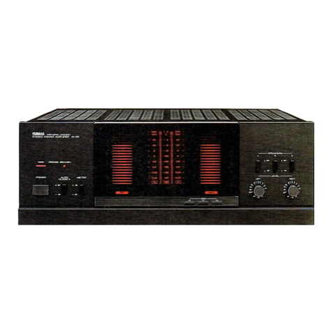
Thank
you
for
purchasing
the
YAMAHA
MX-70
stereo
power
amplifier.
or
0
FE
a
EPA
ฟี
|
e
r
E
6
พ
|
29
qe
=
ve
d
Ey
Dri?
Bs
&
E
ou:
|
í
To
obtain
the
finest
performance
from
your
new
power
amplifier,
please
read
this
manual
carefully,
keeping
it
handy
for
future
reference.
After
you
know
which
PRECAUTIONS
to
take,
the
section
CON-
NECTIONS
will
show
you
how
to
hook
up
the
MX-70
to
your
control
amplifier
and
speakers.
Operation
of
this
power
amplifier
is
explained
under
FRONT
PANEL
CONTROLS
AND
THEIR
FUNCTIONS.
If
you
have
any
trouble,
the
final
section
on
TROUBLESHOOTING
tells
you
what
to
do
before
contacting
your
YAMAHA
dealer.
FA
OES.
1
ฝ
1
็
0
1
PRECAUTIONS
kan
้
้
้
เ
'
2
ler
4
AAA
พ
ด
assisted
5
TROUBLESHOOTING
|...
SE,
SPEGIFICATIONS
ss
u
daidi
T
IMPORTANT:
Please
record
the
serial
number
of
your
unit
in
the
space
below.
Model:
MX-70
Serial
No.:
WM
Hyperbolic
Conversion
Amplification
Circuit
EB
Advanced
Power
Supply
(APS)
Circuitry
=E
Three-Pair
Speaker
Support
ณี
|
LCD
(Liquid
Crystal
Display)
Power
Level
Meters
=
Overload
Protection
Circuitry
Hyperbolic
Conversion
Amplification
Circuit
This
new
kind
of
circuitry,
developed
by
Yamaha,
eliminates
the
only
serious
drawback
of
previous
Class
A
operation
amplifiers.
These
had
to
switch
to
non-linear
class
AB
operation
above
a
certain
load
current,
causing
a
slight
deterioration
in
the
otherwise
excellent
sound
quality.
The
new
Hyperbolic
Conversion
Amplification
Circuit
does
away
with
this
problem,
allowing
your
Yamaha
MX-70
to
deliver
superior
performance
constantly,
without
switching
or
cut-off,
over
its
entire
power
range.
Advanced
Power
Supply
Circuitry
(APS)
An
amplifier
is
only
as
good
as
its
power
supply
—
this
simple
truth
has
prompted
Yamaha
to
develop
the
APS
circuitry
incorporated
in
your
new
MX-70.
The
problem
with
conventional
power
sources
was
their
tendency
to
produce
pronounced
voltage
ripples
during
medium
to
large
amplitude
music
signals,
particularly
under
low
impedance
loads,
together
with
voltage
fluctuations
in
the
power
transistors.
APS
solves
this
problem
by
providing
an
active
power
source
that
|
ensures
stable
voltage
in
the
final
transistor
stage
under
all
operating
conditions,
thus
greatly
improving
power
supply
to
the
amplifier.
PRECAUTIONS
|
Keep
this
manual
in
a
sale
war
for
futura
reference.
_
LOCATION
_
-
El
Relocation
Before
moving
your
amplifier,
be
sure
to
-
unplug
the
power
cord
and
remove
all
other
connecting
cables.
Avoid
0
your
MX-70
in
direct
TT
or
close
to
a
source
of
heat.
Also
avoid
lo-
cations
in
which
the
device
is
likely
to
be
subjected
to
excessive
dust,
cold
or
mois-
ture.
VENTILATION
_
The
openings
on
the
cabinet
ensure
ha
ventilation
of
the
amplifier.
lf
these
openings
are
obstructed,
the
temperature
inside
the
cabinet
will
rise
rapidly
and
eventually
damage
the
circuits.
Therefore,
avoid
plac-
ing
objects
against
these
openings
and
do
not
install
your
amplifier
in
a
place
such
that
the
flow
of
air
through
the
ventilation
openings
could
be
impeded.
=|
Power
cord
When
removing
the
power
plug
from
the
wall
outlet,
always
pull
directly
on
the
plug.
Never
yank
the
cord
as
this
may
result
in
damage
to
the
cord
and
possibly
a
short-circuit.
If
you
do
not
intend
to
use
this
unit
for
an
extended
period
of
time,
it
is
advisable
to
unplug
the
power
cord.
HH
Switches
and
knobs
void
applying
excessive
force
to
the
switches
and
knobs.
E
Troubleshooting
Chart
Consultthe
Troubleshooting
Chartfor
advice
on
the
common
operation
errors
before
concluding
that
your
amplifier
is
faulty.
E
Servicing
Do
not
open
the
cabinet
or
attempt
to
make
repairs
by
yourself,
as
this
may
aggravate
the
damage
and
expose
you
to
an
electrical
shock.
Æ
Object
and
liquid
entry
See
to
itthat
foreign
objects
or
spilled
liquids
do
not
enter
inside
the
cabinet.
Should
this
case
arise,
consult
your
YAMAHA
dealer.
|
Wipe
off
dust
with
a
dry
soft
cloth.
To
remove
dirt
or
fingermarks,
use
a
soft
damp
cloth
then
dry
immediately
with
a
clean
cloth.
Do
not
use
alcohol,
thinners
or
other
chemical
solvents
since
they
may
damage
the
finish
or
remove
the
panel
lettering.
|
Do
not
use
any
aerosol
sprays
near
this unit
as
these
products
can
easily
get
into
the
unit
and
damage
the
circuitry.
Special
instructions
for
the
U.K.
THE
WIRES
IN
THE
MAINS
LEAD
ARE
COLOURED
IN
ACCORDANCE
WITH
THE
FOLLOWING
CODE:
Blue:
NEUTRAL
Brown:
LIVE
As
the
colours
of
the
wires
in
the
mains
|
lead
ofthis
apparatus
may
not
corresponc
with
the
coloured
markings
identifying
the
terminals
in
your
plug,
proceed
as
follows
The
wire
which
is
coloured
BLUE
must
be
connected
to
the
terminal
which
is
markec
with
the
letter
N
or
coloured
BLACK.
The
wire
which
is
coloured
BROWN
must
be
connected
to
the
terminal
which
is
markec
with
the
letter
L
or
coloured
RED.
FRONT
PANEL
ILLUSTRATION
ABBILDUNG
DER
VORDERSEITE
-ILLUSTRAZIONE
DEL
PANNELLO
ANTERIORE
ILLUSTRATION
DU
PANNEAU
AVANT
ILLUSTRATIONEN
PÅ
FRAMSIDAN
|
—
800
===
Pruz
๑
—
|
—
200
SEE
o
SEE
20m
—
YAMAHA
natura
souno
ipo
er
en
STEREO
POWER
AMPLIFIER
MX-70
--
æ
SS
eg
-EE
e
—
'
—s
se
--
==:
58
=
-20
=
2
—
—
as
=
-25
=
os
—
—
Oe
—
=30
=
a2
—
—
008
-—=—
88
==
ans
—
—
ace
SE
=42
=
oue
—
;
~~
Dans
—
==
000
—
ป
ลุ
ค
LEVEL
Il]
SPEAKERS
l
E
p
8
=
4
ว
E
c
10
,
‘
3
PA
i
;
x
fas
ho
เพ
ส
ต
ต
แล
ม
ด
15
|
UFF
&
OFF
a
DEF
Pe
ON
เอะ
ON
=
aN
๐
๐
-gü
D
Hyperbolic
Conversion
Amplification
Circuit
(5)
LOAD
selectors:
These
three
switches
let
you
adjust
the
peak
|
The
Front
Panel
illustration
is
provided
on
page
3.
|
.
GD
POWER
switch
and
indicator:
Pressing
this
switch
turns
power
on,
causing
the
POWER
indicator
to
light.
To
turn
the
unit
off,
press
again.
@
SPEAKERS
selectors:
Allow
you
to
select
any
of
the
speaker
pairs
connected
to
the
A,
B
and/or
C
terminals
by
pushing
the
ap-
propriate
switch(es)
to
the
ON
position.
NOTE:
___—_—
—çć—
lf
speakers
are
connected
to
terminals
B,
but
not
to
terminals
C,
be
sure
to
press
only
the
B
SPEAKERS
selector
when
listening
via
pair
B.
Pushing
in
selector
C
as
well
will
cut
off
the
sound
from
pair
B
since
B
and
C
are
connected
in
series.
(The
same
holds
true
if
speakers
are
connected
to
C
and
selector
B
is
pressed.)
€)
PROTECTION
indicator:
Lights
for
several
seconds
after
power
-
is
turned
on,
showing
that
the
internal
protection
circuitry
is
currently
activated.
This
mutes
the
output
signal
to
the
speakers,
preventing
the
loud
noise
otherwise
heard
when
switching
on
the
amplifier.
E)
METER
switch:
Switches
the
power
peak
meter
OFF.
(This
power
display
is
not
illuminated
when
the
METER
switch
is
pressed
in.)
©
Power
peak
meter:
indicates
the
power
output
on
a
logarithmically
compressed
scale
from
0.002
to
600 watts
(—
50
to
+
5dB),
in-
dependently
for
the
left
and
right
output
channels.
Readings
are
accurate
for
the
load
determined
by
the
LOAD
selectors.
power
display
according
to
the
speaker
load
impedance.
Whe
using
more
than
one
pair
of
speakers
at
the
same
time,
you
cé
=
work
out
their
combined
impedance
with
the
following
formula
where
X
and
Y
are
the
impedance
values
of
each
speaker
pai
1)
2
pairs
in
parallel
(A+B
or
A+C)
(Xx
Y)
/
(X
+
Y)
=
combined
impedance
Example
for
2
pairs
of
8
ohm
speakers:
(8x8)/(8
+
8)
=
4ohms
2)
2
pairs
in
series
(B+C)
X
+
Y
=
combined
impedance
3)
3
pairs
(A+B+C)
~
Same
formula
as
1),
with
A=X
and
(B+C)=
if
the
combined
impedance
does
not
correspond
exactly
to
or
of
the
three
LOAD
seitings,
select
the
closest
one.
@
LEFT
and
RIGHT
LEVEL
controls:
These
give
you
independent
control
over
the
power
output
levels
to
the
L
and
R
speakers
This
allows
you
to
preset
speaker
balance
for
optimum
stere
imaging.
These
controls
can
also
serve
to
protect
speakers
with
power
handling
capacity
lower
than
this
amplifier’s
rate
output.
|
|
The
connection
diagram
is
provided
on
page
32.
|
@
CONTROL
AMPLIFIER
(Y
SPEAKERS
A
($)
SPEAKERS
B
E)
SPEAKERS
C
Make
sure
the
left
(L)
and
right
(R)
channels
are
connected
consist-
ently
between
components.
NOTE:
ee
Before
making
or
altering
any
of
the
connections
described
below,
be
sure
to
turn
off
the
power
of
the
MX-70.
Making
sure
that
the
contro!
amplifier
is
also
turned
off,
connect
the
outputjacks
of
your
control
amplifier
to
the
corresponding
INPUT
jacks
on
the
rear
panel
of
this
unit.
Always
check
that
a)
the
RCA
plugs
of
the
connecting
cord
are
clean,
b)
the
left
and
right
channels
of
both
units
correspond,
.
c)
connections
are
secure,
and
d)
both
units
are
properly
grounded.
The
MX-70
can
drive
up
to
three
pairs
of
speakers
(A,
Band
C}
at
the
same
time.
Those
connected
to
terminals
A
are
in
parallel
with
pairs
B
and
C,
which
are
in
series.
The
following
table
shows
the
minimum
load
impedances
per
speaker
for
all
possible
connections.
Number
of
=
MX-70
Minimum
speaker
speakers
terminals
load
impedance
1
pair
3
pairs
A+B+C
0
A:
8ohms
B,C:
4
ohms
Be
sure
to
use
only
speakers
within
the
rated
impedance
range
and
with
adequate
power
handling
capacity.
Driving
speakers
with
ex-
tremely
low
impedance
(or
several
low-impedance
pairs
simul-
taneously)
at
continuous
full
power
may
cause
the
protection
circuit
to
activate.
When
connecting
the
speaker
cords,
observe
the
“+”
and
“—”
markings
on
the
backs
of
the
speakers
and
MX-70.
If
the
“+”
and
“—”
polarities
are
reversed,
the
sound
will
be
unnatural
and
lack
bass.
Speaker
cords
should
be
cut
as
short
as
possible.
Do
not
coil
up
excess
cord
or
bundle
it
with
cables
from
other
components.
2
pairs
in
parallel
Strip
approximately
10
mm
(3/8”)
insulation
from
the
ends
of
the
speaker
cords
and
connect
them
as
explained
on
the
next
page:
A.Light-gauge
Speaker
cords
|
Partly
unscrew
the
plastic
wire
holders.
Insert
the
stripped
ends
of
the
speaker
cords
as
shown
and
retighten
the
holders.
RED
for
(+)
BLACK
for
(—)
|
B.Heavy-gauge
speaker
cords
First,
unscrew
and
remove
the
plastic
wire
holders.
Insert
the
stripped
ends
of
the
speaker
cords
into
the
holders
until
they
protrude
on
the
other
side.
Splay
the
strands
as
shown,
then
screw
the
wire
holders
back
Before
assuming
that
your
amplifier
is
faulty,
check
the
following
list.
If
you
still
have
any
doubts
or
questions,
contact
your
nearest
YAMAHA
dealer.
Lo
Symptom
7
0
0
2703.
๒
0 อ
๐
๐
ร
น
5
๒
nn
er
N
Remedy
O
ee
No
power
even
when
the
POWER
switch
is
ON.
|
@
The
power
cord
is
nat
plugged
in
securely.
@
Plug
in
securely.
| |
No
sound
is
heard
from
the
left
and/or
right
®
The
speaker
cords
are
not
properly
connected.
@
Check
speaker
connections
and
correct
them.
speaker(s).
@
Either
or
both
LEVEL
controls
are
set
to
—
oodB.
®
Adjust
the
appropriate
LEVEL
control(s).
@
The
cords
from
the
control
amplifier
are
not
secure.
|
@
Connect
them
securely.
@
The
control
amp’s
balance
is
set
to
the
extreme
left
@
Adjust
the
control
amp’s
balance
control.
|
or
right.
| |
The
sound
ceases
suddenly,
and
the
®
The
speaker
protection
circuit
has
activated.
®
Turn
power
OFF,
then
ON
again
to
reset
the
speaker
protection
PROTECTION
indicator
is
lit.
circuit.
Also
see
CONNECTING
SPEAKERS
on
p.
5.
®
There
is
a
malfunction
in
the
amplifier.
®
Consult
your
YAMAHA
dealer.
Unnatural
sound
lacking
bass.
®
The
speaker
polarities
are
reversed.
®
Connect
the
speaker
wires
with
the
correct
+
and
—
polarity.
Minimum
RMS
Output
Power
Per
Channel
intermodulation
Distortion
|
20Hz
~
20kHz
0.003%
THD,
8
ohms
.
170W
Rated
Output/8
onms
0.003%
0.007%
THD,
6
ohms
0
Signal
to
Noise
Ratio
(IHF-A-Network)
|
0
A
20
MAIN
IN
(shorted)
124dB.
Dynamic
Power
Per
Channel
MAIN
IN
(5.1
kQ
terminated)
120d8
(by
IHF
Dynamic
Headroom
measuring
method)
Residual
Noise
(IHF-A-Network)
21uV
8
ohms
I
270W
RR
6
ohms
330W
0
Channel
Separation
4
ohms
440W
Input
shorted,
terminated,
2
ohms
570W
1kHz/10kHz
89dB/72dB
1
ohms
|
600W
Power
Supply
DIN
Standard
Output
Power
Par
Channel
|
|
|
Europe
AC220V,
50Hz
1kHz,
1%
THD,
4
ohms
250W
|
U.K.
AC240V,
50Hz
Power
Band
Width
Power
Consumption
1,150W
0.03%
THD
85W,
8
ohms
10Hz
-
60kHz
Dimentions
(W
x
H
x
D)
|
435
x
165
x
425mm
Damping
Band
Width
|
(17-1/8”
x
6-1/2”
x
16-47/64”)
1kHz,
8
ohms
90
Weight
14.5kg
input
Sensitivity/impedance
|
MAIN
IN
| -
1.32V/60kQ
Specifications
subject
to
change
without
notice.
Frequency
Response
|
(20Hz
~
20kHz)
+0,
—0.2dB
Total
Harmonie
Distortions
(20Hz
~
20kHz)
MAIN
IN
to
Sp
Out,
85W/8Q
0.003%

Other manuals for MX-70

2

Other Yamaha Amplifier manuals

Yamaha XMV8280-D User manual

Yamaha

Yamaha XMV8280-D User manual

Yamaha XP7000 User manual

Yamaha

Yamaha XP7000 User manual

Yamaha T3n User manual

Yamaha

Yamaha T3n User manual

Yamaha Electone C-60 User manual

Yamaha

Yamaha Electone C-60 User manual

Yamaha PC1002 User manual

Yamaha

Yamaha PC1002 User manual

Yamaha M-45 User manual

Yamaha

Yamaha M-45 User manual

Yamaha PC3300N User manual

Yamaha

Yamaha PC3300N User manual

Yamaha DSP-A5 User manual

Yamaha

Yamaha DSP-A5 User manual

Yamaha AX-892 User manual

Yamaha

Yamaha AX-892 User manual

Yamaha AST-A10 User manual

Yamaha

Yamaha AST-A10 User manual

Yamaha THR5A User manual

Yamaha

Yamaha THR5A User manual

Yamaha CA-610 II User manual

Yamaha

Yamaha CA-610 II User manual

Yamaha MX-A5200 User manual

Yamaha

Yamaha MX-A5200 User manual

Yamaha DSP-AX1/RX-V1 User manual

Yamaha

Yamaha DSP-AX1/RX-V1 User manual

Yamaha MX-630 User manual

Yamaha

Yamaha MX-630 User manual

Yamaha AS1000 - Amplifier User manual

Yamaha

Yamaha AS1000 - Amplifier User manual

Yamaha A-S700 - Amplifier User manual

Yamaha

Yamaha A-S700 - Amplifier User manual

Yamaha PA2120 User manual

Yamaha

Yamaha PA2120 User manual

Yamaha E580 User manual

Yamaha

Yamaha E580 User manual

Yamaha DSP-Z9 User manual

Yamaha

Yamaha DSP-Z9 User manual

Yamaha M-2 User manual

Yamaha

Yamaha M-2 User manual

Yamaha A-S501 User manual

Yamaha

Yamaha A-S501 User manual

Yamaha PC1002 User manual

Yamaha

Yamaha PC1002 User manual

Yamaha MX-50 User manual

Yamaha

Yamaha MX-50 User manual

Popular Amplifier manuals by other brands

Dekolink Wireless MW-CBDA-SMR-800-900-1W80 Installation and operating instructions

Dekolink Wireless

Dekolink Wireless MW-CBDA-SMR-800-900-1W80 Installation and operating instructions

Peavey IPS 800 operating instructions

Peavey

Peavey IPS 800 operating instructions

Extron electronics MPA 152 Plus user guide

Extron electronics

Extron electronics MPA 152 Plus user guide

Terra SA51 user manual

Terra

Terra SA51 user manual

Sure Electronics IRS2092 user guide

Sure Electronics

Sure Electronics IRS2092 user guide

McIntosh MC2KW owner's manual

McIntosh

McIntosh MC2KW owner's manual

Fishman Prefix Pro installation guide

Fishman

Fishman Prefix Pro installation guide

Alpine PDX-V9GC owner's manual

Alpine

Alpine PDX-V9GC owner's manual

Crate GX-60C owner's manual

Crate

Crate GX-60C owner's manual

Rogue Audio Tempest Vacuum Tube Integrated Amplifier owner's manual

Rogue Audio

Rogue Audio Tempest Vacuum Tube Integrated Amplifier owner's manual

Channel D Lino C 3.0 Installation and use manual

Channel D

Channel D Lino C 3.0 Installation and use manual

Gold Note P-1000 owner's manual

Gold Note

Gold Note P-1000 owner's manual

Schwaiger GHSA0100 USER GUIDE AND SAFETY INSTRUCTIONS

Schwaiger

Schwaiger GHSA0100 USER GUIDE AND SAFETY INSTRUCTIONS

Crestron CNAMPX-12X60 Operation guide

Crestron

Crestron CNAMPX-12X60 Operation guide

Orion Cobalt CO600.2 owner's manual

Orion

Orion Cobalt CO600.2 owner's manual

Benchmark DAC1 HDR instruction manual

Benchmark

Benchmark DAC1 HDR instruction manual

Korg Nu:Tekt HA-S owner's manual

Korg

Korg Nu:Tekt HA-S owner's manual

World Video Sales MicroImage Video Systems VDA206 Operation manual

World Video Sales

World Video Sales MicroImage Video Systems VDA206 Operation manual

manuals.online logo
manuals.online logoBrands
  • About & Mission
  • Contact us
  • Privacy Policy
  • Terms and Conditions

Copyright 2025 Manuals.Online. All Rights Reserved.