manuals.online logo
Brands
  1. Home
  2. •
  3. Brands
  4. •
  5. Yamaha
  6. •
  7. Control System
  8. •
  9. Yamaha Fl 3.58 User manual

Yamaha Fl 3.58 User manual

@YAMAHA
,U
U
@
@
@
Fl 3.58
Fl 5C
F20B
REMOTE CONTROL ATTACHMENT KIT
INSTALLATION MANUAL
MANUEL D'INSTALLATION DU KIT DE MISE EN PLACE
DE COMMANDE A DISTANCE
MANUAL DE INSTALACION DEL JUEGO ACCESORIO
DE CONTROL REMOTO
6AF-2819K-90
@
PREPARATION
TILLER HANDLE AND FRICTION PLATE REMOVAL
/ _--^»
/ -.--// a-g-
<,'' { l-z'%
\ \-//-\
V\\- \
11,W
ro--3
18
No. Part name Q'ty Remarks
1
2
3
4
5
6
7
I
I
10
11
12
Throttle cable
Engine shut-off switch lead
Bolt
Bolt
Steering bracket cover
Screw
Bolt
Holder
Shift lever
Shift link rod
Washer
Clip
2
1
1
4
1
1
1
1
1
1
1
1
M6x15mm
M6x18mm
aGx19 mm
M6xlBmm
l-cE- a
& @-r>-,
12 tt ["(t*,
rcgy'-
\
/1
N1,fi 21
r o--€
I\4,
No. Part name Q'ty Remarks
13
14
15
16
17
18
19
20
21
22
23
24
25
26
Bolt
Collar
Wave washer
Bolt
Bolt
Friction plate
Washer
Wave washer
Bushing
Grommet
Tiller handle assembly
Bushing
Tiller handle bracket cover
Bolt
1
1
1
2
2
1
2
2
1
1
,1
1
1
2
M6 x 40 nrm
M5 x 1B mm
MB x 22 rnm
M6x55mm
@
31
.,M
* @r>,
'?rtD>
No. Part name Q',ty Remarks
27
28
29
30
31
32
33
34
35
JO
37
Screw
Cover
Bolt
Retaining plate
Grommet
Grommet
Bolt
Screw
Bracket
Adapter
Plastic tie
2
1
2
1
1
1
2
2
1
1
1
M6x30mm
M6x10mm
sGx20mm
Noi reusable
I
FRICTION PLATE REMOVAL
1. Remove:
. Bolts @ and @
. Friction plate assembly @
TIP:
Before removing the bolts @, turn the out-
board motor completely to porl or starboard.
TILLER HANDLE REMOVAL
1. Remove:
. Steering bracket cover @
2. Remove:
' CliP @
. Washer @
. Shift lever §
. Grommet 3
3. Bemove:
. Engine shut-off switch lead O
TIP:
Disconnect the engine shut-off switch connec-
tor (white lead) and remove it from the holders.
I Electric stafter model
E Manualstarter model
11
@
4. Remove:
. Throttle cables @
. Plastic tie (not reusable) @
5. Remove:
. Tiller handle assembly @
6. Remove:
. Retaning plate @
. Bracket @
. Grommet @
Xl
E
l'
lr
ir
ij
3
I
i
r
i
I
I
t' i:
Iti
I ',i,
t'
13
@
INSTALLATION
REMOTE CONTROL ATTACHMENT KIT INSTALLATION
8.0 N . m (0.82 kof ' m, 5.9 ft '
,': 8.0 N . m (0.82 ksf . m, 5.9 ft . lb
4.0 N. m (0.41 kqf . m, 3.0ft . lb
2.0 N . m (0.20 kof . m, 1.5 ft. lb)
4.0 N . m (0.41 kqf . m, 3.0 ft .
--'
-<"@;
,/fi/-2,
"rrfr
§
31'
No. Part name Q'ty Remarks
1
2
3
4
5
6
7
I
9
10
11
12
Remote control cable joint
Bolt
Clip
Bolt
Retaining plate
Grommet
Grommet
Bolt
Cable guide
Bolt
Steering bracket cover
Screw
2
1
2
2
1
1
1
1
1
4
1
1
M6x15mm
M6x30mm
M6x20mm
MGxlBmm
aGx19 mm
15
8.0 N . m (0.82 kgf . m, 5.9 ft. lb)
4.0 N . m (0.41 kqf . m, 3.0 ft . lb
2.0 N . m (0.20 kqf . m, 1.5 ft . lb W" T /But$
\,J 7 ,u q El
,;i @y'«
')/ tz\ I 't- ll @) fl )§3''s
W{ - -<, +- 4:"1.r.[, . dffi'
)4;WW
§,, g >)F,3
I ) .-t ,,/
t1' @t
\W< q?1
- --ts, .&22 i- ^
u-700 33
24
25
4.0 N . m (0.41 kqf . m, 3.0 ft . lb
F
31'
8.0 N . m (0.82 kgf . m, 5.9 ft. lb
No. Part name Q',ty Remarks
13
14
15
16
17
18
19
20
21
22
23
24
25
26
Bolt
Screw
Adapter
Bracket
Grommet
Spring pin
Cable clamp
Blind plug
cap
Bolt
Self-locking nut
Hook
Self-locking nut
Steering link rod
2
2
1
1
1
1
1
1
1
1
2
1
1
1
M6x10mm
aGx2Omm
M8x25mm
17
@
8.0 N ' m (0.82 ksf . m, 5.9 ft . lb
4.0 N . m (0.41 kgf . m, 3.0 ft . lb)
2.0 N . m (0.20 kqf . m, 1.5 ft .
4.0 N . m (0.41 ksf . m, 3.0 ft . lb
10
12
,Y t18.0 N . m1.84 kqf ' m, 13.3 ft . lb
§
31'
8.0 N' m (0.82 ksf ' m, 5.9ft . lb)
No. Part name Q',ty Remarks
27
28
29
30
31
32
33
34
Washer
cap
O-ring
Socket cord assembly
Plastic tie
Plastic tie
Bolt
Switch bracket
2
1
1
1
2
1
2
1
Not reusable
M6x30mm
19
@
REMOTE CONTROL ATTACH M ENT
KIT INSTALLATION
1. lnstall:
. HookO
. Bolt @
Bolt:
18.0N.m
(1.84 kgf . m, 13.3 ft.lb)
2. lnstall:
. Steering link rod @
. Nut@
Nut:
18.0N.m
(1.84 kgf . m, 13.3 ft . lb)
3. lnstall:
. Grommet O
. Grommet @
. Steering bracket cover @
. Bolt O
Bolt:
4.0 N . m (0.41 kgf . m, 3.0 ft.lb)
4. lnstall:
. Switch bracket @
. Bolt O
\-
?-r/1>
\' Bolt:
8.0 N . m (0.82 kgf . m, 5.9 ft. !b)
5. lnstall:
. Adapter O
. Screw O
. Bracket O
. Bolt @
Bolt:
2.0 N . m (0.20 kgf . m, 1.5 ft . lb)
--<
..' I
,=-O-
21
r-
6. lnstall:
. Cable clamp @
. pin spring @
. Grommet @
T.Prepar:
. Socket cord assembly O
TIP:
Making sure not to damage the leads, cut
away 160 mm (6.3 in) of the rubber sheath @
in order to connect the connectors.
I
!'
':l ,,
lli
J i!
23
10. lnstall:
. Cable gulde @
. Bolt @
. Grommet @
. Shift cable @
. Throttle cable @
Bolt:
10.0 N . m ('t.02 kgf . m,7.4ft. lb)
T!P:
. The hole in the bottom cowling for the bolt @
is not threaded. therefore. to ensure that the
hole is threaded properly. be sure to keep
the bolt upright when tightening it.
. Install the throttle cable I io cable guide @.
11. Adjust:
. Shift cable joint position
t
Adjustment procedure:
. Set the remoie control lever and shift rod
lever joint 3 to :ihe neutral position.
. lnstall the cabre joint @ onto the shift
cable. and the^ adjust the position of the
joint untii its nole @ is aligned with the set
pin 6 on the shift rod lever joint @.
The shift cable joint must be screwed in
a minimum of 8.0 mm (0.31 in) @.
Connect the shift cable joint @, install the
clip Q. and ihen tighten the locknut @.
Check thai the gear shift operates
smoothly rvhen the remote control lever is
shifted from the neutral position to forward
or reverse.
29

This manual suits for next models

2

Other Yamaha Control System manuals

Yamaha BB714BS User manual

Yamaha

Yamaha BB714BS User manual

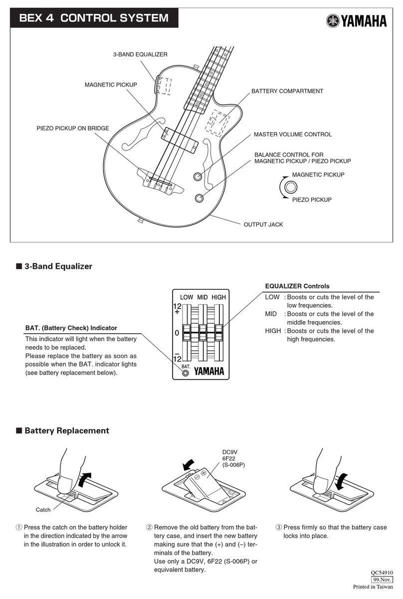
Yamaha BEX 4 User manual

Yamaha

Yamaha BEX 4 User manual

Yamaha RGX-420/S/-D6/DZ User manual

Yamaha

Yamaha RGX-420/S/-D6/DZ User manual

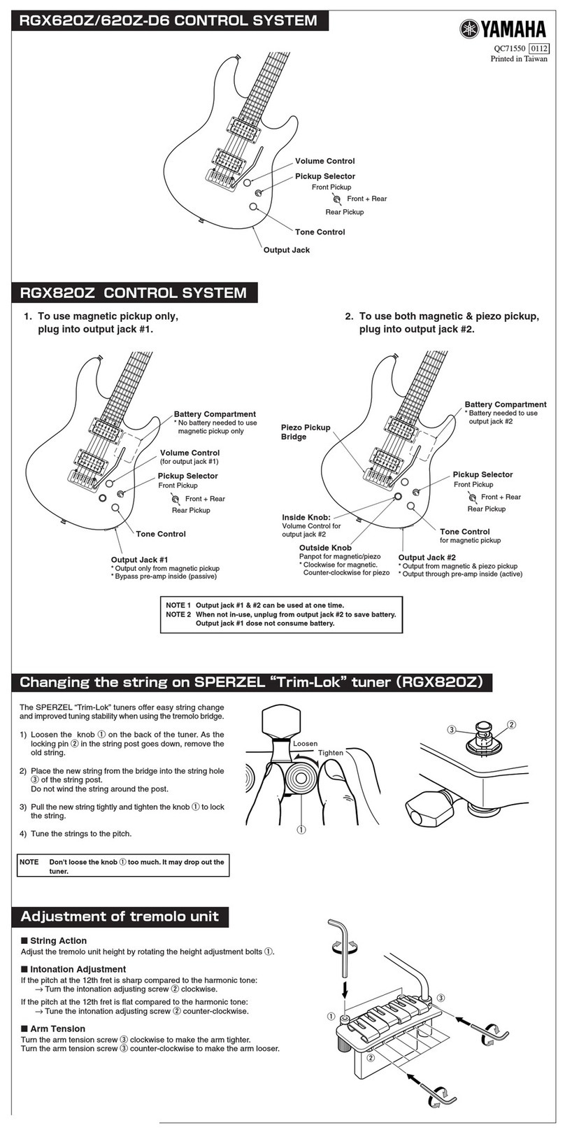
Yamaha RGX620Z User manual

Yamaha

Yamaha RGX620Z User manual

Yamaha AES-FG User manual

Yamaha

Yamaha AES-FG User manual

Yamaha BB NE2 User manual

Yamaha

Yamaha BB NE2 User manual

Yamaha AES-820 User manual

Yamaha

Yamaha AES-820 User manual

Yamaha BB 604 User manual

Yamaha

Yamaha BB 604 User manual

Popular Control System manuals by other brands

Siemens SIMATIC PCS 7 Programming manual

Siemens

Siemens SIMATIC PCS 7 Programming manual

Modine Manufacturing 5H104766 quick start guide

Modine Manufacturing

Modine Manufacturing 5H104766 quick start guide

Raven PRECISION AUTOBOOM G1 Calibration and Operator's Manual

Raven

Raven PRECISION AUTOBOOM G1 Calibration and Operator's Manual

Skytech RCAF-LMF/RD Installation and operation instructions

Skytech

Skytech RCAF-LMF/RD Installation and operation instructions

Vaillant VR 940f installation instructions

Vaillant

Vaillant VR 940f installation instructions

CYBELEC CybTouch 12 user manual

CYBELEC

CYBELEC CybTouch 12 user manual

Gate Titan user manual

Gate

Gate Titan user manual

iAIRE ultraDRY manual

iAIRE

iAIRE ultraDRY manual

Hi-Tec Laser 4 Introduction manual

Hi-Tec

Hi-Tec Laser 4 Introduction manual

Astral Pool 27818 Installation and maintenance manual

Astral Pool

Astral Pool 27818 Installation and maintenance manual

Waterco Aquamaster Installation and operation manual

Waterco

Waterco Aquamaster Installation and operation manual

WatchDog 3452H product manual

WatchDog

WatchDog 3452H product manual

Sel SEL-451-5 manual

Sel

Sel SEL-451-5 manual

Aqua Control C4115 manual

Aqua Control

Aqua Control C4115 manual

Pro-tec Algo-Tec 6500 user manual

Pro-tec

Pro-tec Algo-Tec 6500 user manual

Ansul AUTOPULSE 442R Inspection, Operation, and Maintenance Manual

Ansul

Ansul AUTOPULSE 442R Inspection, Operation, and Maintenance Manual

btsr SMART WARP operating manual

btsr

btsr SMART WARP operating manual

Tektronix Aurora user manual

Tektronix

Tektronix Aurora user manual

manuals.online logo
manuals.online logoBrands
  • About & Mission
  • Contact us
  • Privacy Policy
  • Terms and Conditions

Copyright 2025 Manuals.Online. All Rights Reserved.