Yamaha S20 Operating and installation instructions

For Service Engineer
Service Information
SI1604009E-002= S20, S10, M20, M10 and D10 installation procedures
1/34
MACHINE TYPE : S20, S10, M20, M10 and D10
CLASSIFICATION : Installation / Maintenance / TIPS
REFERENCE : N/A
S20, S10, M20, M10 and (D10) installation procedures
General description
This document describes the new installation procedures of S20, S10, M20, M10 and D10.
See the “Installation Check Sheet” for the actual working procedures as well.
About this document:
This document is for service engineers and those who have completed the maintenance training.
Make sure to use it under the instruction of those who have completed the maintenance training or a
YAMAHA serviceman.
YAMAHA is not responsible for any problems caused by the misuse of the document.
This document contains the method to edit the system data that affects the customer’s machine condition.
Make sure to thoroughly understand the contents of the document, and perform the adjustments on your own
responsibility.
About the safety:
Strictly follow the safety precautions in the “Safety” section in the “Operation Manual”.
Disclaimers:
This document contains the preliminary information subject to change in the future.
The information contained in this document represents the current view of YAMAHA on the issues discussed as of
the date of issuance. As YAMAHA must respond to changing market conditions, it should not be interpreted to be
a commitment on the part of YAMAHA, and YAMAHA cannot guarantee the accuracy of any information
presented after the date of issuance.
This document is provided for information purposes only, and it is provided without any warranties, either express
or implied.
It is the responsibility of the user to comply with all applicable copyright laws. Without limiting the rights under
copyright, no part of this document may be reproduced, stored in or introduced into a retrieval system, or
transmitted in any form or by any means (electronic, mechanical, photocopying, recording, or otherwise), or for
any purpose, without the written permission of YAMAHA.
However, this shall not be construed to limit the user’s right granted by Copyright law.
YAMAHA may have patents, patent applications, trademarks, copyrights, or other intellectual property rights
covering subject matter in this document. Except as expressly provided in any written license agreement from
YAMAHA, this document does not give users any license to these patents, trademarks, copyrights, or other
intellectual property.
The names of actual companies and products mentioned in this document may contain the trademarks of their
respective owners.
No: SI1604009E-002
ISSUED DATE: April 12, 2017
REVISED DATE April 04, 2018

For Service Engineer
Service Information
SI1604009E-002= S20, S10, M20, M10 and D10 installation procedures
2/34
Table of contents
1. Machine installation requirements..................................................................................................3
2. Confirmations before shipping........................................................................................................4
3. Carry in machines & equipment and level the machine................................................................5
3.1 Confirmations before carrying-in......................................................................................................5
3.2 Unload the machines and equipment...............................................................................................5
3.3 Carry in machines and equipment ...................................................................................................6
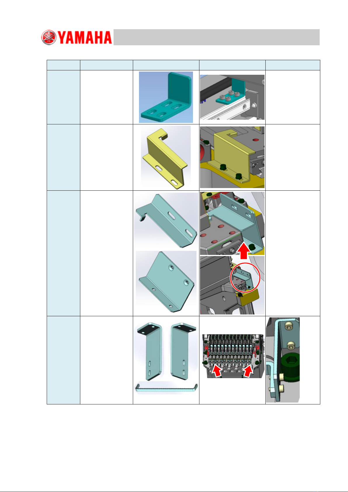
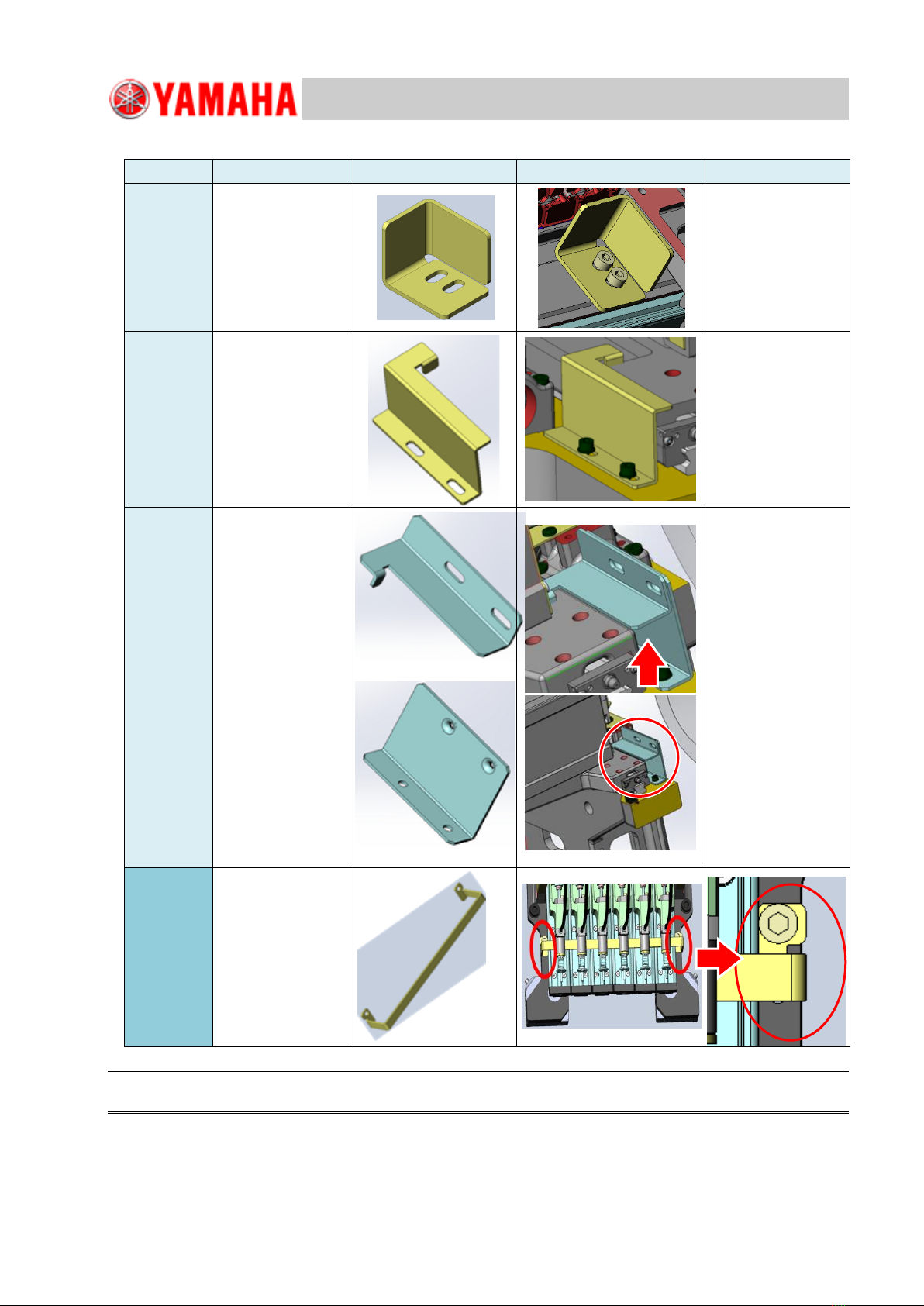
3.4 Remove the shipping brackets.........................................................................................................6
3.5 Preparation before marking............................................................................................................11
3.6 Install the machines temporarily.....................................................................................................12
3.7 Level the machine..........................................................................................................................13
3.7.1 Coarse adjustment..................................................................................................................13
3.7.2 Jack and sliding paper............................................................................................................14
3.7.3 Jack setting positions of the machine.....................................................................................14
3.7.4 Place a jack ............................................................................................................................16
3.7.5 Position the machine ..............................................................................................................17
3.8 Correction and adjustment of levelness.........................................................................................18
3.8.1 Check the X-beam torsion......................................................................................................18
3.8.2 Case if the torsion is large......................................................................................................19
3.9 Lock adjuster bolts and support legs..............................................................................................20
4. Setup after installing the machine.................................................................................................22
4.1 Install accessories..........................................................................................................................22
4.2 Install the LCD monitor and the balancer.......................................................................................22
4.2.1 Previous LCD monitor.............................................................................................................22
4.2.2 Current LCD monitor...............................................................................................................23
4.3 Air and power connection...............................................................................................................24
4.3.1 Connect the air and power to the machine.............................................................................24
4.3.2 Check and adjust the air pressure..........................................................................................25
4.4 Confirm the PCB transfer...............................................................................................................26
5. Reference.........................................................................................................................................27
5.1 Unload the machine by suspending...............................................................................................27
5.2 The effects caused by the slanted floor ............................................................................................28
5.2.1 The material and the load capacity of the floor ......................................................................29
5.3 Condensation on the machine ..........................................................................................................30
5.3.1 The formation process of condensation on the machine..............................................................30
5.3.2 How to prevent condensation from forming on the machine ........................................................32
5.3.3 When condensation occurs...........................................................................................................32
6. Revision history ..............................................................................................................................34

For Service Engineer
Service Information
SI1604009E-002= S20, S10, M20, M10 and D10 installation procedures
3/34
1. Machine installation requirements
Confirm the following machine installation requirements and install the machine where
the following conditions are satisfied.
Air
Item
Detail
Remark
Air pressure
Supply air pressure: 0.45MPa or more
8.5mm ×
12.5mm hose
Condition
・50L / min.A.N.R. (4-head type)
・75L / min.A.N.R. (6-head type)
・140L / min.A.N.R. (12-head type)
Clean air (Removed moisture, oil and dust)
Power supply
Item
Detail
Remark
Power supply
Three-phase alternating current 200 / 208 / 220 /
240 / 380 / 400 / 416 / 440V (+/-10%)
Frequency
50Hz / 60Hz
Power capacity
S10:6.4 KVA S20:6.8 KVA
M10:5.5 KVA M20:5.9 KVA D10:5.5 KVA
D10 =5.5KVA
Power cable (equivalent to VCT 4 × 3.5mm2)
Power supply
connection
Power cable conductor cross-section 3.5mm2or
more
Leakage current
20mA or less
Installation environment requirement
Item
Detail
Remark
Noise
Meeting EN61000-6-2 standard
Humidity
50 ~ 60% (non-condensing)
Temperature
Operation assurance: Within the range from 10 to 35 degrees C
Accuracy assurance : 23+/-2 degrees C
The average over a period of 24
hours does not exceed 30 degrees C
Altitude
1,000m or below above sea level
Floor
The floor must be flat and has the enough strength of enduring
the vibration of the machine during the operation.
Note:
If the machine that is the source of noise locates in the line configuration, do not share
the power supply and the ground wire.
Connect the power supply to the separate lineage from the power distribution panel.
Install the ground wire individually.
Note:
If the strong light from the indoor lightings, the direct sunlight and etc., may enter the machine
due to the machine configuration, note that the lights may adversely affect to the image processing.

For Service Engineer
Service Information
SI1604009E-002= S20, S10, M20, M10 and D10 installation procedures
4/34
2. Confirmations before shipping
When installing and adjusting machines at customers' sites, make sure to gain necessary information
and prepare thoroughly beforehand to avoid troubles.
The typical confirmations are as below.
Time of carry-in the machine
Check the schedule (date and time).
Carry-in location, carry-in route, floor and installation site
Check the required items other than a forklift and hand lifter.
Check that required quantities of curing sheets, plywood panels, and iron plates are prepared.
Line configuration of machines
Check the upstream and downstream machines of the machine to be installed and make sure
that they will not interfere with the monitor, the keyboard and etc.
Prepare the connecting tools for monitor and keyboard if needed.
Check that the signal lines between machines are standard or special order.
Check that LAN connection is prepared. Understand the usage of the database.
The power source and the air supply
Make sure that the customer is informed of the specified capacity of the power source for the
machine.
Make sure that the customer is informed of the specified diameter of the air pipe and its airflow.
Make sure that the schedule for the electric works and the air piping works are set according to
the installation schedule as required.
Weather and temperature on the day of delivering the machine
Condensation may occur on the machine depending on the morning temperature in winter
when carrying it in the installation site.
When the difference between the external temperature and the temperature in the
installation site is over 10 degrees C, condensation may occur on the machine.
If condensation may occur on the machine, prepare the place to temporarily locate the machine.
The equipment and the time to gradually warm up the machine are required on site.
Prepare a thermometer beforehand.
Note:
Regarding the confirmations above, a lot of discrepancies among users, sales personnel and service
engineers occur. Troubles when installing the machine occur repeatedly.
They assume that required items are prepared and fail to confirm. This is the cause of the troubles.
Make sure to confirm by yourself.

For Service Engineer
Service Information
SI1604009E-002= S20, S10, M20, M10 and D10 installation procedures
5/34
3. Carry in machines & equipment and level the machine
3.1 Confirmations before carrying-in
A transport company will bring the machine to the customer’s site by truck, etc.
The followings are the required confirmations before unloading the machines or equipment from a truck.
Make sure there is no damage to the machine.
If any damage, dent or deformation caused during transportation found on the machine, have the
transport company check the situation out, and take some pictures of the damaged part on the spot
as evidence (taking pictures using a cell phone is fine). Also let the customer know immediately to
take proper measures.
Make sure that all the requirements for installing the machine have been delivered to the
installation site.
If the requirements for installing the machine have not been delivered to the installation site, inform the
transport company immediately and have them to ship the items by other truck.
Check the external temperature.
If the external temperature is low, condensation may occur. Explain this to the customer and ask them
to prepare the place to temporarily locate the machine (the difference between the external
temperature and the temperature in the installation site must be 10 degrees C or less).
Rent a stove, etc., and gradually warm up the machine. Carry in the machine after confirming that the
base of the machine temperature rises 5 degrees C.
Caution:
Condensation may occur on the machine when the difference between the external temperature and the base of
the machine temperature is 10 degrees C or more.
Make arrangement with the customer regarding the installation of the machine beforehand.
Make final checks if the installation of the machine, the electric work and the work for air supply are
going to be performed as scheduled, and the safety precautions (as the regulations vary depending
on the customer).
3.2 Unload the machines and equipment
Normally a transport company unloads the machine from a truck using a forklift, etc.
Caution:
When the machine is on a truck, confirm that the supporting legs (locating in the bottom center of S20 and M20)
are raised.
Carry in the machine that was unloaded from a truck to the installation site by operating a transport
equipment such as a hand lifter, etc. Make sure to follow the precautions below.
Precaution when operating a forklift
When the machine is packed, the notice is labelled as shown in the figure below to avoid the fork of the
forklift and the cover of the machine from interfering with each other.
Do not insert the fork into the labelled part as the cover, etc., may be damaged.
See “5.1 Unload the machine by suspending“for unloading the machine operating a unic.
S10, M10
S20, M20

For Service Engineer
Service Information
SI1604009E-002= S20, S10, M20, M10 and D10 installation procedures
6/34
3.3 Carry in machines and equipment
Carry in a machine and necessary equipment with great care to avoid accidents.
Protect the floor to avoid damaging it. (Plastic tiles especially need protection.
Prepare curing sheets.)
When operating lifting equipment such as a hand lifter;
Pay attention to the center of gravity of the machine.
Do not lift it up excessively.
Handle the hand lifter with care.
If damaging the customer’s possessions (the floor, the building, etc.) while carrying in the
machine to the installation site;
Promptly let the customer know and seek for their directions.
Otherwise it may cause a serious problem later on.
Take some pictures of the damage. (Make sure to get the customer’s permission before
doing so.)
Remove plastic wrapping from the machine.
After moving the machine to near the production line or the entrance of the clean room, remove the
plastic wrappings from the machine and the accessories.
3.4 Remove the shipping brackets
See “Checklist for the shipping brackets” for the procedure of removing the shipping brackets
of the machine located temporarily.
Checklist for the shipping brackets of M20, M10 and D10
Axis
Qty
Shipping bracket
Status
Remark
X-axis
1 position
LOCK,X-AXIS
LE6-M220Y-00
BOLT,HEX,SOKET
HEAD
M5 × L10 Qty:2
91312-05010
Y-axis
2 positions
LOCK,Y-AXIS
LE6-M260Y-00
LE6-M260Y-10
BOLT,HEX,SOKET
HEAD
M5 × L10 Qty:4
91312-05010
Z-axis
1 position
LOCK,Z-AXIS
4-head LE6-M710Y-50
6-head LE6-M710Y-60
BOLT,HEX,SOKET
HEAD
M4 × wL15 Qty:2
91312-04015
Brackets vary
depending on the
head configuration.

For Service Engineer
Service Information
SI1604009E-002= S20, S10, M20, M10 and D10 installation procedures
7/34
Checklist for the shipping brackets of S20 and S10 for MT12 HEDS (Z-AXIS BRKT. TYPE A)
Axis
Qty
Shipping bracket
Status
Remark
X-axis
1 position
LOCK,X-AXIS
LF1-M220Y-00
BOLT,HEX,SOKET
HEAD
M4 × L8 Qty:4
91312-04008
Y1-axis
1 position
LOCK,Y-AXIS
LE6-M260Y-00
BOLT,HEX,SOKET
HEAD
M5 × L10 Qty:2
91312-05010
Y2-axis
1 position
LOCK,Y-AXIS
LF3-M220Y-00
BRKT.LOCK
LF3-M220X-00
BOLT,HEX.SOKET
HEAD
M5 × L10 Qty:4
Z-axis
1 position
BRKT,Z-AXIS L
LF3-M7193-00
BRKT,Z-AXIS R
LF3-M7192-00
BRKT,Z-AXIS
BOTTOM
LF3-M7191-00
BOLT,HEX,SOKET
HEAD
M2.5 × L6 Qty:8

For Service Engineer
Service Information
SI1604009E-002= S20, S10, M20, M10 and D10 installation procedures
8/34
Checklist for the shipping brackets of S20 and S10 for MT12 HEDS (Z-AXIS BRKT. TYPE B)
Axis
Qty
Shipping bracket
Status
Remark
X-axis
1 position
LOCK,X-AXIS
LF1-M220Y-00
BOLT,HEX,SOKET
HEAD
M4xL8 Qty:4
91312-04008
Y1-axis
1 position
LOCK,Y-AXIS
LE6-M260Y-00
BOLT,HEX,SOKET
HEAD
M5xL10 Qty:2
91312-05010
Y2-axis
1 position
LOCK,Y-AXIS
LF3-M220Y-00
BRKT.LOCK
LF3-M220X-00
BOLT,HEX.SOKET
HEAD
M5xL10 Qty:4
Z-axis
1 position
BRKT,Z-AXIS
BOTTOM
LF3-M7191-00
BRKT,Z-AXIS
LF3-M7192-01
Qty:2
BOLT,HEX SOCKET
HEAD M2.5xL6 Qty:4
BOLT,HEX,SOKET
HEAD
M5xL10 Qty:4

For Service Engineer
Service Information
SI1604009E-002= S20, S10, M20, M10 and D10 installation procedures
9/34
Checklist for the shipping brackets of S20 and S10 for MT12 HEDS (Z-AXIS BRKT. TYPE C)
Axis
Qty
Shipping bracket
Status
Remark
X-axis
1 position
LOCK,X-AXIS
LF1-M220Y-00
BOLT,HEX,SOKET
HEAD
M4xL8 Qty:4
91312-04008
Y1-axis
1 position
LOCK,Y-AXIS
LE6-M260Y-00
BOLT,HEX,SOKET
HEAD
M5xL10 Qty:2
91312-05010
Y2-axis
1 position
LOCK,Y-AXIS
LF3-M220Y-00
BRKT.LOCK
LF3-M220X-00
BOLT,HEX.SOKET
HEAD
M5xL10 Qty:4
Z-axis
1 position
BRKT,Z-AXIS
BOTTOM
LF3-M7191-10
BRKT,Z-AXIS
LF3-M7192-01
Qty:2
BOLT,HEX SOCKET
HEAD M2.5xL6 Qty:4
BOLT,HEX,SOKET
HEAD
M5xL10 Qty:4

For Service Engineer
Service Information
SI1604009E-002= S20, S10, M20, M10 and D10 installation procedures
10/34
Checklist for the shipping brackets of S20 and S10 for MT6 HEDS
Axis
Qty
Shipping bracket
Status
Remark
X-axis
1 position
LOCK,X-AXIS
LF3-M220W-00
BOLT,HEX,SOKET
HEAD
M5xL8 Qty:2
91312-05008
Y1-axis
1 position
LOCK,Y-AXIS
LE6-M260Y-00
BOLT,HEX,SOKET
HEAD
M5xL10 Qty:2
91312-05010
Y2-axis
1 position
LOCK,Y-AXIS
LF3-M220Y-00
BRKT.LOCK
LF3-M220X-00
BOLT,HEX.SOKET
HEAD
M5xL10 Qty:4
91312-05010
Z-axis
1 position
LOCK,Z-AXIS
LF3-M740Y-00
BOLT,HEX,SOKET
HEAD
M5xL10 Qty:2
91312-05010
Caution:
Keep shipping brackets as they are required for the next shipping.

For Service Engineer
Service Information
SI1604009E-002= S20, S10, M20, M10 and D10 installation procedures
11/34
3.5 Preparation before marking
When installing several machines, it is required to install the reference side conveyor correctly
on the marking line and the PCB to be transferred flow smoothly from the top machine to the
last machine.
It is also required to narrow the space between machines as much as possible and reduce
the transferring loss.
This is generally called “marking”.
Required tools
Level vial : At least 2 pcs
PCB for marking : At least 2 pcs
Dedicated jig PCB : (Required when connecting our machine to other manufacturer
machines)
Steel ruler : 1m or 60cm steel ruler (If not having them, approx. 3m metal tape
measure can be substitution.)
46mm wrench : At least 2
30mm wrench : Used for S20 and M20 supporting adjuster bolts
Sliding paper : At least 8 sheets
Acrylic plates : At least 8 plates
Hydraulic toe jack : 4 sets
Mini jack : 1 set (it is used depending on the situation.)
Plumb bob : Required when marking with ink.
Manometer
General tools
The accuracy of a desirable level vial (mm/1m) is 0.02
or less.
If the level vial is equipped with the function of
adjusting the height, a shim is not required for
confirming the torsion of the X-beam.
See “3.8.1 Check the X-beam torsion“for
further information.

For Service Engineer
Service Information
SI1604009E-002= S20, S10, M20, M10 and D10 installation procedures
12/34
3.6 Install the machines temporarily
Load the machine onto a hand lifter and move it to the location where the customer designates
and unload the machine.
Step 1. Move the machine aligning with the reference position.
There is a case that marking on the floor is already completed by the customer side.
Aligning with the position accurately can be performed by hanging down the plumb bob from the
reference side conveyor of the entrance and exit and aligning it with the line on the floor marked by
the customer.
Caution:
After the marking from the reference position is completed, inform the customer to check the marking.
If not doing this and continuing marking, the customer may point out that the marking is incorrect.
Step 2. Lower the hand lifter on the machine installation site and foot the 4 adjuster bolts on the
floor.
Bring the machine near the reference machine as much as possible and install the machine.
Within 10mm from the reference machine is desirable.
Step 3. Loosen the locknut on the adjuster bolt.
Step 4. Confirm the conveyor height.
Adjust the adjuster bolts of the machine to be installed in order to lower the conveyor height of the
reference machine approx.5mm.
Step 5. Prepare a jack, sliding papers, and acrylic plates.
Reference side conveyor
Line on the floor and the
plumb bob
Aligning with the position is performed by
matching the line on the floor and the tip
of the plumb bob hanging from the PCB
entrance (circle in the figure below).

For Service Engineer
Service Information
SI1604009E-002= S20, S10, M20, M10 and D10 installation procedures
13/34
3.7 Level the machine
Place a level vial on the designated position of the base of the machine.
First of all, turn the 4 adjuster bolts except the supporting legs in order the 4 ground pressures
to be the same.
3.7.1 Coarse adjustment
Perform the adjustment in order the air bubble in the level vial not to stay either left or right.
[Level vial setting positions of each machine]
Place a level vial and level the X and Y directions temporarily.
Check if the positions to place the level vial are clean and there is no foreign object on the
surface. If it is contaminated, clean it with waste cloth.
If there are two level vials, use one for checking the levelness in the Y-direction and use the other
for the X-direction and place them in the machine.
How to level the machine
Adjust the height of the adjuster bolts while checking the board transfer height.
Adjust the height of the adjuster bolts by rotating them with a wrench while checking the levels.
Adjust the height of the adjuster bolts so that the air bubble in the level vial locates in the center of the
scale.
S10 / D10 / M10
S20 / M20
Level vial
Level vial

For Service Engineer
Service Information
SI1604009E-002= S20, S10, M20, M10 and D10 installation procedures
14/34
3.7.2 Jack and sliding paper
When performing the level adjustment and the marking of the machine, the fine adjustment of the machine
position and the leveling can be performed effectively using a hydraulic jack.
3.7.3 Jack setting positions of the machine
See below for the jack setting positions of each machine.
Hydraulic toe jack
(toe load capacity: 2tons)
Mini jack
(load capacity: 5 tons)
Acrylic plate
Sliding papers (Qty: 2)
Acrylic plate
Low
High
Low
Low
Low
High
High
High
Target
Target
Acceptable
range

For Service Engineer
Service Information
SI1604009E-002= S20, S10, M20, M10 and D10 installation procedures
15/34
Caution:
Make sure that a rubber plate under the adjuster bolt will not interfere with a jack.
When placing a rubber plate at the final step, a jack interferes with a rubber plate and the work may be done
from the beginning.
S20 / M20
S10 / M10 / D10
Rubber
plate
If the equipment is installed on the right
side of the machine, a hydraulic toe jack
cannot be used. Use a mini jack.
Position A
Position A
Position A
Position A
Position A
Position
B
Position
B
Position B

For Service Engineer
Service Information
SI1604009E-002= S20, S10, M20, M10 and D10 installation procedures
16/34
3.7.4 Place a jack
Figures of a jack placed under the each machine
*S20 and M20: Set a jack at the left, right, front and rear of [position A].
*S10, M10 and D10: The cover of the right side of the machine is protruding and a normal jack cannot be
inserted into the machine.
*When setting a hydraulic toe jack from the outer cover side of the machine at the [position B],
the cover is longer than the frame downward. And when setting a wood plate between a jack and the
machine frame, make sure that the wood plate will not interfere with the cover.
The stroke of the mini jack is 60mm only. Use a wood plate or an aluminum plate for the height raising.
Rear of a jack setting position
Front of a jack setting position
[S10 / M10 / D10]
Right side cover seen from the front of the machine.
If there is no position to insert
a jack, use a mini jack.
[S10 /M10 / D10] Under the base
Position A
Position B

For Service Engineer
Service Information
SI1604009E-002= S20, S10, M20, M10 and D10 installation procedures
17/34
3.7.5 Position the machine
After roughly positioning and the leveling temporarily, raise the toe of the jack and raise the machine.
Step 1. Raise the adjuster bolt and support the machine by a jack.
Step 2. Raise the machine by a jack while confirming the level vial.
Pay attention to the conveyor height of the reference machine and set the machine slightly lower.
Step 3. Align the machine positions.
Push the machine in order to align the reference machine and the conveyor.
The machine can be moved easily while a jack is raised. Make sure not to push the machine
excessively.
When pushing the machine, push the lower side of the machine. Install the machine to the position
where the space between machines is less than 5mm.
(If pushing the upper side of the machine, it will shake and may not be moved.)
Step 4. Align the transfer height.
Raise each jack to the same height while confirming the level vial.
Step 5. Place the rubber plate under the adjuster bolt.
Move the rubber plate enclosed the machine so that the center of the adjuster bolt is placed on the
center of the rubber plate.
Step 6. After completing the leveling and the positioning adjustment by raising a jack, lightly
foot the adjuster bolt on the floor.
Extend the adjuster bolt strongly little by little while confirming the level vial so that the 4 points will
be the same level.

For Service Engineer
Service Information
SI1604009E-002= S20, S10, M20, M10 and D10 installation procedures
18/34
3.8 Correction and adjustment of levelness
In the final adjustment, move the X-axis beam forward and place a level vial on the beam
and check the position of the air bubble in the level vial.
At this point, perform the adjustment by inserting the thickness gauge, etc., so that the air bubble
locates around the center of the level vial.
Move the X-axis beam backward slowly and check the position of the air bubble in the level vial
from the rear side.
At this point, perform the adjustment so that the change will be within 1 scale (0.02mm).
3.8.1 Check the X-beam torsion
Check the X-beam torsion generated by moving the Y-axis guides of left and right and then
perform the fine adjustment.
If turned the adjuster bolt in order to adjust the torsion of X-beam, it influences the leveling of the machine
base. Therefore check the position again.
Caution:
There is a case that the X-beam torsion and the machine leveling may not be compatible.
In that case, prioritize the leveling of the X-beam torsion.
Align the Y-axis direction with the reference machine if it is installed.
The machine leveling is successful if it is within 4 scales (0.08mm or less).
After confirming that the Z-axis is not lowered, move the
beam slowly to the rear side manually. If moving fast,
the level vial moves.
Compare the positions of the air bubble in the front and
rear, adjust the adjuster bolt so that the difference
between the front and rear is within 1 scale (0.02mm).
Move the X-beam forward and place a level vial.
Check the level.
If the air bubble in the level vial positions out of target,
place a shim under the level vial and adjust the air
bubble position that is adjustable.

For Service Engineer
Service Information
SI1604009E-002= S20, S10, M20, M10 and D10 installation procedures
19/34
3.8.2 Case if the torsion is large
If the difference of torsion between the front and rear of the machine is large,
adjust in the front and the rear one half for each.
Adjust the adjust foot A in the front of the machine and raise the machine.
Adjust the adjust foot B in the front of the machine and lower the machine.
Fine adjust the half of the deviation with the same amount of the right and the left.
In the rear side of the machine, adjust the adjust foots in the opposite directions of A and B.
Caution:
The level vial indicates 1 scale for 1meter and 0.02mm leaning per 1 scale.
Perform the adjustment little by little.
Regarding the measurement above, make sure to adjust that the difference is within 0.02mm.
After completing the adjustment, check the position on the conveyor and lock the adjuster bolt.
After locking the adjuster bolt and there is no change in the final confirmation, leveling of the machine is
completed.
See “3.9 Lock adjuster bolts and support legs” for how to lock the adjuster bolts and the support legs.
例
1
X-axis beam
X-axis beam
B
A

For Service Engineer
Service Information
SI1604009E-002= S20, S10, M20, M10 and D10 installation procedures
20/34
3.9 Lock adjuster bolts and support legs
Step 1. Fine adjust the machine levelness.
After removing the hydraulic jack from the machine base, fine adjust the adjuster bolts. Then fine
adjust the levelness, the transfer height and the position of the production line.
Step 2. Make sure that the pressure intensity of the 4 adjuster bolts are the same.
Make sure that one person checks the pressure intensity of the blots and lock the lock nut to
prevent the variation.
1) Fix the wrench of the adjuster bolt side. Then turn the lock nut to tighten (4 adjuster bolts).
Caution:
When tightening the lock nut, the transfer height rises by the amount of backlash of the screw. (Approx.
0.5mm) *The specified value of the tightening torque: 700N.m
2) Tap the part of the adjuster bolts that contact the floor with a wrench or a copper hammer to
make sure that they are grounded firmly on the floor.
Reference:
Tap several different points on the bolts. If the tapping sound echoes throughout the machine, it indicates
that the adjuster bolts are not firmly grounded on the floor.
If the pressure intensity of the bolts is appropriate, only the leveling bolt part makes the noise.
(* The perception of the noise varies depending on the individual. Also the noise varies depending on the
weight of the machine and the position of the center of gravity.)
Lock nut
Adjuster bolt
This manual suits for next models
4
Table of contents
Other Yamaha Industrial Equipment manuals