ABB SCC-F User manual

SCC-F Sample gas feed unit
Operator’s manual 42/23-51 EN Rev. 3

2 SCC-F Sample gas feed unit Operator’s manual 42/23-51 EN Rev. 3
Contents
Page
Preface 3
Chapter 1Safety information 4
Intended application, instrument designs 4
General safety information 5
Safety tips for handling electronic measurement devices 6
Chapter 2Preparing the installation 7
Requirements for the installation site 7
Power supply 8
Sample gas inlet conditions 8
Scope of delivery 8
Chapter 3Installation and start-up 9
Installing the sample gas feed unit 9
Installing the sample gas feed unit and sample gas cooler side-by-side 11
Connecting the electrical leads: Notes 14
Connecting the electrical leads: SCC-F without I/O card 15
Connecting the electrical leads: SCC-F with I/O card 18
Setting up the I/O card in the gas analyzer 22
Connecting the sample gas pipes 22
Power supply activation, lead time 23
Chapter 4Maintenance 24
Replacing the dosing pump hose 24
Replacing the dosing pump pressure rollers and springs 26
Replacing the diaphragm and valve plates in the diaphragm pump 28
Checking the gas paths for leaks 31
Troubleshooting 31
Chapter 5Shutting down and packing 32
Shutting down the sample gas feed unit 32
Packing the sample gas feed unit 33
Appendix 34
Use and functions of the sample gas feed unit 34
Description 35
Pneumatic diagrams 36
I/O card 38
Operating specifications 39
Index 40

42/23-51 EN Rev. 3 SCC-F Sample gas feed unit Operator’s manual 3
Preface
Content of the
operator’s manual
This operator’s manual contains all the information you will need to safely and
efficiently install, start-up, operate and maintain the SCC-F sample gas feed unit.
This operator’s manual contains information on all the functional units in the
sample gas feed unit. The delivered sample gas feed unit may differ from the
version described.
Further information
on the Internet
You can find further information on ABB Analytical products and services on the
internet: “http://www.abb.com/analytical”.
Additional
information
If the information in this operator’s manual does not cover a particular situation,
ABB Service will be pleased to supply additional information as required.
Please contact your local service representative. For emergencies, please contact
ABB Service,
Telephone: +49-(0)180-5-222580, Telefax: +49-(0)621-38193129031,
Symbols and
typefaces
Identifies safety information to be heeded during unit operation in order
to avoid risks to the operator.
Identifies specific information on operation of the unit as well as on the
use of this manual.
1
,
2
,
3
, ... Identifies reference numbers in the figures.
This operator’s manual is protected by copyright. The translation, duplication and distribution in any form,
even in a revised edition or in extracts, in particular as a reprint, by photomechanical or electronic repro-
duction or in the form of storage in data processing systems or data networks are prohibited without the
consent of the copyright holder and will be prosecuted under civil and criminal law.

4 SCC-F Sample gas feed unit Operator’s manual 42/23-51 EN Rev. 3
Chapter 1 Safety information
Intended application, instrument designs
Intended application The SCC-F sample gas feed unit is designed for continuous dosed feeding of
sample gas.
The SCC-F sample gas feed unit must not be used
for feeding mixtures of gas/air or gas/ oxygen that are capable of ignition during
normal service,
for feeding flammable gas, which can combine with air or oxygen to form an
ignition-capable mixture, or
in a potentially explosive atmosphere or in hazardous areas.
Standard model The sample gas feed unit is intended for installation in non-hazardous areas. It
complies with EN 61010 Part 1 “Safety requirements for electrical equipment for
measurement, control and laboratory use” and with standards CAN/CSA-C22.2
No. 61010-1-12 and UL Std. No. 61010-1 (3rd Edition).
Certificate no. 70010607.
Version for
Class I, Div. 2
The sample gas feed unit is certified to
Class 2258 02 Process Control Equipment – For Hazardous Locations – Certified
to Canadian Standards and
Class 2258 82 Process Control Equipment – For Hazardous Locations – Certified
to U.S. Standards
for use in hazardous areas Class I, Division 2, Groups A, B, C and D, temperature
code T4, ambient temperature max. +50 °C.
The approval includes the testing in accordance with the relevant Canadian CSA
and US American guidelines.
Certificate no. 1105720.
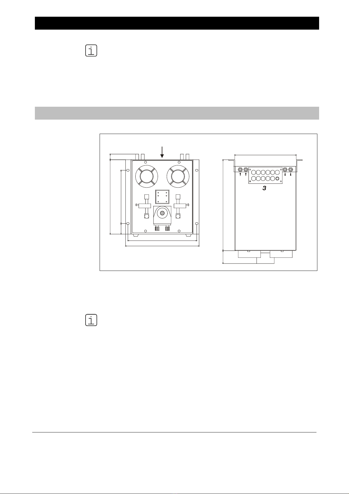
Details on the
rating plate
The details on the rating plate are applicable for the version of the sample gas feed
unit.

42/23-51 EN Rev. 3 SCC-F Sample gas feed unit Operator’s manual 5
General safety information
Requirements for
safe operation
In order to operate in a safe and efficient manner the unit should be properly
handled and stored, correctly installed and started, properly operated and carefully
maintained.
Personnel
qualifications
Only persons familiar with the installation, set-up, operation and maintenance of
comparable equipment and certified as being capable of such work should work on
the unit.
Important notes and
regulations
It is important to comply with:
The content of this operator’s manual
The safety information affixed to the unit
The applicable safety precautions for installing and operating electrical devices
Safety precautions for working with gases, acids, condensates, etc.
National regulations The regulations, standards and guidelines cited in this operator’s manual are
applicable in the Federal Republic of Germany. The applicable national regulations
should be followed when the unit is used in other countries.
Unit safety and safe
operation
The unit is designed and tested in accordance with EN 61010 Part 1, “Safety
provisions for electrical measuring, control, and laboratory instruments” and has
been shipped ready for safe operation.
To maintain this condition and to assure safe operation, read and follow the safety
information identified with the symbol in this manual. Failure to do so can put
persons at risk and can lead to unit damage as well as damage to other systems
and instruments.

6 SCC-F Sample gas feed unit Operator’s manual 42/23-51 EN Rev. 3
Safety tips for handling electronic measurement devices
Protective lead
connection
The protective lead should be attached to the protective lead connector before any
other connection is made.
Risks of loss of
protective lead
continuity
The unit can be hazardous if the protective lead is interrupted inside or outside the
unit or if the protective lead is disconnected.
Proper operating
voltage
The unit voltage must be set to match the line voltage before the power supply is
activated.
Risks involved in
opening the covers
Current-bearing components can be exposed when the covers or parts are
removed, even if this can be done without tools. Current can be present at some
connection points.
Risks involved in work-
ing with an open unit
The unit must be disconnected from all power sources before any maintenance
work is performed.
Charged capacitors The unit capacitors can retain their charge even when the unit is disconnected from
all power sources.
Use of proper fuses Only fuses of the specified type and rated current should be used as replacements.
Never use patched fuses. Do not short-circuit the fuse holder contacts.
When safe operation
can no longer be
assured
If it is apparent that safe operation is no longer possible, the unit should be taken
out of operation and secured against unauthorized use.
The possibility of safe operation is excluded:
If the unit is visibly damaged
If the unit is no longer operational
After prolonged storage under adverse conditions
After severe transport stresses.
WARNING
EXPLOSION HAZARD
Substitution of components may impair suitability for Class I, Division 2.
Do not disconnect equipment unless power has been switched off or the area is
known to be non-hazardous.
I/O connectors must only be connected to Class 2 circuits.

42/23-51 EN Rev. 3 SCC-F Sample gas feed unit Operator’s manual 7
Chapter 2 Preparing the installation
Requirements for the installation site
Installation location
requirements
The sample gas feed unit is only intended for installation indoors.
The max. altitude of the installation site may not exceed 2000 m above sea level.
The installation site must be stable enough to bear the weight of the sample gas
feed unit (max. 15 kg)!
Short gas paths The sample gas feed unit should be installed as close as possible to the gas
analyzer.
Adequate
air circulation
Ensure adequate natural air circulation around the sample gas feed unit. Avoid
heat accumulation.
Protection against
adverse environ-
mental conditions
The sample gas feed unit should be protected from
Cold,
Radiated heat, e.g. from the sun, kilns or boilers,
Temperature fluctuations,
Strong air movement,
Dust deposits and dust penetration,
Corrosive atmosphere,
Vibration.
Climatic conditions Ambient temperature In operation: +5 to +45 °C
Storage and transport: –25 to +60 °C
Relative humidity 75 % year-round average, 95 % on 30 days per year,
occasional light condensation permissible

8 SCC-F Sample gas feed unit Operator’s manual 42/23-51 EN Rev. 3
Power supply
Power supply Input voltage 230 V AC or 115 V AC, 50 Hz or 60 Hz
Power consumption max. 185 VA
Sample gas inlet conditions
Sample gas inlet
conditions
Sample gas pressure pabs = 70 to 105 kPa (0.7 to 1.05 bar)
Sample gas flow Gas paths 1 and 2 max. 100 l/h,
bypass max. 200 l/h
Sample gas inlet temperature +10 to +50°C
Sample gas inlet dew point The dew point of the sample gas must be at least
5 °C lower than the lowest ambient temperature
anywhere in the sample gas feed path. If this is not
the case, then a sample gas cooler unit or a
condensate trap is required.
Scope of delivery
Scope of delivery Quantity Description
1 SCC-F sample gas feed unit
2 Operator’s manuals (1 copy in German, 1 in English)
8 Fastening screws M5 x 12 (4 x recessed head, 4 x hexagon socket;
for installing side-by-side with the SCC-C sample gas cooler)
1 Rubber bushing with 18 mm inside diameter
(for the cables to/from the SCC-C sample gas cooler)
1 Power supply connection cable, 3-conductor, length approx. 50 cm
1 Connection cable, 2-conductor, length approx. 40 cm
The fixing brackets are fitted in the factory.

42/23-51 EN Rev. 3 SCC-F Sample gas feed unit Operator’s manual 9
Chapter 3 Installation and start-up
If there is shipping damage which points to improper handling, file a damage
claim with the shipper (railway, mail or freight carrier) within seven days.
Make sure that none of the enclosed accessories are lost during unpacking
(see section “Scope of delivery”, page 8).
Keep the shipping box and packaging material for future shipping needs.
Installing the sample gas feed unit
Figure 1
Dimensional drawing:
Sample gas feed unit
(Dimensions in mm)
1 Sample gas inlet
2 Sample gas outlet
3 Cable bushings
4 Flow monitor with needle valve
5 Dosing pump
6 Condensate monitor
7 LED display and reset switch for
condensate and flow alarm
You must take the additional space requirement into account
adjacent to the unit on the left-hand side for the cooling air inlet
(approx. 10 cm),
in front of and underneath the unit for running and connecting the reagent pipes
to the dosing pump (option) and
above the unit for running and connecting the sample gas lines and the
electrical leads.
The fixing brackets are fitted in the factory, with about 2.5 cm projection to the
rear wall. This projection must not be reduced.
Slope max. 5°.
The user is responsible for the secure mounting of the unit.
Figure 1 shows options. The scope and features of the ordered version may
differ.
Continued on next page
12
4
5
4
7
66
Z
A
nsicht
/
View Z
326.5
6
26
3.81.5
0
0
4
220
79
6
246
263
2

10 SCC-F Sample gas feed unit Operator’s manual 42/23-51 EN Rev. 3
Installing the sample gas feed unit, continued
Installation of the sample gas feed unit and the sample gas cooler side-by-side is
described on page 11.
Sample gas feed unit
installation on a
mounting plate
Step Action
1 Fit the unit to the mounting plate using 4 M6 screws (not supplied). The
fixing brackets required for this purpose are screwed securely on the
rear of the side panels in the factory.
To enable the cooling air to pass unobstructed out of the unit to
the rear, the projection of the fixing brackets of around 2.5 cm to
the rear wall, which is set up in the factory, must not be reduced.
Sample gas feed unit
installation in a 19-inch
cabinet /rack
Step Action
1 Unscrew the mounting brackets from the rear of the side covers and
screw them securely at the front of the side covers, flush with the front
cover, using the drill holes provided for this purpose.
2 Install the unit in a 19-inch cabinet/rack using 4 M6 screws.
Release the diaphragm
pumps transportation
restraints
Step Action
1 Use a Ph2 crosshead screwdriver to loosen the two M6x25 screws in
the base plate.
Retain the screws in case the unit needs to be transported again
in the future.

42/23-51 EN Rev. 3 SCC-F Sample gas feed unit Operator’s manual 11
Installing the sample gas feed unit and sample gas cooler
side-by-side
Installing the sample
gas feed unit and
sample gas cooler
side-by-side
The best way to install the SCC-F feed unit and the SCC-C cooler unit in a 19-inch
cabinet or a 19-inch rack is side-by-side. In this case, the sample gas feed unit
should be installed on the left and the cooler unit on the right (see Figure 2).
“Right”, “left” etc. should always be interpreted from a position facing
towards the unit’s front panel.
Figure 2
Dimensional drawing:
Sample gas feed unit
and sample gas
cooler side-by-side
(Dimensions in mm)
You must take the additional space requirement into account
adjacent to the units on the right-hand and left-hand side for the cooling air inlet
and in front of the units for the cooling air outlet (approx. 10 cm in each case),
in front of and underneath the units for running and connecting the condensate
and reagent pipes and
above the units for running and connecting the sample gas lines and the
electrical leads.
Slope max. 5°.
The user is responsible for the secure mounting of the units.
Continued on next page
266
301.537.8190.5
46
20
5,0
469
486
440
325
22.5

12 SCC-F Sample gas feed unit Operator’s manual 42/23-51 EN Rev. 3
Installing the sample gas feed unit and sample gas cooler
side-by-side, continued
Install the sample
gas feed unit and
sample gas cooler
side-by-side
(see Figure 2)
Step Action
Prepare sample gas feed unit for installation:
1 Unscrew the right-hand fixing bracket.
2 Undo the 4 fastening screws on the front panel and open it forwards
(the front panel remains attached in the rebate of the base plate).
3 Undo the 6 fastening screws on the casing cover, release the cable lug
of the protective lead from the quick terminal on the inside of the
casing cover, then remove the casing cover.
4 Undo the 6 fastening screws on the left-hand casing panel, release the
cable lug of the protective lead from the quick terminal on the inside of
the casing panel, then remove the casing panel.
5 Remove the dummy plug from the drill hole in the right-hand casing
panel.
Prepare sample gas cooler for installation:
6 Unscrew the left-hand fixing bracket.
7 Undo the 4 fastening screws on the front panel and open it forwards
(the front panel remains attached in the rebate of the base plate).
8 Undo the 8 fastening screws on the covering hood, release the cable
lug of the protective leads from the quick terminal on the inside of the
covering hood, then lift the covering hood off.
9 Remove the dummy plug from the drill hole in the left-hand casing
panel.
Screw sample gas feed unit and sample gas cooler together:
10 From inside the unit, insert one of the M5x12 screws (supplied with
sample gas feed unit) into the lower rear drill hole 1in the sample gas
feed unit’s right-hand side panel. Press on the screw with a screw-
driver, push the casings together, and screw the screw into the lower
rear threaded hole in the sample gas cooler’s left-hand side panel.
Sample gas feed unit
viewed from the left
1– Holes for
4screws M5x12
5 Hole for
cable bushing
11 Again from inside the unit, screw the remaining 3 M5x12 screws
through holes 2 – 4 in the sample gas feed unit’s right-hand side panel
into the corresponding threaded holes in the sample gas cooler’s left-
hand side panel. Make sure that the casings are aligned precisely
relative to one another, then tighten all 4 screws.
12 Insert the rubber bushing in the hole 5.
Continued on next page
1
2
3
4
5

42/23-51 EN Rev. 3 SCC-F Sample gas feed unit Operator’s manual 13
Installing the sample gas feed unit and sample gas cooler
side-by-side, continued
Install the sample
gas feed unit and
sample gas cooler
side-by-side
(continued)
Step Action
Connect electrical leads:
13 Connect the signal, control and power supply leads.
SCC-F without I/O card: see instructions on page 15,
SCC-F with I/O card: see instructions on page 18.
Close casings of sample gas feed unit and sample gas cooler:
14 Replace and secure the sample gas cooler’s covering hood as well as
the sample gas feed unit’s left-hand casing panel and casing cover; in
the course of this operation, the cable lugs of the protective leads
should be pushed back onto the quick terminals. Close and secure the
front panels.
Take care not to squash any cables or hoses.
Installing the sample gas feed unit/sample gas cooler combination:
15
Two people are required to transport and install the feed/cooler
unit combination.
Fitting in a 19-inch cabinet/rack:
Unscrew the fixing brackets from the rear of the side panels and screw
them securely at the front of the side panels using the drill holes
provided for this purpose. Fit the feed/ cooler unit combination to the
wall using 4 M6 screws (not supplied).
Fitting to a mounting plate:
Fit the feed/cooler unit combination using 4 M6 screws (not supplied).
The fixing brackets required for this purpose are screwed securely on
the rear of the side panels in the factory.
To enable the cooling air to pass unobstructed out of the sample
gas feed unit and sample gas cooler to the rear, the projection of
the fixing brackets of around 2.5 cm to the rear wall, which is set
up in the factory, must not be reduced.
Release the diaphragm pumps and compressor transportation restraints
16 Use a Ph2 crosshead screwdriver to loosen the two M6x25 screws in
the sample gas feed unit’s base plate.
Retain the screws in case the unit needs to be transported again
in the future.
17 Using a Ph2 crosshead screwdriver, turn the two screws counter-
clockwise through the sample gas cooler’s base plate up to the point at
which resistance can be felt.

14 SCC-F Sample gas feed unit Operator’s manual 42/23-51 EN Rev. 3
Connecting the electrical leads: Notes
CAUTION!
Follow all applicable national safety regulations for the installation and
operation of electrical devices as well as the following safety precautions.
The sample gas feed unit voltage must be set to match the line voltage
before the power supply is connected (see rating plate).
The protective lead should be attached to the protective lead connector
before any other connection is made.
The sample gas feed unit can be hazardous if the protective lead is inter-
rupted inside or outside the sample gas feed unit or if the protective lead is
disconnected.
You should route the signal lines separately from the power supply lines.
Control of the
diaphragm pumps
The internal control of the diaphragm pumps is dependent on the positions of
jumpers JP1 and JP2 (see below; see also Figure 4).
For maintenance purposes it is also possible to switch the pumps off using external
switches (see Figure 3)
Internal control of the
diaphragm pumps
Jumper Open (factory setting) Closed
JP1 Condensate alarm 1 switches off
diaphragm pump 1
Condensate alarm 1 does not
switch off diaphragm pump 1
JP2 Condensate alarm 2 switches off
diaphragm pump 2
Condensate alarm 2 does not
switch off diaphragm pump 2
Connection of the
sample gas cooler
to the sample gas
feed unit
If the SCC-F sample gas feed unit and the SCC-C sample gas cooler are used
together (e.g. in an analysis system), the electrical leads from the sample gas
cooler can be connected to the sample gas feed unit:
Temperature monitoring status signal (temperature alarm, in SCC-F without
I/O card),
Pt 100 resistance thermometer signal (temperature monitoring, in SCC-F with
I/O card),
Power supply.
In the event of a temperature alarm in the sample gas cooler the diaphragm pumps
in the sample gas feed unit are switched off.
Sample gas feed unit
with I/O card
The sample gas feed unit with integral I/O card is connected to the system bus of
the AO2000 Series gas analyzers. In this case it may be necessary (this depends
on the system bus layout) to interrupt the internal system bus connection between
the analyzer module and the electronics module in the gas analyzer. For detailed
information refer to the section “System bus connection” in the “AO2000 Series”
operator’s manual (Document No. 42/24-10 EN).

42/23-51 EN Rev. 3 SCC-F Sample gas feed unit Operator’s manual 15
Connecting the electrical leads: SCC-F without I/O card
Connecting the
electrical leads
(see Figures 3, 4 and 5)
Step Action
Connect signal and control leads to the sample gas feed unit:
1 Connect the status signal leads of the condensate and flow monitoring
to terminal strip X3.
2 If necessary connect the external control leads (230 VAC, max. 1 A) of
the diaphragm pumps and the dosing pump to terminal strip X4.
Before connecting the leads remove the factory-installed wire
jumpers from the respective terminals. Do not remove the wire
jumpers from the unused terminals.
If necessary connect the sample gas cooler to the sample gas feed unit:
3 Side-by-side installation: Pull the connection cables for temperature
alarm and power supply of the sample gas cooler (delivered with the
unit, see section “Scope of delivery”, page 8) through the rubber
bushing.
4 Connect the 2-wire connection cable for the temperature alarm
to terminals 4 and 8 on terminal strip X4 in the sample gas feed unit
and
to terminals 2 and 3 on terminal strip X3 in the sample gas cooler.
If the sample gas cooler is provided with a signal cable wires
2 (C) and 3 (NO) of this cable can be used for this purpose.
5 Connect the 3-wire connection cable for the sample gas cooler’s power
supply
to terminals 1, 2 and 3 on terminal strip X1 in the sample gas feed
unit and
to terminals 2, 3 and 4 on terminal strip X1 in the sample gas cooler.
If the sample gas cooler is provided with a power supply cable
this cable can be used to connect the sample gas feed unit to
the power supply (see step 9).
Connect the power supply to the sample gas feed unit::
6
Make sure the voltage setting shown on the rating plate matches
the line voltage.
7 Make sure the power supply leads have an adequately dimensioned
protective device (breaker).
8 Install a switched outlet or a breaker in the power supply wiring near
the sample gas feed unit. This should allow the sample gas feed unit to
be completely disconnected from the power supply if necessary. The
disconnection device should be identified in such a way that its
relationship to the equipment that it is designed to disconnect can be
clearly seen.
9 Connect the power supply leads to terminals 4, 5 and 6 on terminal
strip X1.
10 Connect the power supply leads to the power supply.
The sample gas feed unit may start when the power supply is
connected.
Continued on next page

16 SCC-F Sample gas feed unit Operator’s manual 42/23-51 EN Rev. 3
Connecting the electrical leads: SCC-F without I/O card, continued
Figure 3
Connection diagram:
Sample gas feed unit
without I/O card
Continued on next page
1
2
9
10
3
4
11
12
5
6
13
14
7
8
15
16
X3
X4
X1
3
6
2
5
1
4
SCC-F
1
5
2
6
3
7
4
8
L
N
PE
230/115 VAC
NC
NC
NC
NC
C
C
C
C
NO
NO
NO
NO
LA1
LA2
FA1
FA2
NC
NC
NC
NC
C
C
C
C
NO
NO
NO
NO
Power Supply
Input
Liquid Alarm 1
Liquid Alarm 2
Flow Alarm 1
Flow Alarm 2
External Control
Diaphragm Pump 1
External Control
Diaphragm Pump 2
External Control
Dosing Pump
X1
PE
N
L
3
2
X3
SCC-C
NO
C
230/115 VAC 4
3
2
Temperature Alarm
Power Supply

42/23-51 EN Rev. 3 SCC-F Sample gas feed unit Operator’s manual 17
Connecting the electrical leads: SCC-F without I/O card, continued
Figure 4
Terminal strip
positions in the
sample gas feed unit
without I/O card
X1 Power supply input and output (to SCC-C sample gas cooler)
X2 Power supply of the pumps (internal connections)
X3 Status signals of the condensate and flow monitoring
X4 External control of the diaphragm pumps and dosing pump;
temperature alarm
X6 Condensate sensors 1 and 2, flow sensors 1 and 2 (internal connections)
JP1 Internal control of diaphragm pump 1
JP2 Internal control of diaphragm pump 2
Figure 5
Terminal strip
positions in the
SCC-C sample gas
cooler
X1 Power supply
X2 Internal power supply voltage switching
X3 Status signal (temperature alarm)
X4 Pt 100 resistance thermometer (option)
X5 Power supply of the internal modules
X6 Temperature controller
SL
1 2 3
X1
X1
4 5 6
L N PE
L N PE
F1
2 A T
F2 50 mA T
10 9 8 7 6 5 4 3 2 1
230V 230V
115V 115V
JP2
X4
X1
LNPE
NC
C
NO

18 SCC-F Sample gas feed unit Operator’s manual 42/23-51 EN Rev. 3
Connecting the electrical leads: SCC-F with I/O card
Connecting the
electrical leads
(see Figures 5, 6 and 7)
Step Action
Connect signal and control leads to the sample gas feed unit:
1 Connect the status signal leads of the external devices (e.g. conden-
sate collecting bottle, reagent supply bottle) to terminal strips X10
(digital inputs DI1 – DI6) and X6 (digital inputs DI7 – DI8). Tightening
torque of the screws 0.22–0.25 Nm.
Before connecting the leads remove the factory-installed wire
jumpers from the respective terminals. Do not remove the wire
jumpers from the unused terminals.
2 Connect the alarm signal leads to terminal strip X16 (digital outputs
DO1 and DO2). Tightening torque of the screws 0.22–0.25 Nm.
3 Connect the leads of the external solenoid valves (e.g. for zero gas
injection)
to terminals 8 and 9 on terminal strip X7 (gas feed path 1) and /or
to terminals 5 and 6 on terminal strip X4 (gas feed path 2) and/or
to terminals 7 and 8 on terminal strip X4 (gas feed path 3).
Tightening torque of the screws 0.5–0.6 Nm.
Observe the polarity of the connections!
If necessary connect the sample gas cooler to the sample gas feed unit:
4 Side-by-side installation: Pull both connection cables for the Pt 100
resistance thermometer and power supply of the sample gas cooler
(delivered with the unit, see section “Scope of delivery”, page 8)
through the rubber bushing.
If the sample gas cooler is provided with a signal cable for the
temperature alarm this cable should be disconnected from
terminal strip X3 since it is not intended to be connected to the
I/O card.
5 Connect the 2-wire connection cable for the Pt 100 resistance thermo-
meter
to terminals 7 and 8 on terminal strip X16 in the sample gas feed unit
and
to terminals 1 and 2 on terminal strip X4 in the sample gas cooler.
Tightening torque of the screws 0.22–0.25 Nm.
The Pt 100 resistance thermometer is connected to terminals 3
and 4 on terminal strip X4 in the sample gas cooler.
6 Connect the 3-wire connection cable for the sample gas cooler’s power
supply
to terminals L, N and PE on terminal strip X3 in the sample gas feed
unit and
to terminals 2, 3 and 4 on terminal strip X1 in the sample gas cooler.
Tightening torque of the screws 0.5–0.6 Nm.
If the sample gas cooler is provided with a power supply cable
this cable can be used to connect the sample gas feed unit to
the power supply (see step 12).
Connect the sample gas feed unit to the system bus:
7 Attach a T-piece to the system bus connector on the top of the
sample gas feed unit casing.
Connect the system bus cable to the T-piece.
Connect a termination resistor to the free end of the T-piece.
Continued on next page

42/23-51 EN Rev. 3 SCC-F Sample gas feed unit Operator’s manual 19
Connecting the electrical leads: SCC-F with I/O card, continued
Connecting the
electrical leads
(continued)
Step Action
Connect the power supply to the sample gas feed unit:
8 Make sure the voltage setting shown on the rating plate matches
the line voltage.
9 Observe the requirements for the power supply cables!
Sample gas feed unit: Outer diameter 4.5–10 mm, suitable for cable
gland M16; wire cross-section 3 x min. 1.5 mm2; flammability class
VW-1 and FT-1; temperature resistance ambient temperature > 60 °C.
External solenoid valves: Outer diameter 3–7 mm, suitable for cable
gland M12; wire cross-section 2 x min. 1.5 mm2; flammability class
VW-1 and FT-1; temperature resistance ambient temperature > 60 °C.
10 Make sure the power supply leads have an adequately dimensioned
protective device (breaker max. 20 A).
11 Install a switched outlet or a breaker in the power supply wiring near
the sample gas feed unit. This should allow the sample gas feed unit to
be completely disconnected from the power supply if necessary. The
disconnection device should be identified in such a way that its
relationship to the equipment that it is designed to disconnect can be
clearly seen.
12 Connect the power supply leads to terminals L, N and PE on terminal
strip X1. Tightening torque of the screws 0.5–0.6 Nm.
13 Connect the power supply cable to the power supply.
The sample gas feed unit may start when the power supply is
connected.
Continued on next page

20 SCC-F Sample gas feed unit Operator’s manual 42/23-51 EN Rev. 3
Connecting the electrical leads: SCC-F with I/O card, continued
Figure 6
Connection diagram:
Sample gas feed unit
with I/O card
Continued on next page
1
2
3
4
5
6
7
8
-
+
-
+
-
+
-
-
-
+
+
+
9
10
11
12
1
2
3
4
5
6
7
8
8
5
7
9
6
8
X16
X6
X10
X7
X4
X3
X1
PE
PE
N
N
L
L
SCC-F
-
-
+
+
1
2
3
4
-
-
+
+
DI7
DI8
230/115 VAC
DO1 NC
C
NO
DO2 NC
C
NO
DI1
DI2
DI3
DI4
DI5
DI6
-
-
-
-
-
-
+
+
+
+
+
+
max. 30 V / 1 A
(General Purpose)
max. 30 V / 1 A
(General Purpose)
N
N
N
230/115 VAC
1)
230/115 VAC
1)
230/115 VAC
1)
L
L
L
1) B300 Pilot Duty (360VA max @ 240 VAC)
12
12
to 24 V DC
to 24 V DC
Power supply
input
Solenoid valve gas path 1
Solenoid valve gas path 2
Solenoid valve gas path 3
12
12
12
12
12
12
to 24 V DC
to 24 V DC
to 24 V DC
to 24 V DC
to 24 V DC
to 24 V DC
Reagent bottle 1
Level too low
Reagent bottle 2
Level too low
Condensate bottle 2
Level too high
Condensate bottle 1
Level too high
Standard assignment:
PE
N
L
1
3
2
4
X4
Pt 100
SCC-C
X1
4
3
2
T
230/115 VAC
Power supply
Table of contents
Other ABB Industrial Equipment manuals
Popular Industrial Equipment manuals by other brands

Victron energy
Victron energy Phoenix Multi Series installation manual

Rauch
Rauch AERO ISOBUS Complementary instructions

Siemens
Siemens HMS-S installation instructions

SKF
SKF TMHP 15/260 Instructions for use

Schaeffler
Schaeffler ProLink instruction manual

Bosch
Bosch Rexroth ActiveMover Assembly instructions

CommScope
CommScope HELIAX FiderFeed DFJ-4S112B Technical publication

Parkside
Parkside MAGNETIC TORCH STAND PBHM 16 A1 Operation and safety notes

CAB
CAB 3014 Assembly instructions

Trane
Trane AFDH installation instructions

Lumen Dynamics Group
Lumen Dynamics Group OmniCure LX400+ user guide

KTC
KTC GOD80E instruction manual