stellar labs TMAX1 User manual

! )+,& ')"%$,"$) $$ ,$()##)"%$,')(
-
Stellar Industries, Inc.
190 State Street
P Box 169
Garner, IA 50438
800-321-3741
Fax: 641-923-2811
www.stellarindustries.com Last Revision: 11/15/10
Subject to Change without otification.
© 2010 Stellar Industries, Inc.

TMAX1 Manual Revisions
Date of Revision Description of RevisionSection Revised

Table of Contents "
Table of Contents
Int oduction...................................................................................ii
TMAX Service Body Terminology and Specifications..........iii
Chapter 1 - peration................................................................1
Masterlock Operation.............................................................1
Air Drain Operation .................................................................1
Stabilizer Operation.................................................................1
Tailgate Operation ..................................................................1
VEC (Vehicle Electrical Center) Operation..........................2
Door Latch Operation.............................................................2
Sliding Top Operation..............................................................2
Crane Drain Pan Operation...................................................2
Chapter 2 - Maintenance ..........................................................3
A note about washing the TMAX body:...............................4
Torque Data Chart ..................................................................4
Mounting Kit - Ford Chassis - P 13258 .................................5
Chapter 3 - Installation...............................................................5
Mounting Kit - Dodge Chassis - P 57645............................6
Wiring Harness: CS Compartment Lights - P 15915 ...........7
Wiring Harness: SS Compartment Lights - P 14427 ............7
Wiring Harness: Rear Body - P 15690...................................8
Wiring Harness: VEC System - P 34109 ................................9
Wiring Harness: VEC System Connector Breakdown ........10
Wiring Harness: Jumper VEC System - P 37051................11
Welder Installation .................................................................12
Electrical Circuit Grounding .................................................12
Chapter 4 - Assembly Drawings..............................................13
Tailgate Assembly - P 21401...............................................13
Light Box/Reflector Assembly...............................................14
Grab Handle Assembly.........................................................15
Mud Flap Assembly - P 19494............................................16
Harness Guard Kit Assembly - P 54549 .............................17
Ford Fuel Fill Assembly - P 54715........................................18
License Plate Hardware Assembly - P 54548 ...................19
Chapter 5 - Replacement Parts...............................................21
Wa anty Info mation ................................................................22

"" TMAX1 Owne ’s Manual
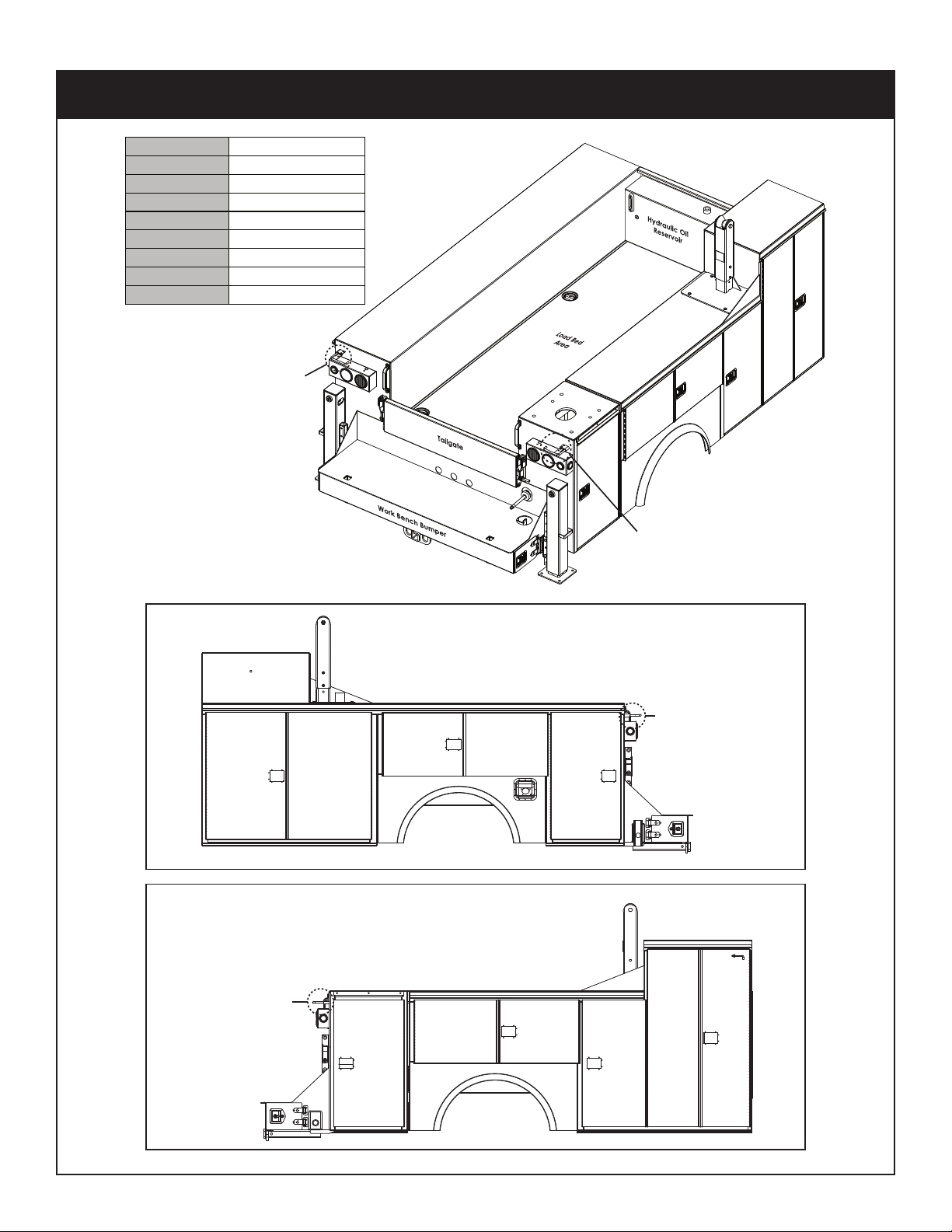
Stellar® Service Bodies are designed to
provide safe and dependable service for a
variety of operations. With proper use and
maintenance, these bodies will operate at
peak performance for many years.
To promote this longevity, carefully study
the information contained in this manual
before putting the equipment into service.
Though it is not intended to be a training
manual for beginners, this manual should
provide solid guidelines for the safe and
proper usage of the service body.
Once you feel comfortable with the
material contained in this manual, strive to
exercise your knowledge as you safely
operate and maintain the service body.
This process is vital to the proper use of the
unit.
A few notes on this manual:
A copy of this manual is provided with
every service body and can be found in
the hard plastic manual case that is
installed on the chassis. This manual shall
remain with the service body at all times.
Information contained within this manual
does not cover all maintenance, operating,
or repair instructions pertinent to all possible
situations.
Please be aware that some sections of this
manual contain information pertaining to
Stellar manufactured service bodies in
general and may or may not apply to your
specific model.
This manual is not binding. Stellar Industries,
Inc. reserves the right to change, at any
time, any or all of the items, components,
and parts deemed necessary for product
improvement or commercial/production
purposes. This right is kept with no
requirement or obligation for immediate
mandatory updating of this manual.
In closing:
If more information is required or technical
assistance is needed, or if you feel that any
part of this manual is unclear or incorrect,
please contact the Stellar Customer Service
Department by phone at 800-321-3741 or
email at [email protected].
Introduction
ATTENTI N
Failure to adhere to the instructions
could result in property damage or
even serious bodily injury to the
operator or others close to the
service body.
For Technical Questions, Information, Parts, or Warranty, Call Toll-Free at
800-321-3741
Hours: Monday - Friday, 8:00 a.m. - 5:00 p.m. CST
Or email at the following addresses:
Technical Questions, and Information [email protected]
Warranty Information [email protected]

Curbside
Stabilizer
Streetside
Stabilizer
Curbside
Crane
Compartment
Work Bench
Bumper
Work Bench
Bumper
Streetside Compartment
Master Locking Arm
Curbside Compartment
Master Locking Arm
Curbside Compartment
Master Locking Arm
Streetside Compartment
Master Locking Arm
Curbside
2nd Vertical
Compartment
(CS2V)
Streetside
3rd Vertical
Compartment
(SS3V)
Streetside
2nd Vertical
Compartment
(SS2V)
Streetside
1st Vertical
Compartment
(SS1V)
Curbside
1st Vertical
Compartment
(CS1V)
Curbside Horizontal
Compartment
Streetside Horizontal
Compartment
Crane Boom
Support
Crane Boom
Support
Streetside View
Curbside View
Applicable Chassis 16,000 to 19,000 GVWR
Cab to Axle 84” (213.36 cm)
Body Length Nominal 133” (337.82 cm)
Body Height 44” (111.76 cm)
Body Width 94” (238.76 cm)
Compartment Depth 22” (55.88 cm)
Floor Width 50” (127 cm)
Net Weight 3220 lbs (1460.37 kg)
Crane Models 3315, 4420, 5520, 7621, 7628
"""
TMAX Service Body Terminology and Specifications

"* TMAX1 Owne ’s Manual

Tailgate peration
Lowering the tailgate
Step 1: Pull upward on the red post/bar attached to the right side linkage of the tailgate.
Step 2: ow pull downward on the tailgate.
Closing/Stowing the tailgate
Step 1: Pull upward on the red post/bar attached to the right side linkage.
Step 2: Push the tailgate upward until it stops.
Step 3: Pull downward on the red post/bar to lock the tailgate in place.
Ope ation
This chapter contains information regarding the operation of Stellar manufactured service
bodies. Please study the following pages to ensure your familiarity with the operation
process. This understanding is vital to the safe and efficient operation of the service body.
Stabilizer peration
Before operating the stabilizers, make sure that the service truck is parked on an even sur-
face and be aware of the surface the truck has been positioned upon. The area should
be a firm supporting surface.
Note: Stand clear when deploying stabilizers.
Step 1: Fully extend the stabilizer beam. ote: Manual beams will have to be pulled out.
If equipped with a power out option, push downward on the far left valve bank
lever until the beam stops moving outward.
Step 2: Lower the curbside stabilizer leg by pushing down on the center valve bank lever.
Lower the stabilizer until it makes good contact with the firm supporting surface. If
equipped with manual crankdown legs, manually lower the legs until they make
good contact with the supporting surface. Avoid over-extending the stabilizers
legs. The truck tires should remain in contact with the ground surface.
Step 3: Lower the streetside stabilizer leg by pushing downward on the right valve bank
control lever. Lower the stabilizer until it makes good contact with the firm support-
ing surface. If equipped with manual crankdown legs, manually lower the legs
until they make good contact with the supporting surface. Avoid over-extending
the stabilizers legs. The truck tires should remain in contact with the ground sur-
face.
Air Drain peration
Depending on where and how the air drain valve is mounted to the body determines the
operation. Follow the decal instructions for correct positioning of the valve handle.
Note: Always drain air tank/receiver before leaving a job or work site. Air tank should not
have compressed air while driving the service truck.
Masterlock peration
Step 1: Close all doors.
Step 2: Push and hold locking bar in the detent position.
Step 3: While holding locking bar in detent position, insert locking device in aligned holes.
ote: Perform these steps for each applicable side pack.
Chapter 1 - peration

TMAX1 Owne ’s Manual
Crane Drain Pan peration
Removing the Drain Pan
Step 1: Pull the quick release pin located on the right side of the drain pan.
Step 2: Slide the drain pan to the right (Toward the right side wall of the crane compart-
ment).
Step 3: Lower the drain pan and clean as needed. Remove debris and clean the drain
tube.
Re-Installing the Drain Pan
Step 1: Lift the drain pan, staying toward the right side of the crane compartment.
Step 2: Re-align the tab brackets to the drain pan slots.
Step 3: Slide the drain pan pin to the left (Toward the rear of the body).
Step 4: Re-install the quick release pin.
Sliding Top peration
pening the Sliding Top
Step 1: Pull the latch assembly T-Handle outward.
Step 2: Turn the T-Handle counter-clockwise to unlatch the door rods from the rod guides.
Step 3: Pull the door assembly upward and over until the door holders snap into the holder
sockets.
Step 4: Using both hands, apply even pressure and push the rear sliding top assembly for-
ward until it stops.
Closing the Sliding Top
Step 1: Using both hands, pull the rear sliding top section toward the rear of the body until
it stops.
Step 2: With the tailgate assembly in the stowed and locked position, pull up and then
downward on the door assembly.
Step 3: Turn the T-Handle clockwise until the door rods slide into the rod guides.
Step 4: Push the T-Handle back into the latch assembly pocket.
Door Latch peration
Step 1: To open, pull the T-Handle portion of the latch outward.
Step 2: Turn T-Handle as follows:
Curbside Door Latches: Turn handle clockwise to open the door.
Streetside Door Latches: Turn handle counter-clockwise to open the door.
VEC (Vehicle Electrical Center) peration
Starting the VEC
Step 1: Engage the chassis parking brake.
Step 2: Press the main power switch on the VEC Control Panel.
Step 3: Press option switches as needed.
Shutting off the VEC
Step 1: Push any of the engaged option switches to disengage.
Step 2: Push the main power switch to shut off the VEC Control Panel.

Maintenance
Chapter 2 - Maintenance
Maintenace Item Action Note Interval
Door Latch
Assembly
Inspect and
Lubricate
Lubricate with EP2 grease or light-weight
lithium spray grease.
Monthly
Door Rod Guides
Inspect and
Lubricate
Lubricate with EP2 grease or light-weight
lithium spray grease.
Monthly
Door Spring Rod
Inspect and
Lubricate
Lubricate with EP2 grease or light-weight
lithium spray grease.
Monthly
Masterlock Rod
Guides
Inspect and
Lubricate
Lubricate with EP2 grease or light-weight
lithium spray grease.
Monthly
Door Hinge
Inspect and
Lubricate
Lubricate with EP2 grease or light-weight
lithium spray grease.
Quarterly
Tailgate
Inspect and
Lubricate
Lubricate hinges with light-lithium grease
or aerosol spray.
Quarterly
Body Mounting
Hardware
Inspect and
Torque
Inspect the mounting brackets for
damage or cracks. Check all mounting
cap screws for proper torque.
Quarterly
Compartment
Drain Plugs
Inspect and
Replace
Check the security of the compartment
drain plugs. Replace if they are
cracked or loose.
Monthly
Body Washing
Wash the
Body
Wash the body to prevent damage from
any type of corrosive substances
collected from roads or job sites.
Weekly
Weatherstripping
Inspect and
Replace
Check door and compartment
weatherstrip seal for rips or tears.
Replace as needed.
Quarterly
Decals
Inspect and
Replace
Inspect all decals attached to the body
to ensure that they are all still legible.
Replace as needed.
Monthly
Body Mounted
Lights
Inspect and
Replace
Inspect all body lights for damage and
replace as needed: Marker Lights,
Clearance Lights, Turn/Stop/Tail Lights,
Back-up Lights, Compartment Lights,
Flood Lights.
Daily

TMAX1 Owne ’s Manual
When using the to que data in the cha t,
the following ules should be obse ved:
1. Bolt manufacturer’s particular
specifications should be consulted when
provided.
2. Flat washers of equal strength must be
used.
3. All torque measurements are given in
foot-pounds. To convert to inch-pounds,
multiply by 12.
4. Torque values specified are for bolts with
residual oils or no special lubricants
applied. If special lubricants of high stress
ability, such as ever-Seez compound
graphite and oil, molybdenum disulphite,
colloidal copper or white lead are
applied, multiply the torque values in the
charts by the factor .90. The use of Loctite
does not affect the torque values listed
above.
5. Torque values for socket-head capscrews
are the same as for Grade 8 capscrews.
Size Bolt DIA Plain Plated Plain Plated Plated
(DIA-TPI) (Inches) (Ft-Lb) (Ft-Lb) (Ft-Lb) (Ft-Lb) (Ft-Lb)
5/16-18 0.3125 17 13 25 18 22
3/8-16 0.3750 31 23 44 33 39
7/16-14 0.4375 49 37 70 52 63
1/2-13 0.5000 75 57 105 80 96
9/16-12 0.5625 110 82 155115 139
5/8-110.6250 150 115 220 160 192
3/4-10 0.7500 265 200375280340
7/8-9 0.8750 395 295 605 455549
1-8 1.000590445910680823
1 1/8-7 1.1250 795 595 1290 965 1167
1 1/4-7 1.2500 1120 840 1815 1360 1646
1 3/8-6 1.3750 1470 1100 2380 1780 2158
1 1/2-6 1.500 1950 1460 3160 2370 2865
GRADE 5 GRADE 8 GRADE 9
Torque Data Chart
A note about washing the TMAX body:
The body should be washed at least once per week to prevent damage to the paint,
wiring or rubber material from any type of corrosive substances collected from roads or job
sites. When washing the body, avoid direct water spray toward electrical components
such as floodlights, radio remote receivers, the VEC center, and areas of the body which
may have rock chips.

Installation
Chapter 3 - Installation
Mounting Kit - Ford Chassis - PN 13258
EXISTING HOLES IN FORD CHASSIS.
DRILL EXISTING HOLES TO FIT 5/8 BOLT
1
OF SUBFRAME.
FORD MOUNTING HOLES.
FROM CAB TO FRONT
OF MOUNTING PLATE.
BODY MOUNT ON REAR
BODY MOUNT ON FRONT OF SUBFRAME
2
13.00
30.00
PN 13258
ITEM PART DESCRIPTION
1 13251PC BRKT BODY MOUNT FRONT RF
2 13254PC BRKT BODY MOUNT FRONT LF
3 C1025 CAP SCR 0.63-11X2.00 HHGR8 ZY
4 C1038 WASHER 0.63 FLAT
524868 NUT 0.63-11 HHGR8 NYLOCK ZY
6 13113 SUBRAME WLDMT 6620 CRANE BODY

40.94
ITEM PART DESCRIPTION
1 13253 SPACER REAR .38X3.00X25.00 GM
213251PCBRKT BODY MOUNT FRONT RF
3 13254PC BRKT BODY MOUNT FRONT LF
4 C1025 CAP SCR 0.63-11X2.00 HHGR8 ZY
5 C1038 WASHER 0.63 FLAT
62826NUT 0.63-11 HH NYLOC
724176SPACERT1 / 5500
8 57646SPACER FRONT D5500 2010
2
3
1
3
4
5
6
5
7
7
ARE SHOWN FOR REFERENCE ONLY.
NOTE: FRAME AND SUBFRAME WELDMENT
NOTE: AFTER LOCATING THE PART, IT CAN BE TACK
WELDED IN PLACE FOR EASE OF INSTALLATION
8
BODY SUBFRAME
MEASUREMENT FROM CENTER OF
AXLE TO REAR OF FRONT MOUNT
PN 57645
TMAX1 Owne ’s Manual
Mounting Kit - Dodge Chassis - PN 57645

Installation
Wiring Harness: SS Compartment Lights - PN 14427
PN 14427
Ground
Light
Connects to Rear
Body Harness (Streetside)
Routed Through Compartments
Wiring Harness: CS Compartment Lights - PN 15915
PN 15915 Ground
Light
Connects to Rear
Body Harness (Curbside)
Routed Through Compartments

TMAX1 Owne ’s Manual
Wiring Harness: Rear Body - PN 15690
PN 15690
Chassis
Turn Signal,
Back Up,
Tail Light
Connections
Connects to
Main Body
Harness
Note:
Label Trailer
Plug Wires

Installation
Wiring Harness: VEC System - PN 34109
PN 34109
Grey-Connector 2*
Red-Connector 2*
Green-Connector 11*
*Seen Next Page for Connector Breakdown
Brown-Connector 12*
Grey-Connector 1*

TMAX1 Owne ’s Manual
Wiring Harness: VEC System Connector Breakdown
DUAL VEC SINGLE VEC
FRONT VIEW
REAR
FRONT
PN 34109

Installation
Wiring Harness: Jumper VEC System - PN 37051
PN 37051
FRONT VIEW
REAR
FRONT
Connection to
Secondary VEC Box
Connection to
Primary VEC Box
Connection to
Crane Harness
Green - Connector 4
Green - Connector 4
Yellow - Connector 10

TMAX1 Owne ’s Manual
Welder Installation
When installing welders on Stellar® Mechanic body packages it is highly recommended
that you install an electrical surge protector to the chassis battery. If the electrical surge
protector is not installed on to the battery, your customer could experience failures to the
Chassis wiring circuit and also to the Stellar Mechanic body package wiring circuits. This
electrical surge protector will help protect the Chassis ECM (Electronic Control Module),
Transmission TCM (Transmission Control Module) and the Crane Radio Remote system
against any electrical surges or spikes caused by poor grounding or from operators using
the rear work bench bumper as a welding area.
Electrical Circuit Grounding
When installing product which requires 12 volt power to operate the equipment, always
locate a good source for grounding the circuit. A majority of electrical failures are due to
poor grounding. Poor grounding can cause intermittent operation of the equipment, elec-
trical component failures and cause the equipment to not operate at all. Chassis manu-
facturers usually will have a ground strap which ties into the truck frame from the battery,
but it is always a good idea to check each individual model to verify where the ground is
located. If you are installing a body onto the chassis, never use the body as a ground
source. If you add a crane or compressor to the body make sure the electrical grounds
are routed to either the chassis frame or the chassis’s main grounding source.

Assembly D awings
Chapter 4 - Assembly Drawings
Tailgate Assembly - PN 21401
6
7
16
7
13 12
7
14
16
12
11
8
10
2
9
5
5
16
4
3
13 11
16
16
516
8
10
16
17
8
1
ITEM PART DESCRIPTION QTY.
1 15848PC BRKT TAILGATE LH 15848 POWDERCOAT 1
2 21322PC TAILGATE WLDMT MCH 21322 POWDERCOAT 1
3 15849PC BRKT TAILGATE STOP 15849 POWDERCOAT 1
4 15846PC BRKT TAILGATE 15846 POWDERCOAT 3
5C4516WASHER 0.56IDX1.50ODX0.13 THK NYLON 8
1DRHT57.1X00.4X31-05.DUTS961226
7 22170 CAP SCR 0.50-13X1.50 HHGR5 SS 7
8SSCOLYN5RGHH31-05.0TUN461228
1SSCOLYNMAJHH31-05.0TUN561229
10 D1482 BOLT CARRIAGE 0.38-16X1.25 SS 4
4TALF83.0REHSAW643011
4COLYNHH61-83.0TUN743021
13 15851 PLUG PLASTIC 1.50 HOLE 85985K29 4
14 C5587 CAP PLASTIC 0.375IDX0.50ODX2.00LONG1
15 16094 DECAL STELLAR LOGO6.00X14.25REFLECT1
61SSTALFSSU05.0REHSAW8612261
17 15847PCBRKTTAILGATE RH 15847 POWDERCOAT1
PN 21401

TMAX1 Owne ’s Manual
Light Box/Reflector Assembly
7
36
5
7
4
1
13
10
11
13
10
812
11
ITEMPART DESCRIPTIONQTY.
1 20101 LIGHT BOX LH MECH1
2 20100 LIGHT BOX RH MECH1
3 22200 PLUG PLASTIC 1.00 HOLE BPF-12
4 17352 PLUG PLASTIC .375 HOLE BPF-3/82
5 0480 CAP SCR 0.25-20X1.00 HHGR512
6 0333 NUT 0.25-20 HHGR5 NYLOC 12
7 10334 GROMMET 4.00 ROUND LAMP (PETERSON) 4
8 13143 LIGHT STOP/TURN/TAIL 4 RND LED2
9 13144 LIGHT CLEARANCE AMBER RND 2 LED2
10 13145 LIGHT CLEARANCE RED RND 2 LED7
11 2320 LICENSE PLATE LIGHT ROUND 430 W2
12 27626 LIGHT BACKUP LED 623912
13 C4862GROMMET FOR 2 CLEARANCE 307009
14 0540 REFLECTOR 3.00 AMBER2
15 0541 REFLECTOR 3.00 RED4
2
15
15
14
13
9
13
10
Items 7-15
Included in
Light Kit
Mech Body
(PN 18746)
Table of contents
Other stellar labs Industrial Equipment manuals
Popular Industrial Equipment manuals by other brands

Siemens
Siemens Simatic S7-1500/ET 200MP System manual

STOKVIS ENERGY SYSTEMS
STOKVIS ENERGY SYSTEMS ECONOPLATE E3 Series Installation, operation & maintenance documentation

Nakanishi
Nakanishi AL-C1204 Operation manual

TradeQuip
TradeQuip 1019T owner's manual

ABB
ABB HT579538 Operation manual

Yale
Yale MWW Series operating instructions