CONTENTS
PRECAUTIONS
0.0...
eee
hehe
rue
hara
eer
rare
2
FRONT
PANEL
CONTROLS
......
0...
0
0c
c
cence
eet
n
eee
a
rera
haee
3
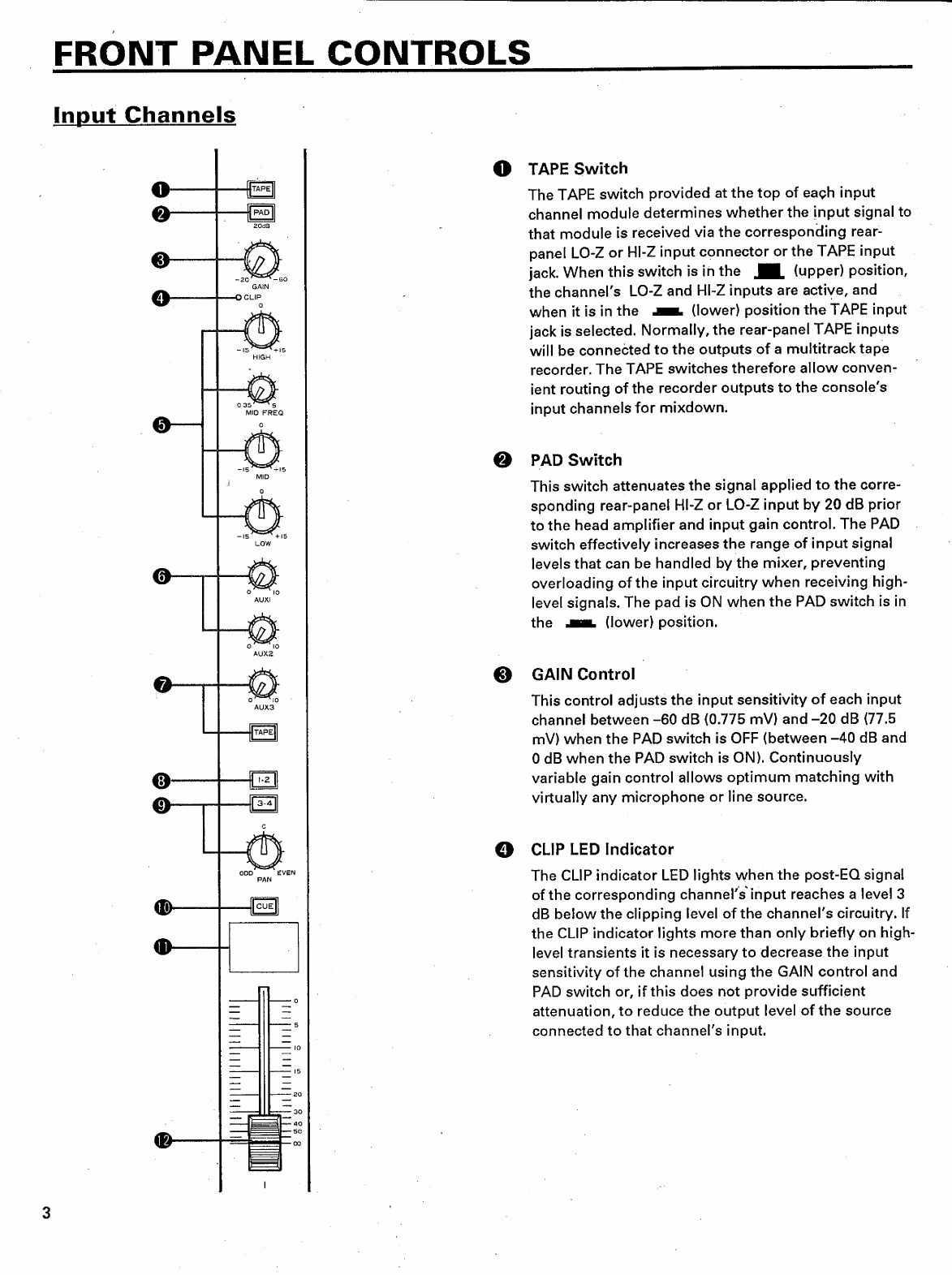
Input
Channels
....,.,,.........,...,,,,..,,,,.,,..,,,4,
TE
3
Master
Control
Section
0.0...
ccc
ce
ect
tee
ehh
haare
7
REAR
PANEL
CONNECTORS
AND
CONTROLS
..........
0...
ccc
cu
cece
cece
hh
hr]
naeh
9
SIGNAL
PATH
444444
ss
ss
here
ra
ha]
ah
ea
11
Main
Signal
Path
........
ccc
cc
cee
eee
cence
eevee
rh
haha
eaa
11
AUX
SEND
Signal
Path.......
eet
eee
ern
eet
eee
eennne
bees
11
AUX
RTN
Signal
Path
1.0...
0.
ccc
ccc
ccc
cece
m
tee
rennen
een
12
CUE
and
MONITOR
Signal
Path
......
0...
ccc
eee
e
eee
ete
rn
nennen
12
OPERATING
TIPS
,..................
PM
13
Connecting
Sources
..,,,,,,..4,,444444
4444
serres
sus
a
aes
HEP?
13
Connecting
Other
Equipment
..,..,..,,,,,,,,,,,,,4,,.4
44444
rar
ahh
hne
ha
13
Matching
Input
Levels
oo...
cc
cee
cece
teeter
Hh
hh
ra
ras
14
Equalization
.....
ccc
cece
eee
eee
ee
RR
RI
IR]
hrs]
14
SAMPLE
APPLICATIONS
,,...............4444
4,4
seems
ars
15
A
Recording
System
......,........,,,,,,,,,,,,,4,,4444
rema
aaa
ees
15
A
Sound
Reinforcement
System
...
12
cc.
cee
eee
ha]
mar
erras
16
SPECIFICATIONS
............,,,,,,.,,,,,,,444
44
hh
ah
aae
ehh
17
INPUT
and
OUTPUT
characteristics
ernennen
een
rea]
hh
hahere
hann
18
BIOCK
&
LEVEL
DIAGRAM
.......
0.0...
c
ccc
ccc
cence
ee
eee
eee
maa
aar
ae
ehe
58
PRECAUTIONS
1.
AVOID
EXCESSIVE
HEAT,
HUMIDITY,
DUST
AND
5.
HANDLE
CABLES
CAREFULLY
VIBRATION
Always
plug
and
unplug
cables
—
including
the
AC
cord
Keep
the
unit
away
from
locations
where
it
is
likely
to
be
—
by
gripping
the
connector,
not
the
cord.
exposed
to
high
temperatures
or
humidity
—
such
as
near
radiators,
stoves,
etc.
Also
avoid
locations
which
6.
CLEAN
WITH
A
SOFT
DRY
CLOTH
are
subject
to
excessive
dust
accumulation
or
vibration
.
.
Never
use
solvents
such
as
benzine
or
thinner
to
clean
which
could
cause
mechanical
damage.
the
unit.
Wipe
clean
with
a
soft,
dry
cloth.
2.
AVOID
PHYSICAL
SHOCKS
Strong
physical
shocks
to
the
unit
can
cause
damage.
Handle
it
with
care.
7.
ALWAYS
USE
THE
CORRECT
POWER
SUPPLY
Make
sure
that
the
power
supply
voltage
specified
on
the
rear
panel
matches
your
local
AC
mains
supply.
3.
DO
NOT
OPEN
THE
CASE
OR
ATTEMPT-REPAIRS
OR
MODIFICATIONS
YOURSELF
This
product
contains
no
user-serviceable
parts.
Refer
all
maintenance
to
qualified
YAMAHA
service
personnel.
Opening
the
case
and/or
tampering
with
the
internal
circuitry
will
void
the
warranty.
4.
MAKE
SURE
POWER
IS
OFF
BEFORE
MAKING
OR
REMOVING
CONNECTIONS
~
Always
turn
the
power
OFF
prior
to
connecting
or
dis-
`
connecting
cables.
This
is
important
to
prevent
damage
to
the
unit
itself
as
well
as
other
connected
equipment.