Yamaha MG24/14fx User manual

MG24/14FX
MG32/14FX
1
SERVICE MANUAL
PA 011696
MG24/14FX: 200309-138000
MG32/14FX: 200309-188000 Copyright (c) Yamaha Corporation. All rights reserved. PDF-K7781 ’03.09
HAMAMATSU, JAPAN
CONTENTS
SPECIFICATIONS ................................................ 3/5
DIMENSIONS ............................................................ 7
PANEL LAYOUT ..................................... 8
CIRCUIT BOARD LAYOUT ................ 17
WIRING .................................................................. 18
DISASSEMBLY PROCEDURE ........ 23
DISASSEMBLY PROCEDURE ........ 35
LSI PIN DESCRIPTION ............................... 47
IC BLOCK DIAGRAM .................................. 50
CIRCUIT BOARDS ....................................... 51
INSPECTIONS ....................................................... 65/72
PARTS LIST
BLOCK DIAGRAM & LEVEL DIAGRAM
OVERALL CIRCUIT DIAGRAM
(目次)
MIXING CONSOLE
MG32/14FX MG24/14FX
(
総合仕様
)
(
寸法図
)
(パネルレイアウト)
(ユニットレイアウト)
(結線図) (MG24/14FX分解手順)
(MG32/14FX分解手順)
(LSI端子機能表)
(ICブロック図)
(シート基板図)
(検査)
(ブロックダイアグラム&レベルダイアグラム)
(総回路図)

MG24/14FX
MG32/14FX
2
IMPORTANT NOTICE
This manual has been provided for the use of authorized Yamaha Retailers and their service personnel. It has been assumed
that basic service procedures inherent to the industry, and more specifically Yamaha Products, are already known and under-
stood by the users, and have therefore not been restated.
WARNING : Failure to follow appropriate service and safety procedures when servicing this product may result in per-
sonal injury, destruction of expensive components and failure of the product to perform as specified. For
these reasons, we advise all Yamaha product owners that all service required should be performed by an
authorized Yamaha Retailer or the appointed service representative.
IMPORTANT : This presentation or sale of this manual to any individual or firm does not constitute authorization certifi-
cation, recognition of any applicable technical capabilities, or establish a principal-agent relationship of
any form.
The data provided is belived to be accurate and applicable to the unit(s) indicated on the cover. The research engineering, and
service departments of Yamaha are continually striving to improve Yamaha products. Modifications are, therefore, inevitable
and changes in specification are subject to change without notice or obligation to retrofit. Should any discrepancy appear to
exist, please contact the distributor’s Service Division.
WARNING : Static discharges can destroy expensive components. Discharge any static electricity your body may have
accumulated by grounding yourself to the ground bus in the unit (heavy gauge black wires connect to
this bus.)
IMPORTANT : Turn the unit OFF during disassembly and parts replacement. Recheck all work before you apply power
to the unit.
WARNING: CHEMICAL CONTENT NOTICE!
The solder used in the production of this product contains LEAD. In addition, other electrical/electronic and/or plastic (Where
applicable) components may also contain traces of chemicals found by the California Health and Welfare Agency (and possibly
other entities) to cause cancer and/or birth defects or other reproductive harm.
DO NOT PLACE SOLDER, ELECTRICAL/ELECTRONIC OR PLASTIC COMPONENTS IN YOUR MOUTH FOR ANY REASON WHAT
SO EVER!
Avoid prolonged, unprotected contact between solder and your skin! When soldering, do not inhale solder fumes or expose
eyes to solder/flux vapor!
If you come in contact with solder or components located inside the enclosure of this product, wash your hands before handling
food.
IMPORTANT NOTICE FOR THE UNITED KINGDOM
Connecting the Plug and Cord
WARNING: THIS APPARATUS MUST BE EARTHED
IMPORTANT. The wires in this mains lead are coloured in accordance with the following code:
GREEN-AND-YELLOW : EARTH
BLUE NEUTRAL
BROWN : LIVE
As the colours of the wires in the mains lead of this apparatus may not correspond with the coloured makings identifying the terminals in your
plug proceed as follows:
The wire which is coloured GREEN-and-YELLOW must be connected to the terminal in the plug which is marked by the letter E or by the safety
earth symbol or coloured GREEN or GREEN-and-YELLOW.
The wire which is coloured BLUE must be connected to the terminal which is marked with the letter N or coloured BLACK.
The wire which is coloured BROWN must be connected to the terminal which is marked with the letter L or coloured RED.
:
WARNING
Components having special characteristics are marked and must be replaced with parts having specification equal to those
originally installed.
印の部品は、安全を維持するために重要な部品です。交換する場合は、安全のために必ず指定の部品をご使用ください。

MG24/14FX
MG32/14FX
3
SPECIFICATIONS
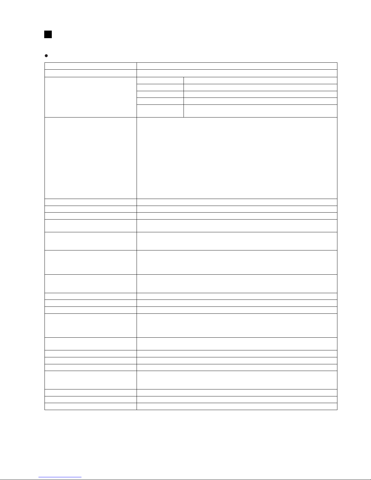
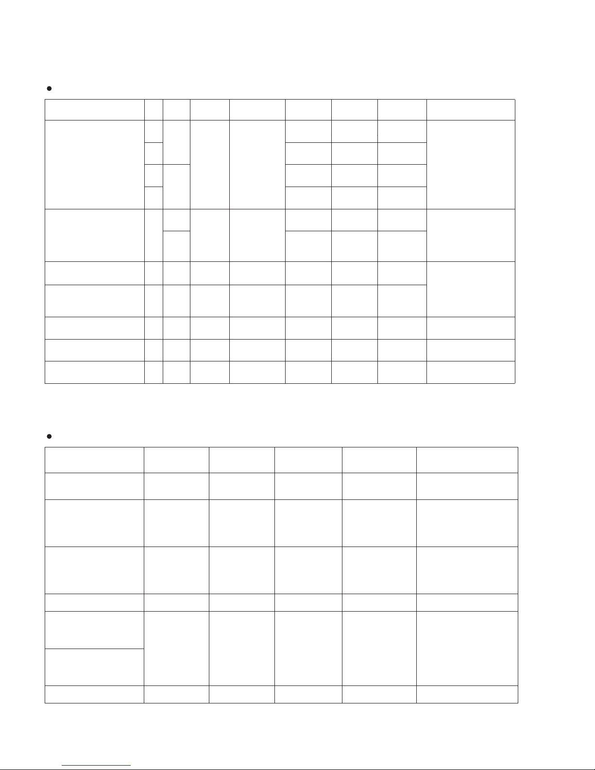
General Specifications
Where 0 dBu = 0.775 V and 0 dBV= 1 V
1
Rs = 150 ohms
Measured with 12.7 kHz, –6 dB/oct. low pass filter (equivalent to 20 kHz, –∞filter).
2
Turning PAN/BAL to left or right.
3
Shelving turnover/rolloff frequency: 3 dB before maximum cut or boost.
Frequency Characteristics (Master Output) 20 Hz–20 kHz +1 dB, –3 dB @+4 dBu, 600
Ω
(with gain control at minimum level)
Total Harmonic Distortion (Master Output) 0.1% (THD+N) @+14 dBu, 20 Hz–20 kHz, 600
Ω
(with gain control at maximum level)
Hum and Noise (20 Hz - 20 kHz)
1
Input GAIN = Maximum
Input PAD = OFF
Input sensitivity = –60 dBu
–128 dBu
Equivalent input noise (CHs 1 to 24 (MG32/14FX)/CHs 1 to 16 (MG24/14FX))
–99 dBu
Residual output noise (ST, MONO OUT, AUX, EFFECT, GROUP OUT)
–83 dBu (87 dB S/N)
ST, MONO, GROUP Master fader at nominal level; all Ch assign switches off.
–78 dBu (82 dB S/N)
AUX master control at nominal level; all channel mix controls at minimum level.
–64 dBu (68 dB S/N)
ST, GROUP Master fader and one Ch fader at nominal level.
(CHs 1 to 24 (MG32/14FX)/CHs 1 to 16 (MG24/14FX))
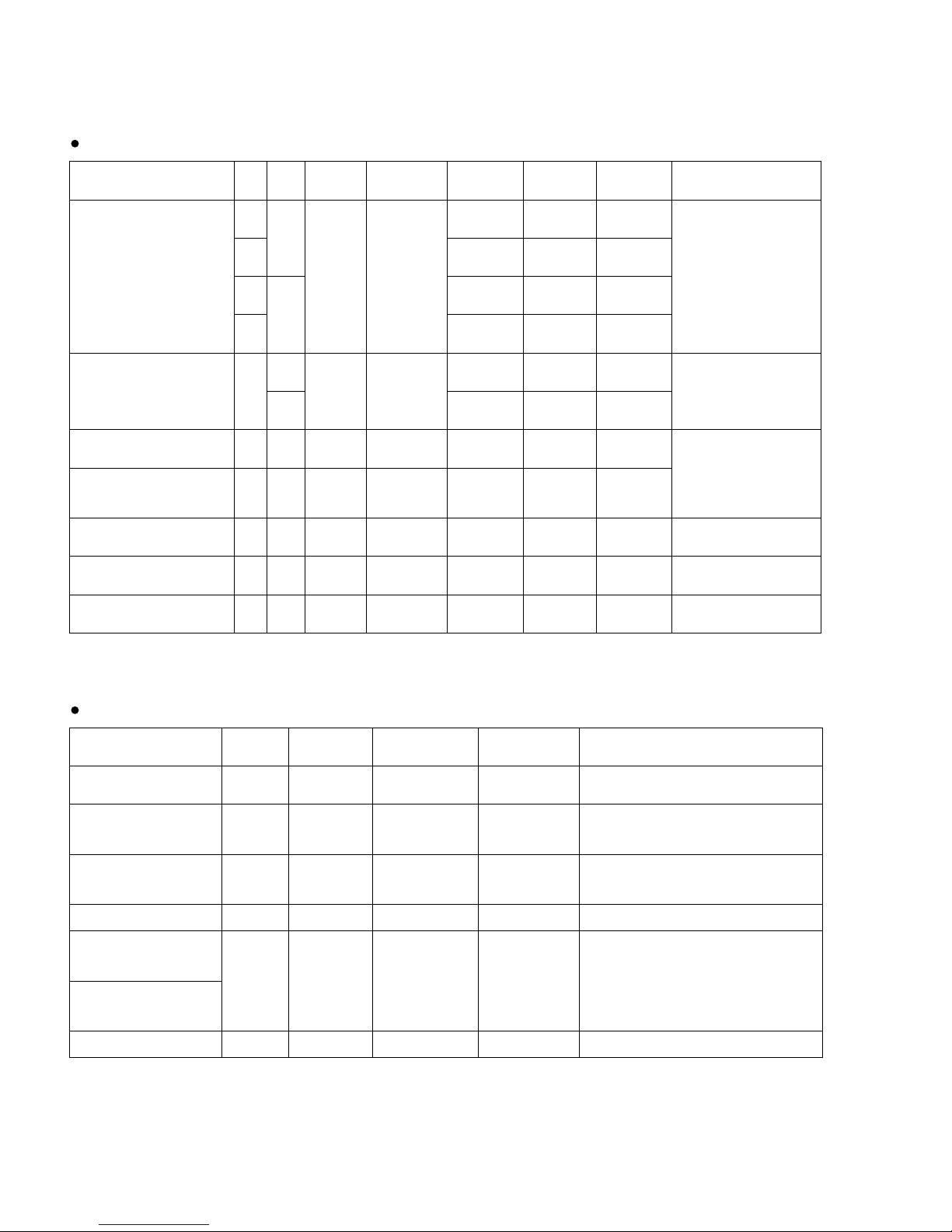
Maximum Voltage Gain
2
60 dB CH IN
→
CH INSERT OUT
84 dB CH IN
→
GROUP OUT/ST OUT (CH to ST)
94 dB CH IN
→
ST OUT (GROUP to ST)
70 dB CH IN
→
GROUP INSER OUT, ST INSERT OUT (CH to ST)
62.2 dB CH IN
→
REC OUT (CH to ST)
76 dB CH IN
→
AUX SEND (PRE)
86 dB CH IN
→
AUX SEND (POST)/EFF SEND
80 dB CH IN
→
ST SUB OUT (CH to ST)
58 dB ST CH IN
→
GROUP OUT/ST OUT (ST CH to ST)
47 dB ST CH IN
→
AUX SEND (PRE)
57 dB ST CH IN
→
AUX SEND (POST)/EFF SEND
16 dB RETURN
→
ST OUT
9 dB RETURN
→
AUX SEND
27.8 dB 2TR INPUT
→
ST OUT
Monaural/Stereo Input Gain Control 44 dB variable
Monaural High Pass Filter 80 Hz 12 dB/octave
Channel Input PAD 0 dB/26 dB
Crosstalk (1 kHz) –70 dB between input channels
–70 dB between input/output channels (CH INPUT)
Monaural Input Channel Equalization:
Max. Variation (CHs 1 to 8)
3
±15 dB HIGH 10 kHz shelving
MID 0.25–5 kHz peaking
LOW 100 Hz shelving
Stereo Input Channel Equalization:
Max. Variation (CHs 9/10 to 15/16)
3
±15 dB HIGH 10 kHz shelving
HI-MID 3 kHz peaking
LO-MID 800 Hz peaking
LOW 100 Hz shelving
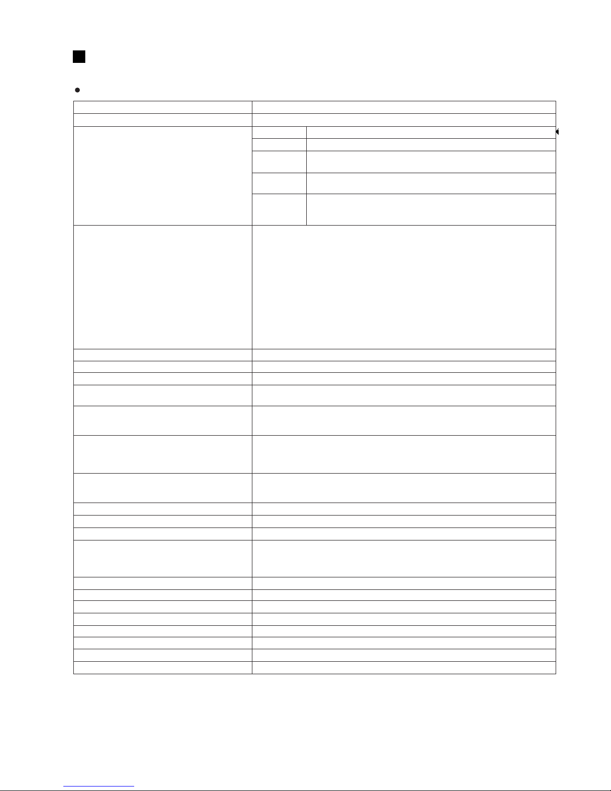
Internal Digital Effects Effect 1: 16 programs, parameter control
Effect 2: 16 programs, parameter control
TAP DELAY Control, Foot Switch (TAP)
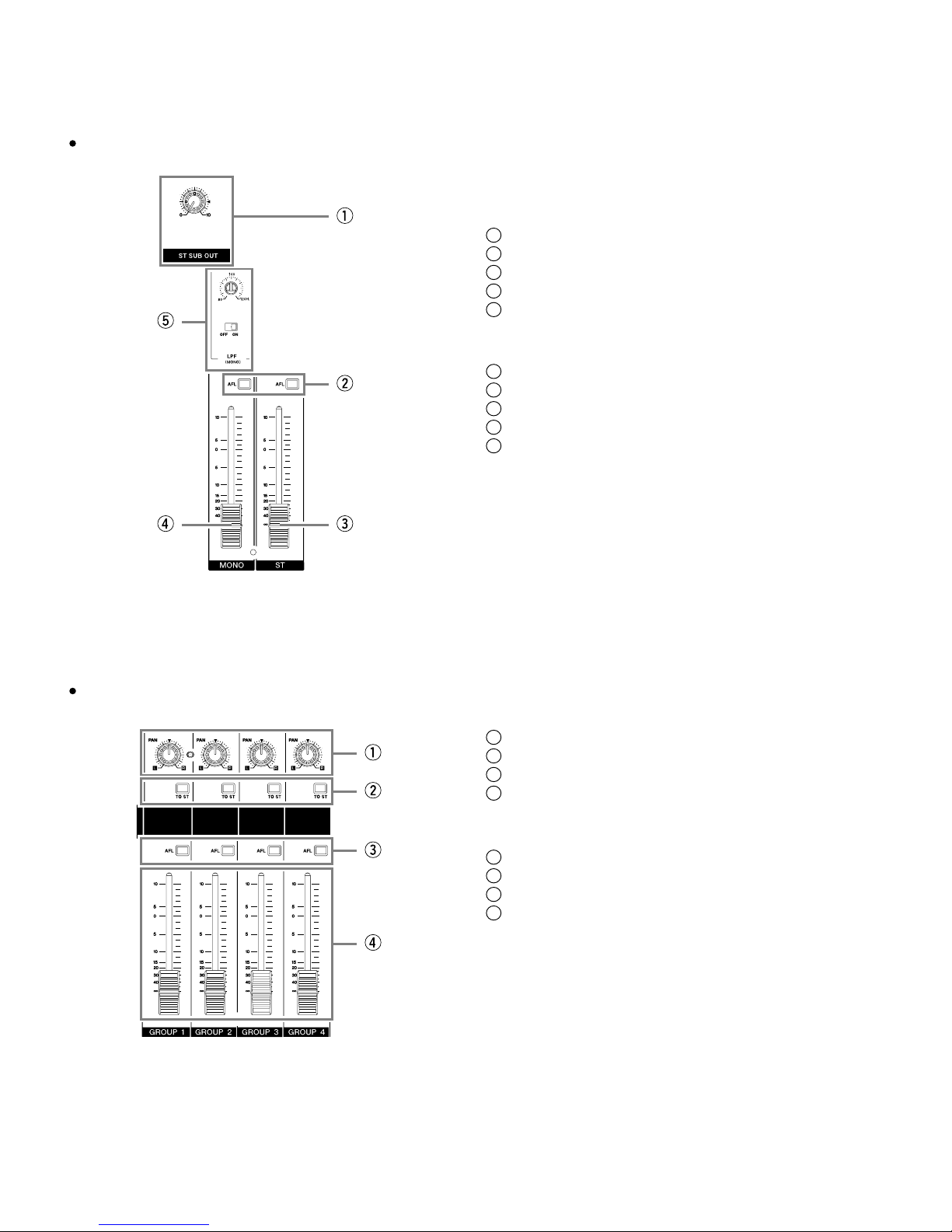
MONO Low Pass Filter 80 - 120 Hz 12 dB/octave
Monaural/Stereo Input Peak Indicator One red LED per channel. Comes on when post-EQ signal level reaches +17 dBu.
Monaural/Stereo Input Signal Indicator One green LED per channel. Comes on when post-EQ signal level reaches –10 dBu.
Level Meters
Four 12-point LED meters [Stereo (L, R), PFL/AFL, GROUP (1 - 4)]
Peak point: red indicator
+5, +3, +1, and 0 points: yellow indicators
–1, –3, –5, –7, –10, –15, –20: green indicators
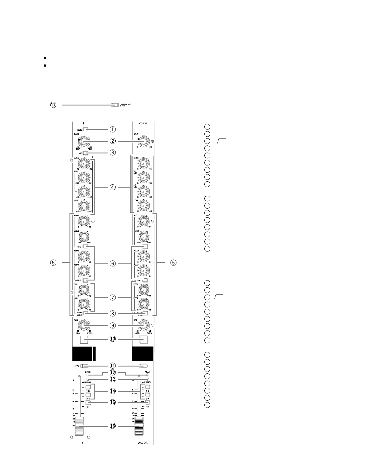
Phantom +48 VDC Power
(Balanced input) +48 V DC supply to balanced inputs. Can be switched ON/OFF in groups of eight channels.
(One switch for every eight channels.)
Included Accessory Power cord, Owner’s Manual
Option FC5 (Foot Switch)
Lamp XLR-3-31 type (12 V AC between pins 2 and 3; 0.5 A max. rating )
Power Supply USA and Canada: 120 V AC, 60 Hz
Korea: 220 V AC, 60 Hz
Others: 230 V AC, 50 Hz
Power Consumption MG32/14FX: 120 W, MG24/14FX: 100 W
Max. Dimensions (W
×
H
×
D) MG32/14FX: 1027
×
140
×
551 mm, MG24/14FX: 819
×
140
×
551 mm
Weight MG32/14FX: 22 kg, MG24/14FX: 18.5 kg
<
=

MG24/14FX
MG32/14FX
4
Input Specifications
Where 0 dBu = 0.775 V and 0 dBV= 1 V
1Input sensitivity: the lowest level that will produce the nominal output level when the unit is set to maximum gain.
2MG32/14FX: CH29(L)/30(R), CH31(L)/32(R), MG24/14FX: CH21(L)/22(R), CH23(L)/24(R)
Output Specifications
Where 0 dBu = 0.775 V and 0 dBV= 1 V
Input Connector PAD Gain Input
Impedance Appropriate
Impedance Sensitivity 1Rated Level Max. Before
Clipping Connector
Specifications
CH INPUT (A, B)
(MG32/14FX: CHs 1 to 24)
(MG24/14FX: CHs 1 to 16)
0–60
3 kΩ50–600 Ωmic
600 Ωline
–80 dBu
(0.078 mV) –60 dBu
(0.775 mV) –40 dBu
(7.75 mV)
A: XLR-3-31 type (bal-
anced)
B: Phone jack (TRS)
(balanced
[T: hot; R: cold; S: ground])
26 –54 dBu
(1.55 mV) –34 dBu
(15.5 mV) –14 dBu
(155 mV)
0–16
–36 dBu
(12.3 mV) –16 dBu
(123 mV) +4 dBu
(1.23 V)
26 –10 dBu
(245 mV) +10 dBu
(2.45 V) +30 dBu
(24.5 V)
ST CH INPUT
(MG32/14FX:CHs25(L)/26(R)
to 31(L)/32(R))
(MG24/14FX:CHs17(L)/18(R)
to 23(L)/24(R))
–34 10 kΩ600 Ωline
–54 dBu
(1.55 mV) –34 dBu
(15.5 mV) –14 dBu
(155 mV) Phone jack (unbalanced),
RCA pin jack 2
+10 –10 dBu
(245 mV) +10 dBu
(2.45 V) +30 dBu
(24.5 V)
ST INSERT IN [L, R]
GROUP INSERT IN (1 - 4) 10 kΩ600 Ωline –10 dBu
(245 mV) 0 dBu
(0.775 V) +20 dBu
(7.75 V) Phone jack (TRS)
(unbalanced
[T: out; R: in; S: ground])
CH INSERT IN
(MG32/14FX: CHs 1 to 24)
(MG24/14FX: CHs 1 to 16) 10 kΩ600 Ωline –20 dBu
(77.5 mV) 0 dBu
(0.775 V) +20 dBu
(7.75 V)
RETURN (1, 2) (L, R) 10 kΩ600 Ωline –12 dBu
(195 mV) +4 dBu
(1.23 V) +24 dBu
(12.3 V) Phone jack (TRS)
(unbalanced)
TALK BACK 10 kΩ50 - 600 Ω
mic –66 dBu
(0.388 mV) –50 dBu
(2.45 mV) –30 dBu
(24.5 mV) XLR-3-31 type
(unbalanced)
2TR IN (L, R) 10 kΩ600 Ωline –26 dBV
(50.1 mV) –10 dBV
(316 mV) +10 dBV
(3.16 V) RCA pin jack
Output Connectors Output
Impedance Appropriate
Impedance Rated Level Max. Before
Clipping Connector Specifications
ST OUT (L, R)
MONO 150 Ω600 Ωline +4 dBu (1.23 V) +24 dBu (12.3 V) XLR-3-32 type (balanced)
GROUP OUT (1-4)
AUX SEND (1-6) 150 Ω600 Ωline +4 dBu (1.23 V) +20 dBu (7.75 V) Phone jack (TRS)
(impedance balanced [T: hot; R: cold; S:
ground])
ST SUB OUT (L, R)
EFFECT SNED (1, 2) 150 Ω10 kΩline +4 dBu (1.23 V) +20 dBu (7.75 V) Phone jack (TRS)
(impedance balanced [T: hot; R: cold; S:
ground])
REC OUT (L, R) 600 Ω10 kΩline –10 dBV (316 mV) +10 dBV (3.16 V) RCA pin jack
CH INSERT OUT
(MG32/14FX: CH 1- 24)
(MG24/14FX: CH 1- 16) 150 Ω10 kΩline 0 dBu (0.775 V) +20 dBu (7.75 V) Phone jack (TRS)
(unbalanced [T: out; R: in; S: ground])
GROUP INSERT OUT
(1-4)
ST INSERT OUT (L, R)
PHONES 100 Ω40 Ωphone 3 mW 75 mW Stereo phone jack

MG24/14FX
MG32/14FX
5
総合仕様
一般仕様
* 0 dBu=0.775V、0 dBV=1 V とする
*1 Rs=150 ohms
@12.7 kHz、–6 dB/oct. のローパスフィルターにて測定(@20 kHz、–∞dB/oct.フィルターに相当)
*2 PAN/BAL 左か右へ回す
*3 シェルビングタイプのターンオーバー/ロールオフ周波数:最大可変幅に対し3 dB下がったポイント
周波数特性(Master Output)
20 Hz 〜
20 kHz +1 dB、
–3 dB
@
+4 dBu(
*)、600 Ω(GAIN コントロール=最
小
レベル)
全高調波歪率(Master Output)
0.1 %(
THD+N)
@+14 dBu、
20 Hz 〜
20 kHz、
600 Ω(GAIN コントロール=最大レベル)
ハム & ノイズ(20 Hz~20 kHz)
Input GAIN = Maximum
Input PAD = OFF
Input sensitivity = –60 dBu
–128 dBu 入力換算ノイズ
(
CH1
〜
24
(
MG32/14FX
)
/CH1
〜16
(
MG24/14FX
)
)
–99 dBu 残留ノイズ(ST
、
MONO OUT
、
AUX
、
EFFECT
、
GROUP OUT)
–83 dBu
(87 dB S/N)ST、MONO、GROUP
マスターフェーダー=ノミナル、全チャンネルアサインスイッチ= OFF
–78 dBu
(82 dB S/N)
AUX マスターコントロール=ノミナル、全チャンネル
ミックスコントロール=最小レベル
–64 dBu
(68 dB S/N)
ST、GROUP
マスターフェーダー&1 チャンネルフェーダー=ノミナル
(
CH1
〜
24
(
MG32/14FX
)
/ CH1 〜16
(
MG24/14FX
))
最大電圧ゲイン
*2
60 dB
CH IN →
CH INSERT OUT
84 dB
CH IN →
GROUP OUT/ST OUT(CH to ST)
94 dB
CH IN →
ST OUT(GROUP to ST)
70 dB
CH IN →GROUP INSERT OUT
、
ST INSERT OUT(CH to ST)
62.2 dB
CH IN→
REC OUT(CH to ST)
76 dB
CH IN →AUX SEND(PRE)
86 dB
CH IN →
AUX SEND(POST)/EFF SEND
80 dB
CH IN →
ST SUB OUT(CH to ST)
58 dB
ST CH IN →GROUP OUT/ST OUT(ST CH to ST)
47 dB
ST CH IN →AUX SEND(PRE)
57 dB
ST CH IN →
AUX SEND(POST)/EFF SEND
16 dB
RETURN →ST OUT
9 dB
RETURN →
AUX SEND
27.8 dB
2TR IN →ST OUT
モノラル、ステレオインプットゲインコントロール
44 dB 可変
モノラルハイパスフィルター 80 Hz 12 dB/octave
チャンネル入力 PAD 0 dB/26 dB
クロストーク(1 kHz)–70 dB 入力チャンネル間
–70 dB 入出力チャンネル間(CH INPUT)
モノラル入力チャンネルイコライザー特性最大可
変幅(CH1
〜
8)
*3
±15 dB HIGH 10 kHz シェルビングタイプ
MID 0.25 〜5 kHz ピーキングタイプ
LOW 100 Hz シェルビングタイプ
ステレオ入力チャンネルイコライザー特性最大可
変幅(CH9/10
〜
15/16)
*3
±15 dB HIGH 10 kHz シェルビングタイプ
HI-MID 3 kHz ピーキングタイプ
LO-MID 800 Hz ピーキングタイプ
LOW 100 Hz シェルビングタイプ
内蔵デジタルエフェクト エフェクト 1:16 種類、パラメーターコントロール
エフェクト 2:16 種類、パラメーターコントロール、
TAP DELAY コントロール、フットスイッチ (TAP)
MONO ローパスフィルター
80 〜120 Hz 12 dB/octave
モノラル、ステレオインプットピークインジケーター
各チャンネル、イコライザーの後段において、信号レベルが +17 dBu に達すると赤く点灯
モノラル、ステレオインプットシグナルインジケーター
各チャンネル、イコライザーの後段において、信号レベルが –10 dBu に達すると緑に点灯
レベルメーター 12 ポイントLED ×4 [ステレオ(
L、
R)、
PFL/AFL、
GROUP(
1~4)]
ピーク時:赤のインジケーター
+5、+3、+1、0:黄のインジケーター
–1、–3、–5、–7、–10、–15、–20:緑のインジケーター
ファンタム電源 +48 VDC(バランス入力) PHANTOM +48 V スイッチ= ON で8 チャネルごとに供給
付属品 電源コード、取扱説明書、保証書
オプション FC5(フットスイッチ)
ランプ端子 XLR-3-31 type(2-3 pin 間にAC12 Vを供給、最大定格 0.5 A)
電源 100 V AC 50/60 Hz
消費電力 MG32/14FX:120 W、MG24/14FX:100 W
最大外形寸法(W ×H ×D)MG32/14FX:W1027 ×H140 ×D551 mm、MG24/14FX:W819 ×H140 ×D551 mm
質量 MG32/14FX:22 kg、MG24/14FX:18.5 kg
<
=
*1

MG24/14FX
MG32/14FX
6
入力仕様
* 0dBu=0.775V、0dBV=1Vとする
*1 入力感度:最大ゲイン測定時に定格出力が得られる最小レベル
*2 MG32/14FX:CH29(L)/30(R)、CH31(L)/32(R)、MG24/14FX: CH21(L)/22(R)、CH23(L)/24(R)
出力仕様
* 0 dBu=0.775 V、0 dBV=1 V とする
入力端子名称 PAD ゲイン入力イン
ピーダンス 適合
インピーダンス 感度*1 規定レベル 最大ノンク
リップレベル 端子仕様
CH INPUT(A、B)
(MG32/14FX:CH1 〜24)
(MG24/14FX:CH1 〜16)
0–60
3 kΩ
50〜600 Ω
マイク
600 Ωライン
–80 dBu
(
0.078 mV)
–60 dBu
(
0.775 mV)–40 dBu
(
7.75 mV) A:XLR-3-31タイプ
(バランス型)
B: フォーンジャック
(TRS)
(バランス型
[T:ホット、R: コール
ド、S:グラウンド])
26 –54 dBu
(
1.55 mV)
–34 dBu
(
15.5 mV)–14 dBu
(
155 mV)
0
–16
–36 dBu
(
12.3 mV)
–16 dBu
(
123 mV) +4 dBu
(
1.23 V)
26
–10 dBu
(
245 mV)
+10 dBu
(
2.45 V) +30 dBu
(
24.5 V)
ST CH INPUT
(
MG32/14FX:CH25(L)/26(R)
〜CH31(L)/32(R))
(
MG24/14FX:CH17(L)/18(R)
〜CH23(L)/24(R))
–34 10 kΩ
600 Ωライン –54 dBu
(
1.55 mV)
–34 dBu
(
15.5 mV)–14 dBu
(
155 mV) フォーンジャック
(アンバランス型)
RCA ピックジャック
*2
+10 –10 dBu
(
245 mV)
+10 dBu
(
2.45 V) +30 dBu
(
24.5 V)
ST INSERT IN [L、
R]
GROUP INSERT IN(
1~4)
10 kΩ
600 Ωライン –10 dBu
(
245 mV)
0 dBu
(
0.775V) +20 dBu
(
7.75 V)
フォーンジャック(TRS)
(アンバランス型
[
T:アウト、
R:イン、
S:グラウンド])
CH INSERT IN
(
MG32/14FX:CH1〜24)
(
MG24/14FX:CH1〜16)
10 kΩ
600 Ωライン –20 dBu
(
77.5 mV)
0 dBu
(
0.775 V) +20 dBu
(
7.75 V)
RETURN (1、2)(L、R)
10 kΩ 600 Ωライン –12 dBu
(
195 mV)
+4 dBu
(
1.23 V) +24 dBu
(
12.3 V)
フォーンジャック(TRS)
(アンバランス型)
TALK BACK 10 kΩ
50〜600 Ω
マイク
–66 dBu
(
0.388 mV)
–50 dBu
(
2.45 mV)–30 dBu
(
24.5 mV) XLR-3-31 タイプ
(アンバランス型)
2TR IN (
L、
R)
10 kΩ 600 Ωライン –26 dBV
(
50.1 mV)
–10 dBV
(
316 mV) +10 dBV
(
3.16 V)
RCA ピンジャック
出力端子名称
出力
インピーダンス 適合
インピーダンス
規定レベル 最大
ノンクリップレベル 端子仕様
ST OUT
(
L、R
)
MONO
150 Ω 600 Ωライン +4 dBu(
1.23 V)+24 dBu(
12.3 V)
XLR-3-32 タイプ(バランス型)
GROUP OUT(1 〜4)
AUX SEND(1 〜6)
150 Ω
600 Ωライン +4 dBu(
1.23 V)+20 dBu(
7.75 V) フォーンジャック(TRS)
(インピーダンスバランス型
[T:ホット、R: コールド、
S: グラウンド])
ST SUB OUT(L、R)
EFF SEND(1、2)
150 Ω
10 kΩライン +4 dBu(
1.23 V)+20 dBu(
7.75 V) フォーンジャック(TRS)
(インピーダンスバランス型
[T:ホット、R: コールド、
S: グラウンド])
REC OUT(L
、
R)
600 Ω 10 kΩライン
–10dBV(316mV)
+10dBV(3.16V)
RCAピンジャック
CHINSERTOUT
(
MG32/14FX:CH1〜
24)
(
MG24/14FX:CH1〜16)
150Ω
10kΩライン +0dBu(0.775V)
+20dBu(7.75V)
フォーンジャック(TRS)
(アンバランス型
[T:アウト、R:イン、
S: グラウンド])
GROUPINSERTOUT
(1〜4)
STINSERTOUT(L
、
R)
PHONES 100Ω
40Ωフォーン 3mW 75mW ステレオフォーンジャック

MG24/14FX
MG32/14FX
7
DIMENSIONS
Units: mm
(単位)
Units: mm
(単位)
(寸法図)
MG32/14FX
1027
765 98.5
101
140
551
415 48
MG24/14FX
819
98.5
557
101
140
551
415 48

MG24/14FX
MG32/14FX
8
11
8
10
342
76 5
1
9
8
Note: Within this manual, all panel illustrations show the MG32/14FX panel.
(本書中のイラストはすべてMG32/14FXです。)
PANEL LAYOUT
1
2
3
4
5
6
7
8
9
10
11
MONAURAL CHANNELS Section (p. 9)
STEREO CHANNELS Section (p. 9)
STEREO/MONO Section (p. 10)
GROUP Section (p. 10)
SEND Section (p. 11)
RETURN Section (p. 11)
INTERNAL DIGITAL EFFECTS Section (p. 12)
METER/PHONES Section (p. 13)
2TR INPUT Section (p. 13)
TALKBACK Section (p. 14)
LAMP Jack (p. 14)
12
13 CHANNEL I/O Section (p. 14)
MASTER I/O Section (p. 15)
Channel Control Block
Master Control Block
チャンネルコントロール部
Rear Input/Output Block リア入出力部
1
2
3
4
5
6
7
8
9
10
11
Rear Panel(リアパネル)
Front Panel(フロントパネル)
12
13 チャンネル入出力セクション(P14)
マスター入出力セクション(P15)
モノラルチャンネルセクション(P9)
ステレオチャンネルセクション(P9)
ST/MONOセクション(P10)
GROUPセクション(P10)
SENDセクション(P11)
RETURNセクション(P11)
内蔵デジタルエフェクトセクション(P12)
メーター/PHONESセクション(P13)
2TR入力セクション(P13)
トークバックセクション(P14)
LAMP端子(P14)
マスターコントロール部
(パネルレイアウト)
1213

MG24/14FX
MG32/14FX
9
1
2
3
4
5
6
7
8
9
10
11
12
13
14
15
16
17
1
2
3
4
5
6
7
8
9
10
11
12
13
14
15
16
17
Monaural Channels
1 to 24 (MG32/14FX)
1 to 16 (MG24/14FX)
Stereo Channels
(モノラルチャンネル) (ステレオチャンネル)
25/26 to 31/32 (MG32/14FX)
17/18 to 23/24 (MG24/14FX)
[PAD] Switch
[GAIN] Control
[ 80 ] Switch (High-Pass Filter)
[Equalizer] Controls
[AUX] Controls ([AUX1] to [AUX6])
[PRE] Switch
[EFFECT] Controls
[AUX5], [AUX6] Switch
[PAN] Control (Monaural Channels)
[BAL] Control (Stereo Channels)
[ON] Switch
[PFL] (Pre-Fader Listen) Switch
[PEAK] indicator
[SIGNAL] indicator
[GROUP] Switches
[ST] Switch
[Channel] Fader
[PHANTOM +48 V] Switch
[PAD]スイッチ
[GAIN]コントロール
[80](ハイパスフィルター)スイッチ
[イコライザー]コントロール
[AUX]コントロール([AUX1]〜[AUX6])
[PRE]スイッチ
[EFFECT]コントロール
[AUX5]、[AUX6]スイッチ
[PAN]コントロール(モノラルチャンネル)
[BAL]コントロール(ステレオチャンネル)
[ON]スイッチ
[PFL]スイッチ(Pre‐FaderListen)
[PEAK]インジケーター
[SIGNAL]インジケーター
[GROUP]スイッチ
[ST]スイッチ
[チャンネル]フェーダー
[PHANTOM+48V]スイッチ
MONAURAL CHANNELS Section
STEREO CHANNELS Section (モノラルチャンネルセクション)
(ステレオチャンネルセクション)

MG24/14FX
MG32/14FX
10
1
2
3
4
5
1
2
3
4
5
[ST SUB OUT] Control
[AFL] (After-Fader Listen) Switch
[ST Master] Fader
[MONO] Fader
LPF (MONO)
[STSUBOUT]コントロール
[AFL]スイッチ(After‐FaderListen)
[STマスター]フェーダー
[MONO]フェーダー
LPF(MONO)
1
2
3
4
1
2
3
4
[PAN] Control
[TO ST] Switches
[AFL] (After-Fader Listen) Switches
[Group] Faders
[PAN]コントロール
[TOST]スイッチ
[AFL]スイッチ(After‐FaderListen)
[GROUP]フェーダー(1〜4)
STEREO/MONO Section
(ST/MONOセクション)
GROUP Section
(GROUPセクション)

MG24/14FX
MG32/14FX
11
1
2
3
1
2
3
[AUX] Controls ([AUX1] to [AUX6])
[Effect] Controls (EFF1, EFF2)
[AFL] (After-Fader Listen) Switches
[AUX]コントロール([AUX1]〜[AUX6])
[EFF]コントロール(1、2)
[AFL]スイッチ(After‐FaderListen)
1
2
3
1
2
3
[AUX Mix] Controls (1 to 4)
[ST] Control
[PFL] (Pre-Fader Listen) Switch
[AUX]ミックスコントロール(1〜4)
[ST]コントロール
[PFL]スイッチ(Pre‐FaderListen)
SEND Section(SENDセクション)
RETURN Section(RETURNセクション)

MG24/14FX
MG32/14FX
12
1
2
3
4
5
6
7
8
9
1
2
3
4
5
6
7
8
9
[PROGRAM] Dials
[PARAMETER] Controls
[AUX PRE] Controls ([AUX1] to [AUX4])
[TAP] Button and Indicator
[ON] Switches
[PFL] (Pre-Fader Listen) Switches
[GROUP] Switches
[ST] Switches
[EFFECT RTN] faders (1, 2)
[PROGRAM選択]ダイアル
[パラメーター]コントロール
[AUXPRE]コントロール([AUX1]〜[AUX4])
[TAP]ボタン、インジケーター
[ON]スイッチ
[PFL]スイッチ(Pre‐FaderListen)
[GROUP]スイッチ(1‐2、3‐4)
[ST]スイッチ
[EFFECTRTN]フェーダー(1、2)
INTERNAL DIGITAL EFFECTS Section
(内蔵デジタルエフェクトセクション)

MG24/14FX
MG32/14FX
13
METER/PHONES Section
(メーター/PHONESセクション)
2TR INPUT Section
(2TR入力セクション)
1
2
3
4
5
1
2
3
4
5
[POWER] Indicator
[STEREO Level] Meters
[PFL-AFL Level] Meters
[GROUP] Switch
[PHONES] Jack and Control
[POWER]インジケーター
[STEREO]レベルメーター
[PFL‐AFL]レベルメーター
[GROUP]スイッチ
[PHONES]
1
2
1
2[2TR IN] Control
[PFL] (Pre-Fader Listen) Switch
[2TRIN]コントロール
[PFL]スイッチ(Pre‐FaderListen)

MG24/14FX
MG32/14FX
14
TALKBACK Section
(トークバックセクション) LAMP jack
(LAMP端子)
1
2
3
4
1
2
3
4
[MIC] Jack
[Talkback] Control
[AUX1] - [AUX4] Switch
[ST] Switch
[MIC]端子
[トークバック]コントロール
[AUX]スイッチ([AUX1]〜[AUX4])
[ST]スイッチ
[LAMP] Jack
[LAMP]端子
CHANNEL I/O Section(チャンネル入出力セクション)
1
2
3
1
2
3
[Monaural-Channel Input] Jacks
(MG32/14FX: CHs 1 to 24, MG24/14: CHs 1 to 16)
[INSERT I/O] Jacks
[Stereo-Channel Input] Jacks
(MG32/14FX: CHs 25/26, 27/28, 29/30, 31/32)
(MG24/14FX: CHs 17/18, 19/20, 21/22, 23/24)
[モノラルチャンネル入力]端子
(MG32/14FX:CH1〜24、MG24/14:CH1〜16)
[INSERTI/O]端子
[ステレオチャンネル入力]端子
(MG32/14FX:CH25/26、27/28、29/30、31/32)
(MG24/14FX:CH17/18、19/20、21/22、23/24)

MG24/14FX
MG32/14FX
15
MASTER I/O Section
(マスター入出力セクション)
1
2
3
4
5
6
7
8
9
10
11
12
13
1
2
3
4
5
6
7
8
9
10
11
12
13
[RETURN] Jacks (1, 2)
[2TR IN] Jacks
[REC OUT] (L, R) Jacks
[SEND] Jacks
[GROUP INS I/O] Jacks (1 to 4)
[GROUP OUT] Jacks (1 to 4)
[ST INSERT I/O] (L, R) Jacks
[ST SUB OUT] Jacks (L and R)
[ST OUT] Jacks (L, R)
[MONO] Jack
[FOOT SWITCH TAP] Jack
[POWER] Switch
[AC IN] Connector
[RETURN]端子(1、2)
[2TRIN]端子
[RECOUT](L、R)端子
[SEND]端子
[GROUPINSI/O]端子(1〜4)
[GROUPOUT](1〜4)端子
[STINSERTI/O]端子(L、R)
[STSUBOUT]端子
[STOUT](L、R)端子
[MONO]端子
[FOOTSWITCHTAP]端子
[POWER]スイッチ
[ACIN]端子

MG24/14FX
MG32/14FX
16
Connector Polarities
*These jacks also accept connection to monaural phone plugs. If you use monaural plugs, the connection will be unbalanced.
INPUT A, ST OUT, MONO Pin 1: Ground
Pin 2: Hot (+)
Pin 3: Cold (–)
MIC (Talkback) Pin 1: Ground
Pin 2: Hot (+)
Pin 3: Ground
INPUT B, GROUP OUT, AUX SEND (1 to 6),
EFFECT SEND (1, 2), ST SUB OUT*
Tip: Hot (+)
Ring: Cold (–)
Sleeve: Ground
INSERT I/O,
GROUP INS I/O, ST INSERT I/O
Tip: Output
Ring: Input
Sleeve: Ground
PHONES Tip: L
Ring: R
Sleeve: Ground
Stereo channel input jacks,
RETURN (1, 2) Tip: Hot
Sleeve: Ground
Stereo channel input jacks,
2TR IN,
REC OUT
INPUT OUTPUT
INPUT
Ring
Sleeve Tip
Sleeve Tip
Sleeve Tip
端子接続の極性
(*)これらの端子に、モノラルタイプのフォーン端子を使用することもできます。その場合は、アンバランスになります。
INPUT A、ST OUT、MONO ピン 1:グラウンド
ピン 2:ホット(+)
ピン 3:コールド(–)
MIC(トークバック) ピン 1:グラウンド
ピン 2:ホット(+)
ピン 3:グラウンド
INPUT B、
GROUP OUT、
AUX SEND (
1〜6)
、
EFF SEND(
1、
2)、ST SUB OUT(*)
チップ:ホット(+)
リング:コールド(–)
スリーブ:グラウンド
INSERT I/O、
GROUP INS I/O、ST INSERT I/O
チップ:Output
リング:Input
スリーブ:グラウンド
PHONES チップ:L
リング:R
スリーブ:グラウンド
ステレオチャンネル入力端子、
RETURN(1、2)チップ:ホット
スリーブ:グラウンド
ステレオチャンネル入力端子、
2TR IN、
REC OUT
INPUT OUTPUT
INPUT
スリーブ チップ
リング
スリーブ チップ
スリーブチップ

MG24/14FX
MG32/14FX
17
CIRCUIT BOARD LAYOUT
(ユニットレイアウト)
MG32/14FX
INJK INJK INJK
(INJK1) (INJK2) (INJK3)
PS PSDSP DSP
IN IN IN(IN1) (IN2) (IN3) MAS
MASJK
MAS 1/4
MAS 2/4
MAS 3/4
MAS 4/4
MG24/14FX
INJK INJK(INJK1) (INJK2)
PS PSDSP DSP
IN IN(IN1) (IN2) MAS 1/4
MAS 2/4
MAS 3/4
MAS 4/4
MASJK

MG24/14FX
MG32/14FX
18
WIRING
(結線図)
INJK
INJK
INJK
(INJK1)
(INJK2)
1ch
8ch
(INJK3)
PS
DSP
IN
IN
IN
(IN1)
(IN2)
(IN3)
MASJK
MAS 1/4
CN101
CN105 CN105
CN101
CN102
CN103
CN104
CN101
CN102
CN103
CN104
CN106
CN107
CN109
CN108
CN111
CN110
CN105 CN105
CN101
CN102
CN103
CN104
CN101
CN102
CN103
CN104
CN106
CN107
CN109
CN108
CN111
CN110
CN105 CN105
CN101
CN102
CN103
CN104
CN701
CN103
CN104
CN105
CN102
CN101
Transformer
Transformer
AC-SW
CN100
CN101
CN201
CN301
CN401
CN501
CN601
CN502 CN902
CN901
CN908 CN907 CN906
CN101
CN501
CN601
CN503
CN701
CN702
CN801
CN101
CN102
CN103
CN104
CN106
CN107
CN109
CN108
CN111
CN110
CN903
CN905
CN904 CN301 CN302
MAS 2/4 MAS 3/4 MAS 4/4
MG32/14FX
~
9ch
16ch
~
17ch
24ch
~
25ch
32ch
~

MG24/14FX
MG32/14FX
19
INJK
INJK
(INJK1)
(INJK2)
PS
DSP
IN
IN
(IN1)
(IN2)
MASJK
MAS 1/4
CN101
CN105 CN105
CN101
CN102
CN103
CN104
CN101
CN102
CN103
CN104
CN106
CN107
CN109
CN108
CN111
CN110
CN105 CN105
CN101
CN102
CN103
CN104
CN701
CN103
CN104
CN105
CN102
CN101
Transformer
Transformer
AC-SW
CN100
CN101
CN201
CN301
CN401
CN501
CN601
CN502 CN902
CN901
CN908 CN907 CN906
CN101
CN501
CN601
CN503
CN701
CN702
CN801
CN101
CN102
CN103
CN104
CN106
CN107
CN109
CN108
CN111
CN110
CN903
CN905
CN904 CN301 CN302
MAS 2/4 MAS 3/4 MAS 4/4
MG24/14FX
1ch
8ch
~
9ch
16ch
~
17ch
24ch
~

MG24/14FX
MG32/14FX
20
1. Overview
(概観)
(ACインレット&PSWAss'y)
6
7
4
3
5
2
33
6
7
4
3
5
2
33
2-1.
Assembly of AC-INLET & POWER-SW
190:WA782600
270: (WA61030)
260:WA609600
915:WB071100
250: (WA60980)
280:VV314800
2-2. Detail of lead-wire treatment
(ワイヤー処理の詳細)
two turn
one turn
(This picture is state of before soldering.)
(この写真は接合する前の状態です)
(熱収縮チューブを備えた、ハンダおよびカバー(5箇所))
2-3. Solder and cover with heat-shrink-tube (five places)
15mm ±2mm
15mm ±2mm
※Cover firmly to a root.
(根元までしっかりカバー
をしてください)
※
※
2-4. Set PS-HOLDER
(PSホルダーのセット)
210:WA677500
2-5. Set to Panel
(パネルへのセット)
230:VP184000
This manual suits for next models
1
Table of contents
Other Yamaha Music Mixer manuals

Yamaha
Yamaha MC1204 II User manual

Yamaha
Yamaha powered mixer User manual

Yamaha
Yamaha Ncs500-FD User manual

Yamaha
Yamaha 01V96i User manual

Yamaha
Yamaha EMX860ST User manual

Yamaha
Yamaha 12/4 User manual

Yamaha
Yamaha PM5D User manual

Yamaha
Yamaha AG03MK2 User manual

Yamaha
Yamaha MG12/4 User manual

Yamaha
Yamaha EMX3000 User manual

Yamaha
Yamaha M7CL StageMix V1.5 User manual

Yamaha
Yamaha M7CL StageMix V1.5 User manual

Yamaha
Yamaha 01x User manual

Yamaha
Yamaha AM802 User manual

Yamaha
Yamaha 01x Quick start guide

Yamaha
Yamaha EMX5016CF User manual

Yamaha
Yamaha PM5D-RHPM5D User manual

Yamaha
Yamaha 02R User manual

Yamaha
Yamaha MG4FX User manual

Yamaha
Yamaha MR842 User manual