SAFETY WHILE WORKING
1-3
E
GEN
INFO
Under normal conditions or use, there
should be no hazards from the use of the
lubricants mentioned in this manual, but
safety is all-important, and by adopting
good safety practices, any risk is minimized.
A summary of the most important precau-
tions is as follows:
1. While working, maintain good stan-
dards of personal and industrial
hygiene.
2. Clothing which has become contami-
nated with lubricants should be
changed as soon as practicable, and
laundered before further use.
3. Avoid skin contact with lubricants; do
not, for example, place a soiled wiping-
rag in your pocket.
4. Hands and any other part of the body
which have been in contact with lubri-
cants or lubricant-contaminated cloth-
ing, should be thoroughly washed with
hot water and soap as soon as practica-
ble.
5. To protect the skin, the application of a
suitable barrier cream to the hands
before working, is recommended.
6. A supply of clean lint-free cloths should
be available for wiping purposes.
GOOD WORKING PRACTICES
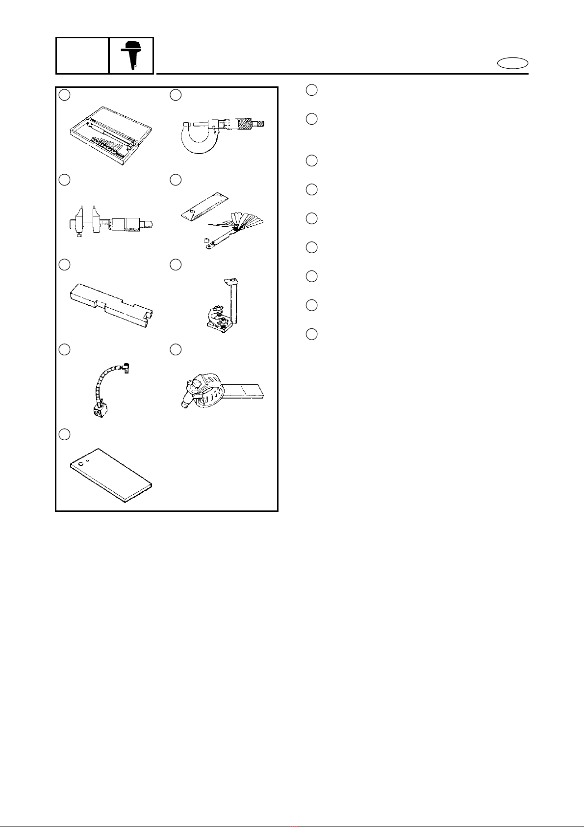
1. The right tools
Use the recommended special tools to
protect parts from damage. Use the
right tool in the right manner - do not
improvise.
2. Tightening torque
Follow the tightening torque instruc-
tions. When tightening bolts, nuts and
screws, tighten the large sizes first, and
tighten inner-positioned fixings before
outer-positioned ones.