Yamaha 15F User manual

OWNER’S MANUAL
9.9F
15F
63V-28199-78-E0
U63V78E0.book Page 1 Monday, March 6, 2006 10:05 AM

Read this owner’s manual carefully before operating your outboard motor.
U63V78E0.book Page 1 Monday, March 6, 2006 10:05 AM

Important manual information
EMU25101
To the owner
Thank you for choosing a Yamaha outboard
motor. This Owner’s Manual contains infor-
mation needed for proper operation, mainte-
nance and care. A thorough understanding of
these simple instructions will help you obtain
maximum enjoyment from your new Yamaha.
If you have any question about the operation
or maintenance of your outboard motor,
please consult a Yamaha dealer.
In this Owner’s Manual particularly important
information is distinguished in the following
ways.
The Safety Alert Symbol means AT-
TENTION! BECOME ALERT! YOUR SAFE-
TY IS INVOLVED!
WARNING
EWM00780
Failure to follow WARNING instructions
could result in severe injury or death to the
machine operator, a bystander, or a per-
son inspecting or repairing the outboard
motor.
CAUTION:
ECM00700
A CAUTION indicates special precautions
that must be taken to avoid damage to the
outboard motor.
NOTE:
A NOTE provides key information to make
procedures easier or clearer.
Yamaha continually seeks advancements in
product design and quality. Therefore, while
this manual contains the most current product
information available at the time of printing,
there may be minor discrepancies between
your machine and this manual. If there is any
question concerning this manual, please con-
sult your Yamaha dealer.
To ensure long product life, Yamaha recom-
mends that you use the product and perform
the specified periodic inspections and mainte-
nance by correctly following the instructions in
the owner’s manual. Note that if you do not
follow these instructions, not only may the
product break down, but the warranty will also
be voided.
Some countries have laws or regulations re-
stricting users from taking the product out of
the country where it was purchased, and it
may be impossible to register the product in
the destination country. Additionally, the war-
ranty may not apply in certain regions. When
planning to take the product to another coun-
try, consult the dealer where the product was
purchased for further information.
If the product was purchased used, please
consult your closest dealer for customer re-
registration, and to be eligible for the specified
services.
NOTE:
The 9.9FMH, 15FMH and the standard ac-
cessories are used as a base for the explana-
tions and illustrations in this manual.
Therefore some items may not apply to every
model.
U63V78E0.book Page 1 Monday, March 6, 2006 10:05 AM

Important manual information
EMU25120
9.9F, 15F
OWNER’S MANUAL
©2006 by Yamaha Motor Co., Ltd.
1st Edition, January 2006
All rights reserved.
Any reprinting or unauthorized use
without the written permission of
Yamaha Motor Co., Ltd.
is expressly prohibited.
Printed in Japan
U63V78E0.book Page 2 Monday, March 6, 2006 10:05 AM

Table of contents
General information .......................... 1
Identification numbers record.......... 1
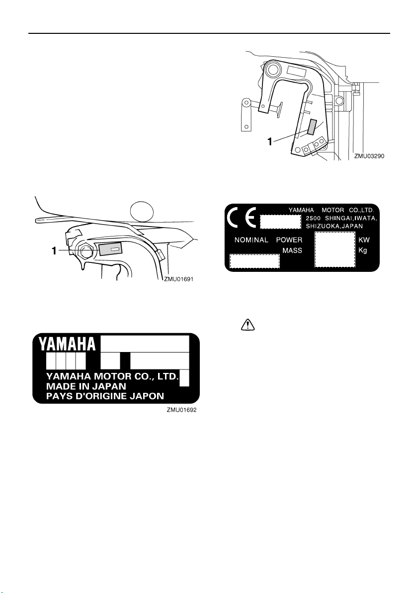
Outboard motor serial number ........... 1
EC label........................................... 1
Safety information ........................... 1
Important labels............................... 3
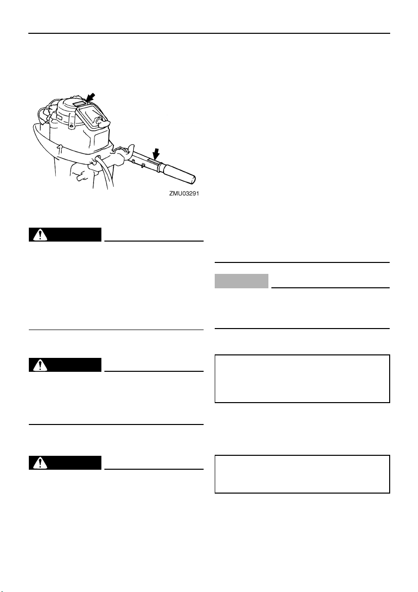
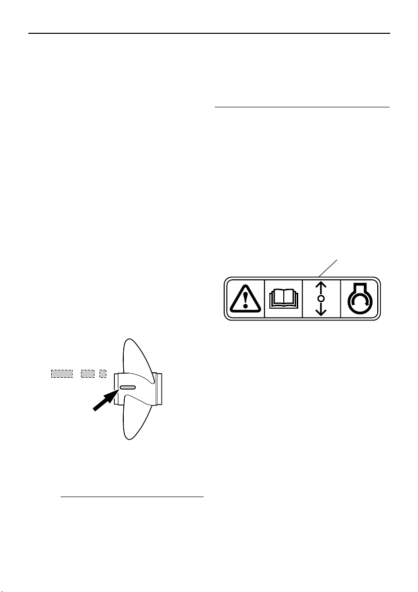
Warning labels.................................... 3
Fueling instructions ......................... 3
Gasoline ............................................. 3
Engine oil............................................ 3
Propeller selection........................... 4
Start-in-gear protection ................... 4
Basic components ............................5
Main components............................ 5
Fuel tank............................................. 5
Fuel joint............................................. 6
Fuel gauge ......................................... 6
Fuel tank cap...................................... 6
Air vent screw..................................... 6
Tiller handle........................................ 6
Gear shift lever................................... 6
Throttle grip ........................................ 6
Throttle indicator................................. 7
Throttle friction adjuster...................... 7
Engine stop lanyard switch................. 7
Engine stop button ............................. 8
Choke knob ........................................ 8
Manual starter handle......................... 8
Steering friction adjuster..................... 9
Trim rod (tilt pin) ................................. 9
Tilt lock mechanism............................ 9
Tilt support bar ................................... 9
Top cowling lock lever(s)
(turn type)........................................ 9
2-pin connector................................. 10
Operation ......................................... 11
Installation ..................................... 11
Mounting the outboard motor ........... 11
Clamping the outboard motor........... 12
Breaking in engine ........................ 13
Gasoline and engine oil mixing
chart (50:1).................................... 13
Procedure for pre-mixed models ...... 13
Preoperation checks ..................... 14
Fuel .................................................. 14
Oil ..................................................... 14
Controls ............................................ 14
Engine .............................................. 14
Filling fuel and engine oil .............. 14
Filling fuel for portable tank .............. 14
Gasoline and oil mixing (100:1)........ 14
Operating engine .......................... 15
Feeding fuel (portable tank) ............. 15
Starting engine ................................. 16
Warming up engine....................... 18
Choke start models .......................... 18
Shifting .......................................... 18
Forward (tiller handle and remote
control models) ............................. 19
Reverse (manual tilt and hydro tilt
models) ......................................... 19
Stopping engine ............................ 20
Procedure......................................... 20
Trimming outboard motor.............. 20
Adjusting trim angle for manual tilt
models .......................................... 21
Adjusting boat trim............................ 21
Tilting up and down....................... 22
Procedure for tilting up (manual tilt
models) ......................................... 23
Procedure for tilting down (manual
tilt models)..................................... 23
Cruising in shallow water .............. 24
Cruising in shallow water (manual
tilt models)..................................... 24
Cruising in other conditions........... 25
Maintenance .................................... 26
Specifications................................ 26
Transporting and storing outboard
motor.......................................... 27
Clamp screw mounting models ........ 27
U63V78E0.book Page 1 Monday, March 6, 2006 10:05 AM

Table of contents
Storing outboard motor..................... 27
Procedure......................................... 28
Lubrication (except oil injection
models) ......................................... 29
Cleaning the outboard motor............ 29
Checking painted surface of motor... 29
Periodic maintenance.................... 29
Replacement parts ........................... 29
Maintenance chart............................ 30
Greasing........................................... 31
Cleaning and adjusting spark plug ... 31
Checking fuel system ....................... 32
Inspecting fuel filter .......................... 33
Cleaning fuel filter............................. 33
Inspecting idling speed..................... 33
Checking wiring and connectors ...... 34
Exhaust leakage............................... 34
Water leakage .................................. 34
Checking propeller ........................... 34
Removing the propeller .................... 35
Installing the Propeller...................... 35
Changing gear oil ............................. 36
Cleaning fuel tank............................. 37
Inspecting and replacing anode(s) ... 37
Checking top cowling ....................... 38
Coating the boat bottom................... 38
Trouble Recovery ............................ 39
Troubleshooting ............................ 39
Temporary action in emergency.... 42
Impact damage................................. 42
Starter will not operate ..................... 42
Emergency starting engine............... 43
Treatment of submerged motor..... 44
Procedure......................................... 44
U63V78E0.book Page 2 Monday, March 6, 2006 10:05 AM

General information
1
EMU25170
Identification numbers record
EMU25183
Outboard motor serial number
The outboard motor serial number is stamped
on the label attached to the port side of the
clamp bracket.
Record your outboard motor serial number in
the spaces provided to assist you in ordering
spare parts from your Yamaha dealer or for
reference in case your outboard motor is sto-
len.
EMU25202
EC label
Engines affixed with this label conform to cer-
tain portions of the European Parliament di-
rective relating to machinery. Refer to the
label and the EC Declaration of Conformity for
more details.
EMU25371
Safety information
●Before mounting or operating the outboard
motor, read this entire manual. Reading it
should give you an understanding of the
motor and its operation.
●Before operating the boat, read any own-
er’s or operator’s manuals supplied with it
and all labels. Be sure you understand each
item before operating.
●Do not overpower the boat with this out-
board motor. Overpowering the boat could
result in loss of control. The rated power of
the outboard should be equal to or less than
the rated horsepower capacity of the boat.
If the rated horsepower capacity of the boat
is unknown, consult the dealer or boat man-
ufacturer.
1. Outboard motor serial number location
1. EC label location
ZMU01696
U63V78E0.book Page 1 Monday, March 6, 2006 10:05 AM

General information
2
●Do not modify the outboard. Modifications
could make the motor unfit or unsafe to use.
●Incorrect propeller selection and incorrect
use may not only cause engine damage,
but also adversely affect fuel consumption.
Consult your dealer for correct use.
●Never operate after drinking alcohol or tak-
ing drugs. About 50% of all boating fatalities
involve intoxication.
●Have an approved personal flotation device
(PFD) on board for every occupant. It is a
good idea to wear a PFD whenever boat-
ing. At a minimum, children and non-swim-
mers should always wear PFDs, and
everyone should wear PFDs when there
are potentially hazardous boating condi-
tions.
●Gasoline is highly flammable, and its va-
pors are flammable and explosive. Handle
and store gasoline carefully. Make sure
there are no gas fumes or leaking fuel be-
fore starting the engine.
●This product emits exhaust gases which
contain carbon monoxide, a colorless,
odorless gas which may cause brain dam-
age or death when inhaled. Symptoms in-
clude nausea, dizziness, and drowsiness.
Keep cockpit and cabin areas well ventilat-
ed. Avoid blocking exhaust outlets.
●Check throttle, shift, and steering for proper
operation before starting the engine.
●Attach the engine stop switch lanyard to a
secure place on your clothing, or your arm
or leg while operating. If you accidentally
leave the helm, the lanyard will pull from the
switch, stopping the engine.
●Know the marine laws and regulations
where you will be boating - and obey them.
●Stay informed about the weather. Check
weather forecasts before boating. Avoid
boating in hazardous weather.
●Tell someone where you are going: leave a
Float Plan with a responsible person. Be
sure to cancel the Float Plan when you re-
turn.
●Use common sense and good judgment
when boating. Know your abilities, and be
sure you understand how your boat han-
dles under the different boating conditions
you may encounter. Operate within your
limits, and the limits of your boat. Always
operate at safe speeds, and keep a careful
watch for obstacles and other traffic.
●Always watch carefully for swimmers during
the engine operation.
●Stay away from swimming areas.
●When a swimmer is in the water near you
shift into neutral and shut off the engine.
●Do not illegally discard empty containers
used to replace or replenish oil. For the cor-
rect processing of empty containers, con-
sult the dealer where you purchased the oil.
●When replacing oils used to lubricate the
product (engine or gear oil), be sure to wipe
away any spilt oil. Never pour oil without us-
ing a funnel or similar device. If necessary,
verify the necessary replacement proce-
dure with the dealer.
●Never illegally discard (dump) the product.
Yamaha recommends consulting the deal-
er on discarding the product.
U63V78E0.book Page 2 Monday, March 6, 2006 10:05 AM

General information
3
EMU25382
Important labels
EMU25395
Warning labels
EMU25401
Label
WARNING
EWM01260
●Be sure shift control is in neutral before
starting engine. (except 2HP)
●Do not touch or remove electrical parts
when starting or during operation.
●Keep hands, hair, and clothes away from
flywheel and other rotating parts while
engine is running.
EMU25431
Label
WARNING
EWM01300
●This engine is equipped with a neutral
starting device.
●The engine will not start unless the shift
control is in neutral position.
EMU25540
Fueling instructions
WARNING
EWM00010
GASOLINE AND ITS VAPORS ARE HIGH-
LY FLAMMABLE AND EXPLOSIVE!
●Do not smoke when refueling, and keep
away from sparks, flames, or other
sources of ignition.
●Stop engine before refueling.
●Refuel in a well-ventilated area. Refuel
portable fuel tanks off the boat.
●Take care not to spill gasoline. If gaso-
line spills, wipe it up immediately with
dry rags.
●Do not overfill the fuel tank.
●Tighten the filler cap securely after refu-
eling.
●If you should swallow some gasoline, in-
hale a lot of gasoline vapor, or get gaso-
line in your eyes, get immediate medical
attention.
●If any gasoline spills onto your skin, im-
mediately wash with soap and water.
Change clothing if gasoline spills on it.
●Touch the fuel nozzle to the filler open-
ing or funnel to help prevent electrostat-
ic sparks.
CAUTION:
ECM00010
Use only new clean gasoline which has
been stored in clean containers and is not
contaminated with water or foreign matter.
EMU25580
Gasoline
If knocking or pinging occurs, use a different
brand of gasoline or premium unleaded fuel.
EMU25650
Engine oil
If the recommended engine oil is not avail-
able, another 2-stroke engine oil with an
NMMA-certified TC-W3 rating may be used.
Recommended gasoline:
Regular unleaded gasoline with a mini-
mum octane rating of 90 (Research
Octane Number).
Recommended engine oil:
YAMALUBE 2-stroke outboard motor
oil
U63V78E0.book Page 3 Monday, March 6, 2006 10:05 AM

General information
4
EMU25742
Propeller selection
The performance of your outboard motor will
be critically affected by your choice of propel-
ler, as an incorrect choice could adversely af-
fect performance and could also seriously
damage the motor. Engine speed depends on
the propeller size and boat load. If engine
speed is too high or too low for good engine
performance, this will have an adverse effect
on the engine.
Yamaha outboard motors are fitted with pro-
pellers chosen to perform well over a range of
applications, but there may be uses where a
propeller with a different pitch would be more
appropriate. For a greater operating load, a
smaller-pitch propeller is more suitable as it
enables the correct engine speed to be main-
tained. Conversely, a larger-pitch propeller is
more suitable for a smaller operating load.
Yamaha dealers stock a range of propellers,
and can advise you and install a propeller on
your outboard that is best suited to your appli-
cation.
NOTE:
Select a propeller which will allow the engine
to reach the middle or upper half of the oper-
ating range at full throttle with the maximum
boat load. If operating conditions such as light
boat loads then allow the engine r/min to rise
above the maximum recommended range, re-
duce the throttle setting to maintain the en-
gine in the proper operating range.
For instructions on propeller removal and in-
stallation, see page 34.
EMU25760
Start-in-gear protection
Yamaha outboard motors affixed with the pic-
tured label or Yamaha-approved remote con-
trol units are equipped with start-in-gear
protection device(s). This feature permits the
engine to be started only when it is in neutral.
Always select neutral before starting the en-
gine.
1. Propeller diameter in inches
2. Propeller pitch in inches
3. Type of propeller (propeller mark)
ZMU04606
-
x
123
1. Start-in-gear protection label
ZMU01713
1
U63V78E0.book Page 4 Monday, March 6, 2006 10:05 AM

Basic components
5
EMU25797
Main components
NOTE:
* May not be exactly as shown; also may not be included as standard equipment on all models.
EMU25802
Fuel tank
If your model was equipped with a portable
fuel tank, its function is as follows.
WARNING
EWM00020
The fuel tank supplied with this engine is
its dedicated fuel reservoir and must not
be used as a fuel storage container. Com-
mercial users should conform to relevant
licensing or approval authority regula-
tions.
1. Top cowling
2. Top cowling lock lever
3. Cooling water pilot hole
4. Tilt lock lever
5. Manual starter handle
6. Gear shift lever
7. Engine stop button/Engine stop lanyard
switch
8. Throttle grip
9. Throttle friction adjuster
10.Clamp screw
11.2-pin connector
12.Choke knob
13.Rope attachment
14.Clamp bracket
15.Trim rod
16.Anti-cavitation plate
17.Cooling water inlet
18.Propeller*
19.Fuel tank
U63V78E0.book Page 5 Monday, March 6, 2006 10:05 AM

Basic components
6
EMU25830
Fuel joint
This joint is used to connect the fuel line.
EMU25841
Fuel gauge
This gauge is located on either the fuel tank
cap or on the fuel joint base. It shows the ap-
proximate amount of fuel remaining in the
tank.
EMU25850
Fuel tank cap
This cap seals the fuel tank. When removed,
the tank can be filled with fuel. To remove the
cap, turn it counterclockwise.
EMU25860
Air vent screw
This screw is on the fuel tank cap. To loosen
the screw, turn it counterclockwise.
EMU25911
Tiller handle
To change direction, move the tiller handle to
the left or right as necessary.
EMU25922
Gear shift lever
Pulling the gear shift lever towards you puts
the engine in forward gear so that the boat
moves ahead. Pushing the lever away from
you puts the engine in reverse gear so that the
boat moves astern.
EMU25941
Throttle grip
The throttle grip is on the tiller handle. Turn
the grip counterclockwise to increase speed
and clockwise to decrease speed.
1. Fuel joint
2. Fuel gauge
3. Fuel tank cap
4. Air vent screw
1. Forward “”
2. Neutral “”
3. Reverse “”
U63V78E0.book Page 6 Monday, March 6, 2006 10:05 AM

Basic components
7
EMU25961
Throttle indicator
The fuel consumption curve on the throttle in-
dicator shows the relative amount of fuel con-
sumed for each throttle position. Choose the
setting that offers the best performance and
fuel economy for the desired operation.
EMU25971
Throttle friction adjuster
A friction device provides adjustable resis-
tance to movement of the throttle grip or the
remote control lever, and can be set accord-
ing to operator preference.
To increase resistance, turn the adjuster
clockwise. To decrease resistance, turn the
adjuster counterclockwise.
WARNING
EWM00031
Do not overtighten the friction adjuster. If
there is too much resistance, it could be
difficult to move the remote control lever
or throttle grip, which could result in an
accident.
When constant speed is desired, tighten the
adjuster to maintain the desired throttle set-
ting.
EMU25990
Engine stop lanyard switch
The lock plate must be attached to the engine
stop switch for the engine to run. The lanyard
should be attached to a secure place on the
operator’s clothing, or arm or leg. Should the
operator fall overboard or leave the helm, the
lanyard will pull out the lock plate, stopping ig-
nition to the engine. This will prevent the boat
from running away under power.
WARNING
EWM00120
●Attach the engine stop switch lanyard to
a secure place on your clothing, or your
arm or leg while operating.
●Do not attach the lanyard to clothing
that could tear loose. Do not route the
lanyard where it could become entan-
gled, preventing it from functioning.
1. Throttle indicator
U63V78E0.book Page 7 Monday, March 6, 2006 10:05 AM

Basic components
8
●Avoid accidentally pulling the lanyard
during normal operation. Loss of engine
power means the loss of most steering
control. Also, without engine power, the
boat could slow rapidly. This could
cause people and objects in the boat to
be thrown forward.
NOTE:
The engine cannot be started with the lock
plate removed.
EMU26001
Engine stop button
To open the ignition circuit and stop the en-
gine, push this button.
EMU26030
Choke knob
To supply the engine with the rich fuel mixture
required to start, pull out this knob. The choke
knob has the 4 operating positions shown in
the following illustration.
EMU26070
Manual starter handle
To start the engine, first gently pull the handle
out until resistance is felt. From that position,
then pull the handle straight out quickly to
crank the engine.
1. Lanyard
2. Lock plate
1. Use to start a hot engine
2. Use to warm up a cold engine or restart a
warm engine
3. Use to warm up a cold engine or restart a
warm engine
4. Use to start a cold engine
U63V78E0.book Page 8 Monday, March 6, 2006 10:05 AM

Basic components
9
EMU26122
Steering friction adjuster
A friction device provides adjustable resis-
tance to the steering mechanism, and can be
set according to operator preference. An ad-
justing screw or bolt is located on the swivel
bracket.
To increase resistance, turn the adjuster
clockwise.
To decrease resistance, turn the adjuster
counterclockwise.
WARNING
EWM00040
Do not overtighten the friction adjuster. If
there is too much resistance, it could be
difficult to steer, which could result in an
accident.
EMU26261
Trim rod (tilt pin)
The position of the trim rod determines the
minimum trim angle of the outboard motor in
relation to the transom.
EMU30440
Tilt lock mechanism
The tilt lock mechanism is used to prevent the
outboard motor from lifting out of the water
when in reverse gear.
To tilt the outboard motor up, set the tilt lock
lever to the “”(up) position. To tilt the out-
board motor down, set the tilt lock lever to the
“”(down) position.
EMU26330
Tilt support bar
The tilt support bar keeps the outboard motor
in the tilted up position.
EMU26372
Top cowling lock lever(s) (turn type)
To remove the engine top cowling, turn the
lock lever(s) and lift off the cowling. When in-
stalling the cowling, check to be sure it fits
properly in the rubber seal. Then lock the
cowling again by returning the lever(s) to the
lock position.
1. Tilt lock lever
U63V78E0.book Page 9 Monday, March 6, 2006 10:05 AM

Basic components
10
EMU26410
2-pin connector
AC 12 V-40/60/80W power is delivered
through this connector. When using it, keep in
mind the following points:
●Use a genuine Yamaha connector.
●Use lighting equipment only.
●Connect lighting equipment directly to the
2-pin connector.
●Capacity of the lighting equipment must be
more than 12 V-40/60/80W; otherwise the
bulb could burn out.
●When the connector is not in use, place the
cap on it.
CAUTION:
ECM01000
Do not connect the 2-pin connector direct-
ly to the battery terminals. Otherwise the
electric system will be damaged.
1. Top cowling lock lever(s)
U63V78E0.book Page 10 Monday, March 6, 2006 10:05 AM

Operation
11
EMU26901
Installation
CAUTION:
ECM00110
Incorrect engine height or obstructions to
smooth water flow (such as the design or
condition of the boat, or accessories such
as transom ladders or depth finder trans-
ducers) can create airborne water spray
while the boat is cruising. Severe engine
damage may result if the motor is operat-
ed continuously in the presence of air-
borne water spray.
NOTE:
During water testing check the buoyancy of
the boat, at rest, with its maximum load.
Check that the static water level on the ex-
haust housing is low enough to prevent water
entry into the powerhead, when water rises
due to waves when the outboard is not run-
ning.
EMU26910
Mounting the outboard motor
WARNING
EWM00820
●Overpowering a boat could cause se-
vere instability. Do not install an out-
board motor with more horsepower than
the maximum rating on the capacity
plate of the boat. If the boat does not
have a capacity plate, consult the boat
manufacturer.
●The information presented in this sec-
tion is intended as reference only. It is
not possible to provide complete in-
structions for every possible boat and
motor combination. Proper mounting
depends in part on experience and the
specific boat and motor combination.
WARNING
EWM00830
Improper mounting of the outboard motor
could result in hazardous conditions such
as poor handling, loss of control, or fire
hazards. Observe the following:
●For permanently mounted models, your
dealer or other person experienced in
proper rigging should mount the motor.
If you are mounting the motor yourself,
you should be trained by an experienced
person.
●For portable models, your dealer or oth-
er person experienced in proper out-
board motor mounting should show you
how to mount your motor.
Mount the outboard motor on the center line
(keel line) of the boat, and ensure that the
boat itself is well balanced. Otherwise the
boat will be hard to steer. For boats without a
keel or which are asymmetrical, consult your
dealer.
EMU26920
Mounting height
To run your boat at optimum efficiency, the
water resistance (drag) of the boat and out-
board motor must be made as little as possi-
ble. The mounting height of the outboard
motor greatly affects the water resistance. If
the mounting height is too high, cavitation
1. Center line (keel line)
ZMU01760
1
U63V78E0.book Page 11 Monday, March 6, 2006 10:05 AM

Operation
12
tends to occur, thus reducing the propulsion;
and if the propeller tips cut the air, the engine
speed will rise abnormally and cause the en-
gine to overheat. If the mounting height is too
low, the water resistance will increase and
thereby reduce engine efficiency. Mount the
outboard motor so that the anti-cavitation
plate is between the bottom of the boat and a
level 25 mm (1 in.) below it.
NOTE:
●The optimum mounting height of the out-
board motor is affected by the boat and mo-
tor combination and the desired use. Test
runs at different heights can help determine
the optimum mounting height. Consult your
Yamaha dealer or boat manufacturer for
further information on determining the prop-
er mounting height.
●For instructions on setting the trim angle of
the outboard motor, see page 20.
EMU26970
Clamping the outboard motor
1. Place the outboard motor on the transom
so that it is positioned as close to the cen-
ter as possible. Tighten the transom
clamp screws evenly and securely. Oc-
casionally check the clamp screws for
tightness during operation of the out-
board motor because they could become
loose due to engine vibration.
WARNING
EWM00640
Loose clamp screws could allow the out-
board motor to fall off or move on the tran-
som. This could cause loss of control and
serious injury. Make sure the transom
screws are tightened securely. Occasion-
ally check the screws for tightness during
operation.
2. If the engine restraint cable attachment is
equipped on your engine, an engine re-
straint cable or chain should be used. At-
tach one end to the engine restraint cable
attachment and the other to a secure
mounting point on the boat. Otherwise
the engine could be completely lost if it
accidentally falls off the transom.
ZMU02011
0–25mm
(0–1in.)
ZMU02012
ZMU02013
U63V78E0.book Page 12 Monday, March 6, 2006 10:05 AM

Operation
13
3. Secure the clamp bracket to the transom
using the bolts provided with the out-
board (if packed). For details, consult
your Yamaha dealer.
WARNING
EWM00650
Avoid using bolts, nuts or washers other
than those contained in the engine pack-
aging. If used, they must be of at least the
same quality of material and strength and
must be tightened securely. After tighten-
ing, test run the engine and check their
tightness.
EMU30173
Breaking in engine
Your new engine requires a period of break-in
to allow mating surfaces of moving parts to
wear in evenly. Correct break-in will help en-
sure proper performance and longer engine
life.
CAUTION:
ECM00800
Failure to follow the break-in procedure
could result in reduced engine life or even
severe engine damage.
EMU27060
Gasoline and engine oil mixing chart
(50:1)
CAUTION:
ECM00150
Be sure to mix gasoline and oil complete-
ly, otherwise the engine may be damaged.
EMU27074
Procedure for pre-mixed models
Run the engine under load (in gear with a pro-
peller installed) for 10 hours as follows.
1. First 10 minutes:
Run the engine at the lowest possible
speed. A fast idle in neutral is best.
2. Next 50 minutes:
Do not exceed half throttle (approximate-
ly 3000 r/min). Vary engine speed occa-
sionally. If you have an easy-planing
boat, accelerate at full throttle onto plane,
then immediately reduce the throttle to
3000 r/min or less.
3. Next two hours:
Accelerate at full throttle onto plane, then
reduce engine speed to three-quarter
throttle (approximately 4000 r/min). Vary
engine speed occasionally. Run at full
throttle for one minute, then allow about
10 minutes of operation at three-quarter
throttle or less to let the engine cool.
4. Remaining seven hours:
Run the engine at any speed. However,
avoid operating at full throttle for more
than 5 minutes at a time.
5. After the first 10 hours:
Operate the engine normally. Use the
standard premix ratio of gasoline and oil.
For details on mixing fuel and oil, see
page 14.
1. : Gasoline
2. : Engine oil
U63V78E0.book Page 13 Monday, March 6, 2006 10:05 AM

Operation
14
EMU27102
Preoperation checks
WARNING
EWM00080
If any item in the preoperation check is not
working properly, have it inspected and
repaired before operating the outboard
motor. Otherwise an accident could occur.
CAUTION:
ECM00120
Do not start the engine out of water. Over-
heating and serious engine damage can
occur.
EMU27111
Fuel
●Check to be sure you have plenty of fuel for
your trip.
●Make sure there are no fuel leaks or gaso-
line fumes.
●Check fuel line connections to be sure they
are tight (if equipped Yamaha fuel tank or
boat tank).
●Be sure the fuel tank is positioned on a se-
cure, flat surface, and that the fuel line is not
twisted or flattened, or likely to contact
sharp objects (if equipped Yamaha fuel
tank or boat tank).
EMU27120
Oil
●Check to be sure you have plenty of oil for
your trip.
EMU27130
Controls
●Check throttle, shift, and steering for proper
operation before starting the engine.
●The controls should work smoothly, without
binding or unusual free play.
●Look for loose or damaged connections.
●Check operation of the starter and stop
switches when the outboard motor is in the
water.
EMU27140
Engine
●Check the engine and engine mounting.
●Look for loose or damaged fasteners.
●Check the propeller for damage.
EMU27233
Filling fuel and engine oil
EMU27242
Filling fuel for portable tank
WARNING
EWM00060
Gasoline and its vapors are highly flam-
mable and explosive. Keep away from
sparks, cigarettes, flames, or other sourc-
es of ignition.
1. Remove the fuel tank cap.
2. Fill the fuel tank carefully.
3. Close the cap securely after refueling.
Wipe up any spilled fuel.
EMU27404
Gasoline and oil mixing (100:1)
Fuel tank capacity (if equipped Yamaha
fuel tank):
25.0 L (6.61 US gal) (5.50 Imp.gal)
Gasoline to engine oil
ratio
Break-in period See page 13
After break-in 100:1
1. : Gasoline
2. : Engine oil
100:1
1 L
(0.26 US gal,
0.22 Imp gal)
12 L
(3.2 US gal,
2.6 Imp gal)
14 L
(3.7 US gal,
3.1 Imp gal)
24 L
(6.3 US gal,
5.3 Imp gal)
0.01 L
(0.01 US qt,
0.01 Imp qt)
0.12 L
(0.13 US qt,
0.11 Imp qt)
0.14 L
(0.15 US qt,
0.12 Imp qt)
0.24 L
(0.25 US qt,
0.21 Imp qt)
ZMU04910
U63V78E0.book Page 14 Monday, March 6, 2006 10:05 AM
Other manuals for 15F
2
This manual suits for next models
1
Table of contents
Other Yamaha Outboard Motor manuals
Popular Outboard Motor manuals by other brands

SLEIPNER MOTOR AS
SLEIPNER MOTOR AS Side-Power SE-20/110 S installation manual

SLEIPNER MOTOR AS
SLEIPNER MOTOR AS Side-Power SH 700/ 412 TC Installation and user manual

Mercury
Mercury V6 175 Diagnostic manual

Mercury
Mercury 40 jet fourstroke manual

TOHATSU
TOHATSU MFS 30B owner's manual

Volvo Penta
Volvo Penta VP 140 Workshop manual