0-4
0
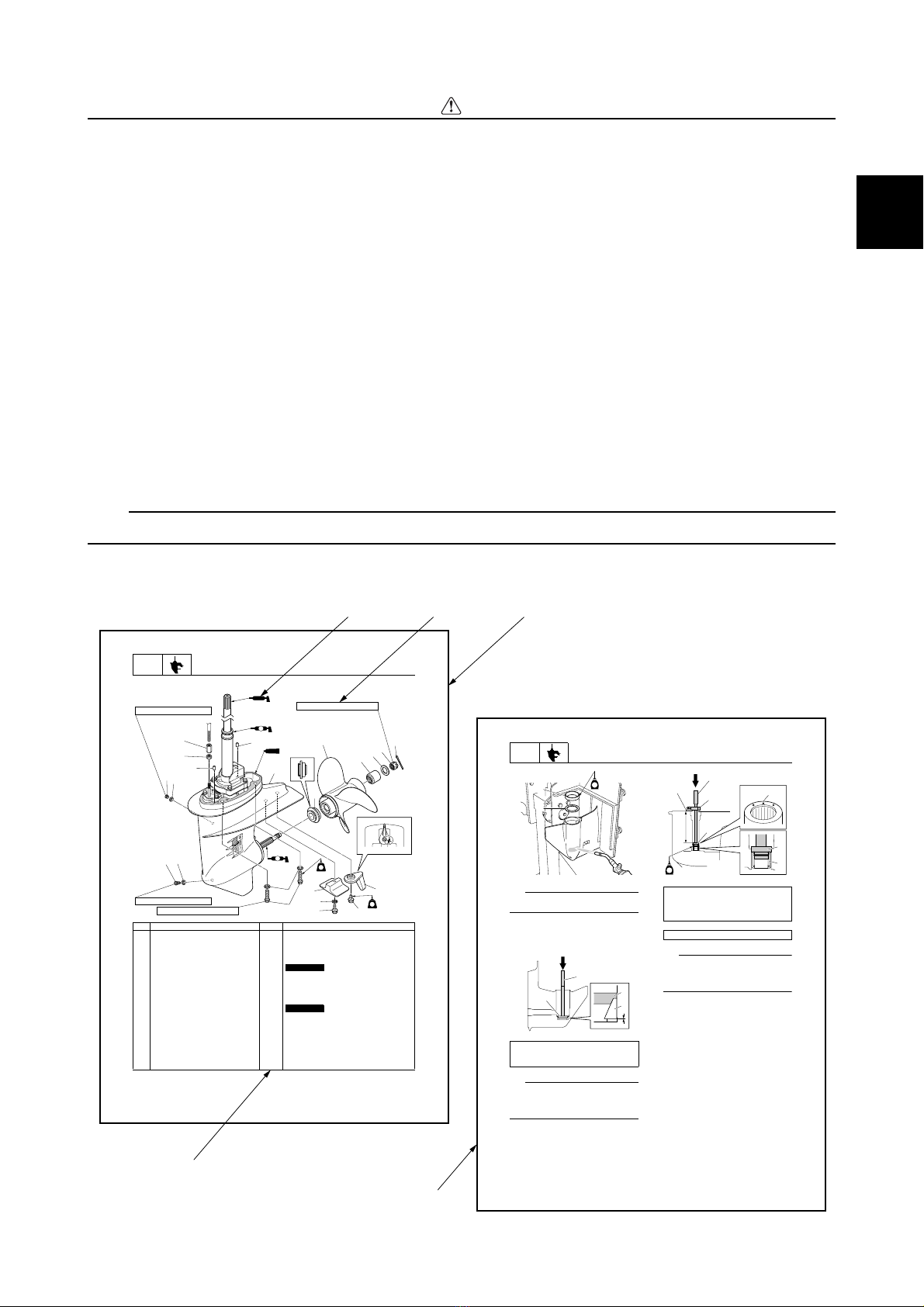
How to use this manual
Manual format
The format of this manual has been designed to make service procedures clear and easy to under-
stand. Use the following information as a guide for effective and quality service.
•Parts are shown and detailed in an exploded diagram and are listed in the component list (see 1
in the following figure for an example page).
•The component list consists of part names and quantities, as well as bolt and screw dimensions
(see 2in the following figure).
•Symbols are used to indicate important aspects of a procedure, such as the grade of lubricant and
the lubrication points (see 3in the following figure).
•Tightening torque specifications are provided in the exploded diagrams (see 4in the following fig-
ure), and in the related detailed instructions. Some torque specifications are listed in stages as
torque figures or angles in degrees.
•Separate procedures and illustrations are used to explain the details of removal, checking, and
installation where necessary (see 5in the following figure for an example page).
TIP:
For troubleshooting procedures, see Chapter 4, “Troubleshooting.”
LOWR Lower unit
8-1
Lower unit
No. Part name Q’ty Remarks
1tungnitsujdA1
1tunkcoL2
2lewoD3
1wercskcehC4
2teksaG5 Not reusable
1wercsniarD6
4rehsaW7
01M4tloB8 ×35 mm
1edonA9
1rehsawlaicepS01 Not reusable
6M1tloB11 ×35 mm
6M1tloB21 ×18 mm
1batmirT31
1tinurewoL41
1recapS51
1relleporP61
1ralloC71
3
1
2
3
65
5
4
20
19
18
17
15
16
14
13
12
11
10
9
8
7
518
M
A
D
LT
572
LT
LT
572
LT
1901
9 N ·m (0.9 kgf ·m, 6.6 ft ·Ib)
9 N ·m (0.9 kgf ·m, 6.6 ft ·Ib) 34 N ·m (3.4 kgf ·m, 25.1 ft ·Ib)
37 N ·m (3.7 kgf ·m, 27.3 ft ·Ib)
LOWR Lower unit
8-17
TIP:
Do not reuse a shim if deformed or
scratched.
3. While holding the special service tool 3,
strike the tool to check that the taper
roller bearing outer race is installed prop-
erly.
TIP:
If a high-pitched metallic sound is produced
when the special service tool is struck, the
taper roller bearing outer race 2is installed
properly.
4. Install a new needle bearing 5to the
specified depth a.
TIP:
• Face the identification mark bon the nee-
dle bearing toward the water pump side.
• Install the stopper conto the driver rod 6
at the specified depth a.
5. Heat the installation area of the taper
roller bearing outer race in the lower
case using a gas torch, and then install
the sleeve 9, the original pinion shims
0, and a new taper roller bearing outer
race A.
NOTICE:
When heating the
lower case, heat the entire installation
area evenly. Otherwise, the paint on
the lower case could be burned.
Driver rod LL 3: 90890-06605
Bearing outer race attachment 4:
90890-06625
1
2G
3
2
1
3
Driver rod SL 6: 90890-06602
Bearing depth plate 7: 90890-06603
Needle bearing attachment 8:
90890-06615
Depth a: 185.0–186.0 mm (7.28–7.32 in)
a
c
5
7
6
G
b
4
7
2
5
34 1
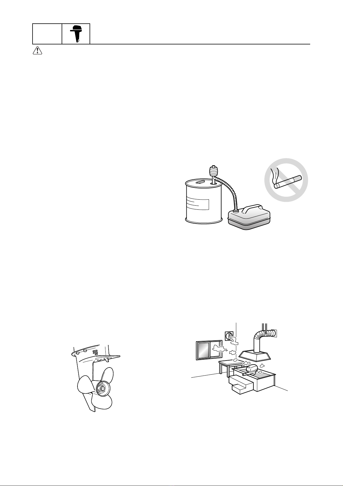
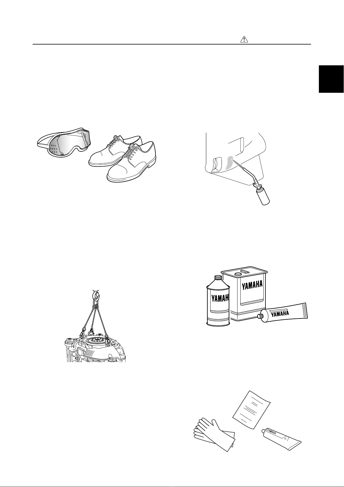
Safety while working / How to use this manual