Yamaha F20A User manual

OWNER’S MANUAL
F20A
F25A
FT25B
65W-28199-7B-E0

EMU25050
Read this owner’s manual carefully before operating your outboard motor.

Important manual information
EMU25101
To the owner
Thank you for choosing a Yamaha outboard
motor. This Owner’s Manual contains infor-
mation needed for proper operation, mainte-
nance and care. A thorough understanding
of these simple instructions will help you ob-
tain maximum enjoyment from your new
Yamaha. If you have any question about the
operation or maintenance of your outboard
motor, please consult a Yamaha dealer.
In this Owner’s Manual particularly important
information is distinguished in the following
ways.
The Safety Alert Symbol means
ATTENTION! BECOME ALERT! YOUR
SAFETY IS INVOLVED!
WARNING
EWM00780
Failure to follow WARNING instructions
could result in severe injury or death to
the machine operator, a bystander, or a
person inspecting or repairing the out-
board motor.
CAUTION:
ECM00700
A CAUTION indicates special precautions
that must be taken to avoid damage to the
outboard motor.
NOTE:
A NOTE provides key information to make
procedures easier or clearer.
Yamaha continually seeks advancements in
product design and quality. Therefore, while
this manual contains the most current prod-
uct information available at the time of print-
ing, there may be minor discrepancies
between your machine and this manual. If
there is any question concerning this manu-
al, please consult your Yamaha dealer.
To ensure long product life, Yamaha recom-
mends that you use the product and perform
the specified periodic inspections and main-
tenance by correctly following the instruc-
tions in the owner’s manual. Note that if you
do not follow these instructions, not only may
the product break down, but the warranty will
also be voided.
Some countries have laws or regulations re-
stricting users from taking the product out of
the country where it was purchased, and it
may be impossible to register the product in
the destination country. Additionally, the
warranty may not apply in certain regions.
When planning to take the product to another
country, consult the dealer where the prod-
uct was purchased for further information.
If the product was purchased used, please
consult your closest dealer for customer re-
registration, and to be eligible for the speci-
fied services.
NOTE:
The F20AE, F20AET, F25AMH, F25AE,
F25AET, FT25BET and the standard acces-
sories are used as a base for the explana-
tions and illustrations in this manual.
Therefore some items may not apply to ev-
ery model.

Important manual information
EMU25120
F20A, F25A, FT25B
OWNER’S MANUAL
©2005 by Yamaha Motor Co., Ltd.
1st Edition, February 2005
All rights reserved.
Any reprinting or unauthorized use
without the written permission of
Yamaha Motor Co., Ltd.
is expressly prohibited.
Printed in Japan

Table of contents
General information .......................... 1
Identification numbers record.......... 1
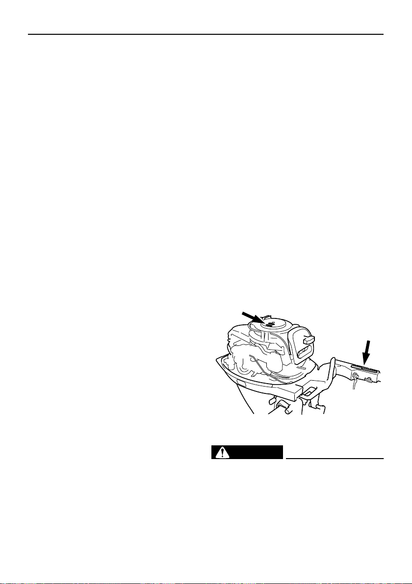
Outboard motor serial number .......... 1
Key number....................................... 1
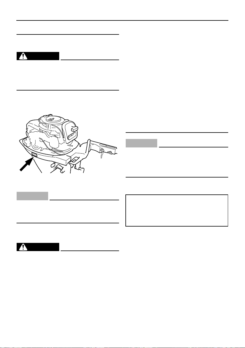
EC label........................................... 1
Emission control information ........... 2
SAV models ...................................... 2
Safety information ........................... 2
Important labels............................... 3
Warning labels .................................. 3
Caution labels ................................... 4
Fueling instructions ......................... 4
Gasoline............................................ 4
Engine oil .......................................... 5
Battery requirement......................... 5
Battery specifications ........................ 6
Without a rectifier or Rectifier
Regulator ........................................ 6
Propeller selection........................... 6
Start-in-gear protection ................... 7
Basic components ............................ 8
Main components............................ 8
Fuel tank ........................................... 9
Fuel joint ........................................... 9
Fuel gauge ........................................ 9
Fuel tank cap .................................... 9
Air vent screw ................................... 9
Remote control.................................. 9
Remote control lever....................... 10
Neutral interlock trigger................... 10
Neutral throttle lever........................ 10
Tiller handle .................................... 11
Gear shift lever................................ 11
Throttle grip..................................... 11
Throttle indicator ............................. 11
Throttle friction adjuster................... 12
Engine stop lanyard switch ............. 12
Engine stop button .......................... 13
Manual starter handle ..................... 13
Main switch ..................................... 13
Steering friction adjuster ................. 14
Power trim and tilt switch on
remote control or tiller handle ....... 14
Power trim and tilt switch on
bottom engine cowling .................. 14
Trim tab with anode.........................15
Trim tab ........................................... 15
Trim rod (tilt pin) .............................. 16
Tilt lock mechanism.........................16
Tilt support knob..............................16
Tilt support bar ................................ 16
Top cowling lock lever(s)
(turn type)...................................... 17
Flushing device ............................... 17
Warning indicator ............................ 17
Warning system ............................ 17
Overheat warning ............................ 17
Low oil pressure warning ................18
Operation ......................................... 19
Installation..................................... 19
Mounting the outboard motor .......... 19
Clamping the outboard motor..........20
Breaking in engine ........................ 21
Procedure for 4-stroke models........ 21
Preoperation checks ..................... 21
Fuel ................................................. 21
Controls ........................................... 21
Engine ............................................. 22
Checking the engine oil level ..........22
Filling fuel...................................... 22
Operating engine .......................... 23
Feeding fuel (portable tank) ............ 23
Starting engine ................................ 24
Warming up engine....................... 26
Manual start and electric start
models .......................................... 26
Shifting.......................................... 27
Forward (tiller handle and remote
control models) ............................. 27
Reverse (automatic reverse lock
and power trim and tilt models).....27
Reverse (manual tilt and hydro
tilt models)..................................... 28
Stopping engine............................ 29
Procedure........................................ 29
Trimming outboard motor.............. 30
Adjusting trim angle for manual
tilt models...................................... 30
Adjusting trim angle.........................31
Adjusting boat trim ..........................32

Table of contents
Tilting up and down ....................... 33
Procedure for tilting up (manual
tilt models) .................................... 33
Procedure for tilting up.................... 34
Procedure for tilting down
(manual tilt models) ...................... 35
Procedure for tilting down ............... 35
Cruising in shallow water .............. 36
Cruising in shallow water
(manual tilt models) ...................... 36
Power trim and tilt models /
power tilt models........................... 37
Cruising in other conditions........... 38
Maintenance..................................... 39
Specifications ................................ 39
Transporting and storing
outboard motor............................ 41
Clamp screw mounting models....... 42
Storing outboard motor ................... 42
Procedure ....................................... 43
Lubrication (except oil injection
models) ......................................... 44
Battery care..................................... 44
Flushing power unit......................... 44
Cleaning the outboard motor .......... 45
Checking painted surface
of motor......................................... 45
Periodic maintenance.................... 46
Replacement parts.......................... 46
Maintenance chart .......................... 47
Maintenance chart (additional)........ 48
Greasing ......................................... 49
Cleaning and adjusting
spark plug ..................................... 50
Checking fuel system...................... 51
Inspecting fuel filter ......................... 52
Cleaning fuel filter ........................... 52
Inspecting idling speed ................... 52
Changing engine oil ........................ 53
Checking wiring and connectors ..... 55
Exhaust leakage ............................. 55
Water leakage................................. 55
Engine oil leakage........................... 55
Checking power trim and tilt /
power tilt system ........................... 55
Checking propeller .......................... 56
Removing the propeller ................... 57
Installing the Propeller.....................57
Changing gear oil ............................ 58
Cleaning fuel tank ...........................59
Inspecting and replacing
anode(s)........................................ 60
Checking battery (for electric
start models) ................................. 60
Connecting the battery .................... 61
Disconnecting the battery................62
Checking top cowling ...................... 62
Coating the boat bottom.................. 62
Trouble Recovery............................ 63
Troubleshooting ............................ 63
Temporary action in emergency ... 66
Impact damage ............................... 66
Replacing fuse ................................ 66
Power trim and tilt / power tilt
will not operate..............................67
Starter will not operate .................... 67
Emergency starting engine .............68
Treatment of submerged motor .... 69
Procedure........................................ 69

1
General information
EMU25170
Identification numbers record
EMU25182
Outboard motor serial number
The outboard motor serial number is
stamped on the label attached to the port
side of the clamp bracket or the upper part of
the swivel bracket.
Record your outboard motor serial number in
the spaces provided to assist you in ordering
spare parts from your Yamaha dealer or for
reference in case your outboard motor is sto-
len.
EMU25190
Key number
If a main key switch is equipped with the mo-
tor, the key identification number is stamped
on your key as shown in the illustration.
Record this number in the space provided for
reference in case you need a new key.
EMU25202
EC label
Engines affixed with this label conform to
certain portions of the European Parliament
directive relating to machinery. Refer to the
label and the EC Declaration of Conformity
for more details.
1. Outboard motor serial number location
1
ZMU02638
1. Key number
1. EC label location
ZMU04946
1

General information
2
EMU25221
Emission control information
EMU25351
SAV models
Engines affixed with the label pictured below
conform to SAV (the Swiss exhaust emission
regulations for Swiss inshore waters).
Approval label of emission control certif-
icate
Fuel requirement label
EMU25371
Safety information
●
Before mounting or operating the outboard
motor, read this entire manual. Reading it
should give you an understanding of the
motor and its operation.
●
Before operating the boat, read any own-
er’s or operator’s manuals supplied with it
and all labels. Be sure you understand
each item before operating.
●
Do not overpower the boat with this out-
board motor. Overpowering the boat could
result in loss of control. The rated power of
the outboard should be equal to or less
than the rated horsepower capacity of the
boat. If the rated horsepower capacity of
the boat is unknown, consult the dealer or
boat manufacturer.
●
Do not modify the outboard. Modifications
could make the motor unfit or unsafe to
use.
●
Incorrect propeller selection and incorrect
use may not only cause engine damage,
but also adversely affect fuel consumption.
Consult your dealer for correct use.
●
Never operate after drinking alcohol or tak-
ing drugs. About 50% of all boating fatali-
ties involve intoxication.
●
Have an approved personal flotation de-
vice (PFD) on board for every occupant. It
is a good idea to wear a PFD whenever
boating. At a minimum, children and non-
1. Approval label location
ZMU01696
1
ZMU04967
YAMAHA MOTOR CO.,LTD.
Motorfamilie
Abgastypenpruf-
Nummer
ZMU04492
ZMU04494

General information
3
swimmers should always wear PFDs, and
everyone should wear PFDs when there
are potentially hazardous boating condi-
tions.
●
Gasoline is highly flammable, and its va-
pors are flammable and explosive. Handle
and store gasoline carefully. Make sure
there are no gas fumes or leaking fuel be-
fore starting the engine.
●
This product emits exhaust gases which
contain carbon monoxide, a colorless,
odorless gas which may cause brain dam-
age or death when inhaled. Symptoms in-
clude nausea, dizziness, and drowsiness.
Keep cockpit and cabin areas well ventilat-
ed. Avoid blocking exhaust outlets.
●
Check throttle, shift, and steering for prop-
er operation before starting the engine.
●
Attach the engine stop switch lanyard to a
secure place on your clothing, or your arm
or leg while operating. If you accidentally
leave the helm, the lanyard will pull from
the switch, stopping the engine.
●
Know the marine laws and regulations
where you will be boating - and obey them.
●
Stay informed about the weather. Check
weather forecasts before boating. Avoid
boating in hazardous weather.
●
Tell someone where you are going: leave
a Float Plan with a responsible person. Be
sure to cancel the Float Plan when you re-
turn.
●
Use common sense and good judgment
when boating. Know your abilities, and be
sure you understand how your boat han-
dles under the different boating conditions
you may encounter. Operate within your
limits, and the limits of your boat. Always
operate at safe speeds, and keep a careful
watch for obstacles and other traffic.
●
Always watch carefully for swimmers dur-
ing the engine operation.
●
Stay away from swimming areas.
●
When a swimmer is in the water near you
shift into neutral and shut off the engine.
●
Do not illegally discard empty containers
used to replace or replenish oil. For the
correct processing of empty containers,
consult the dealer where you purchased
the oil.
●
When replacing oils used to lubricate the
product (engine or gear oil), be sure to
wipe away any spilt oil. Never pour oil with-
out using a funnel or similar device. If nec-
essary, verify the necessary replacement
procedure with the dealer.
●
Never illegally discard (dump) the product.
Yamaha recommends consulting the deal-
er on discarding the product.
EMU25382
Important labels
EMU25395
Warning labels
EMU25401
Label
WARNING
EWM01260
●
Be sure shift control is in neutral before
starting engine. (except 2HP)
●
Do not touch or remove electrical parts
when starting or during operation.
●
Keep hands, hair, and clothes away
from flywheel and other rotating parts
ZMU02639

General information
4
while engine is running.
EMU25431
Label
WARNING
EWM01300
●
This engine is equipped with a neutral
starting device.
●
The engine will not start unless the shift
control is in neutral position.
EMU25465
Caution labels
EMU25472
Label
CAUTION:
ECM01190
Transport and store the engine only as
shown. Otherwise, engine damage could
result from Leaking oil.
EMU25540
Fueling instructions
WARNING
EWM00010
GASOLINE AND ITS VAPORS ARE HIGH-
LY FLAMMABLE AND EXPLOSIVE!
●
Do not smoke when refueling, and keep
away from sparks, flames, or other
sources of ignition.
●
Stop engine before refueling.
●
Refuel in a well-ventilated area. Refuel
portable fuel tanks off the boat.
●
Take care not to spill gasoline. If gaso-
line spills, wipe it up immediately with
dry rags.
●
Do not overfill the fuel tank.
●
Tighten the filler cap securely after re-
fueling.
●
If you should swallow some gasoline,
inhale a lot of gasoline vapor, or get
gasoline in your eyes, get immediate
medical attention.
●
If any gasoline spills onto your skin, im-
mediately wash with soap and water.
Change clothing if gasoline spills on it.
●
Touch the fuel nozzle to the filler open-
ing or funnel to help prevent electro-
static sparks.
CAUTION:
ECM00010
Use only new clean gasoline which has
been stored in clean containers and is not
contaminated with water or foreign mat-
ter.
EMU25580
Gasoline
If knocking or pinging occurs, use a different
brand of gasoline or premium unleaded fuel.
ZMU02640
Recommended gasoline:
Regular unleaded gasoline with a min-
imum octane rating of 90 (Research
Octane Number).

General information
5
EMU25683
Engine oil
NOTE:
If the recommended engine oil grades are
not available, select an alternative from the
following chart according to the average
temperatures in your area.
CAUTION:
ECM01050
All 4-stroke engines are shipped from the
factory without engine oil.
EMU25690
Battery requirement
CAUTION:
ECM01060
Do not use a battery that does not meet
the specified capacity. If a battery which
does not meet specifications is used, the
electric system could perform poorly or
be overloaded, causing electric system
damage.
For electric start models, choose a battery
Recommended engine oil:
4-stroke motor oil with a combination
of the following SAE and API oil classi-
fications
Engine oil type SAE:
10W-30 or 10W-40
Engine oil grade API:
SE, SF, SG, SH, SJ, SL
Engine oil quantity (excluding oil filter):
F20AE 1.7 L (1.80 US qt) (1.50 Imp.qt)
F20AET 1.7 L (1.80 US qt) (1.50
Imp.qt)
F25AE 1.7 L (1.80 US qt) (1.50 Imp.qt)
F25AET 1.7 L (1.80 US qt) (1.50
Imp.qt)
F25AMH 1.7 L (1.80 US qt) (1.50
Imp.qt)
FT25BET 1.9 L (2.01 US qt) (1.67
Imp.qt)
ZMU01710

General information
6
which meets the following specifications.
EMU25720
Battery specifications
EMU25730
Without a rectifier or Rectifier
Regulator
CAUTION:
ECM01090
A battery cannot be connected to models
that do not have a rectifier or Rectifier
Regulator.
If you wish to use a battery with the models
without a rectifier or Rectifier Regulator, in-
stall an optional Rectifier Regulator.
Using a maintenance-free battery with the
above models can shorten the life of the bat-
tery significantly.
Install an optional Rectifier Regulator or use
accessories rated to withstand 18 volts or
higher with the above models. Consult your
Yamaha dealer for details on installing an
optional Rectifier Regulator.
EMU25742
Propeller selection
The performance of your outboard motor will
be critically affected by your choice of propel-
ler, as an incorrect choice could adversely
affect performance and could also seriously
damage the motor. Engine speed depends
on the propeller size and boat load. If engine
speed is too high or too low for good engine
performance, this will have an adverse effect
on the engine.
Yamaha outboard motors are fitted with pro-
pellers chosen to perform well over a range
of applications, but there may be uses where
a propeller with a different pitch would be
more appropriate. For a greater operating
load, a smaller-pitch propeller is more suit-
able as it enables the correct engine speed
to be maintained. Conversely, a larger-pitch
propeller is more suitable for a smaller oper-
ating load.
Yamaha dealers stock a range of propellers,
and can advise you and install a propeller on
your outboard that is best suited to your ap-
plication.
Minimum cold cranking amps (CCA/EN):
F20AE 347.0 A
F20AET 347.0 A
F25AE 347.0 A
F25AET 347.0 A
FT25BET 347.0 A
Minimum rated capacity (20HR/IEC):
F20AE 40.0 Ah
F20AET 40.0 Ah
F25AE 40.0 Ah
F25AET 40.0 Ah
FT25BET 40.0 Ah
1. Propeller diameter in inches
2. Propeller pitch in inches
3. Type of propeller (propeller mark)
ZMU04604
-
x
123

General information
7
NOTE:
Select a propeller which will allow the engine
to reach the middle or upper half of the oper-
ating range at full throttle with the maximum
boat load. If operating conditions such as
light boat loads then allow the engine r/min to
rise above the maximum recommended
range, reduce the throttle setting to maintain
the engine in the proper operating range.
For instructions on propeller removal and in-
stallation, see page 56.
EMU25760
Start-in-gear protection
Yamaha outboard motors affixed with the
pictured label or Yamaha-approved remote
control units are equipped with start-in-gear
protection device(s). This feature permits the
engine to be started only when it is in neutral.
Always select neutral before starting the en-
gine.
1. Propeller diameter in inches
2. Propeller pitch in inches
3. Type of propeller (propeller mark)
ZMU04605
-
x
123
1. Start-in-gear protection label
ZMU01713
1

8
Basic components
EMU25796
Main components
NOTE:
* May not be exactly as shown; also may not be included as standard equipment on all mod-
els.
F20A, F25A, FT25B
EMU25802
Fuel tank
If your model was equipped with a portable
22
1
3
4
5
6
10
9
11
8
7
23
12
13 14 17
20
18
19
21
24
2
15 16
ZMU04968
1. Top cowling
2. Cooling water pilot hole
3. Top cowling lock lever(s)
4. Drain screw
5. Anti-cavitation plate
6. Trim tab (anode)
7. Propeller
8. Cooling water inlet
9. Trim rod*
10. Clamp bracket
11. Power trim and tilt switch*
12. Manual starter handle*
13. Warning indicator
14. Gear shift lever*
15. Engine stop button/Engine stop lanyard
switch*
16. Throttle friction adjuster*
17. Tiller handle*
18. Transom clamp handle*
19. Rope attachment
20. Tilt lock lever*
21. Flushing device*
22. Tilt support knob*
23. Fuel tank*
24. Remote control box (side mount type)*

Basic components
9
fuel tank, its function is as follows.
WARNING
EWM00020
The fuel tank supplied with this engine is
its dedicated fuel reservoir and must not
be used as a fuel storage container. Com-
mercial users should conform to relevant
licensing or approval authority regula-
tions.
EMU25830
Fuel joint
This joint is used to connect the fuel line.
EMU25841
Fuel gauge
This gauge is located on either the fuel tank
cap or on the fuel joint base. It shows the ap-
proximate amount of fuel remaining in the
tank.
EMU25850
Fuel tank cap
This cap seals the fuel tank. When removed,
the tank can be filled with fuel. To remove the
cap, turn it counterclockwise.
EMU25860
Air vent screw
This screw is on the fuel tank cap. To loosen
the screw, turn it counterclockwise.
EMU26180
Remote control
The remote control lever actuates both the
shifter and the throttle. The electrical switch-
es are mounted on the remote control box.
1. Fuel joint
2. Fuel gauge
3. Fuel tank cap
4. Air vent screw
1. Fuel joint
2. Fuel gauge
3. Fuel tank cap
4. Air vent screw
ZMU02284
3
1
4
2
ZMU03157
13
42
1. Power trim and tilt switch
2. Remote control lever
3. Neutral interlock trigger
4. Neutral throttle lever
5. Main switch / choke switch
6. Engine stop lanyard switch
7. Throttle friction adjuster

Basic components
10
EMU26190
Remote control lever
Moving the lever forward from the neutral po-
sition engages forward gear. Pulling the le-
ver back from neutral engages reverse. The
engine will continue to run at idle until the le-
ver is moved about 35°(a detent can be felt).
Moving the lever farther opens the throttle,
and the engine will begin to accelerate.
EMU26201
Neutral interlock trigger
To shift out of neutral, first pull the neutral in-
terlock trigger up.
EMU26211
Neutral throttle lever
To open the throttle without shifting into ei-
ther forward or reverse, put the remote con-
trol lever in the neutral position and lift the
neutral throttle lever.
NOTE:
The neutral throttle lever will operate only
when the remote control lever is in neutral.
The remote control lever will operate only
when the neutral throttle lever is in the closed
position.
1. Remote control lever
2. Neutral interlock trigger
3. Neutral throttle lever
4. Main switch / choke switch
5. Engine stop lanyard switch
6. Throttle friction adjuster
1. Neutral “”
2. Forward “”
3. Reverse “”
4. Shift
5. Fully closed
1
2
3
4
5
6
ZMU04862
6. Throttle
7. Fully open
1. Neutral interlock trigger

Basic components
11
EMU25911
Tiller handle
To change direction, move the tiller handle to
the left or right as necessary.
EMU25922
Gear shift lever
Pulling the gear shift lever towards you puts
the engine in forward gear so that the boat
moves ahead. Pushing the lever away from
you puts the engine in reverse gear so that
the boat moves astern.
EMU25941
Throttle grip
The throttle grip is on the tiller handle. Turn
the grip counterclockwise to increase speed
and clockwise to decrease speed.
EMU25961
Throttle indicator
The fuel consumption curve on the throttle
indicator shows the relative amount of fuel
consumed for each throttle position. Choose
the setting that offers the best performance
and fuel economy for the desired operation.
1. Fully open
2. Fully closed
ZMU01997
1. Forward “”
2. Neutral “”
3. Reverse “”
ZMU02285
2
1
3
RN
F
ZMU01999

Basic components
12
EMU25970
Throttle friction adjuster
A friction device provides adjustable resis-
tance to movement of the throttle grip or the
remote control lever, and can be set accord-
ing to operator preference.
To increase resistance, turn the adjuster
clockwise. To decrease resistance, turn the
adjuster counterclockwise.
WARNING
EWM00030
Do not overtighten the friction adjuster. If
there is too much resistance, it could be
difficult to move throttle lever or grip,
which could result in an accident.
When constant speed is desired, tighten the
adjuster to maintain the desired throttle set-
ting.
EMU25990
Engine stop lanyard switch
The lock plate must be attached to the en-
gine stop switch for the engine to run. The
lanyard should be attached to a secure place
on the operator’s clothing, or arm or leg.
Should the operator fall overboard or leave
the helm, the lanyard will pull out the lock
plate, stopping ignition to the engine. This
will prevent the boat from running away un-
der power.
WARNING
EWM00120
●
Attach the engine stop switch lanyard
to a secure place on your clothing, or
your arm or leg while operating.
●
Do not attach the lanyard to clothing
that could tear loose. Do not route the
lanyard where it could become entan-
gled, preventing it from functioning.
●
Avoid accidentally pulling the lanyard
during normal operation. Loss of en-
gine power means the loss of most
steering control. Also, without engine
power, the boat could slow rapidly. This
could cause people and objects in the
boat to be thrown forward.
1. Throttle indicator
START
1
ZMU02286 ZMU02001

Basic components
13
NOTE:
The engine cannot be started with the lock
plate removed.
EMU26001
Engine stop button
To open the ignition circuit and stop the en-
gine, push this button.
EMU26070
Manual starter handle
To start the engine, first gently pull the han-
dle out until resistance is felt. From that posi-
tion, then pull the handle straight out quickly
to crank the engine.
EMU26090
Main switch
The main switch controls the ignition system;
its operation is described below.
●
“”
(off)
With the main switch in the “”(off) posi-
tion, the electrical circuits are off, and the key
can be removed.
●
“”
(on)
With the main switch in the “”(on) posi-
tion, the electrical circuits are on, and the key
cannot be removed.
●
“”
(start)
With the main switch in the “”(start) po-
sition, the starter motor turns to start the en-
1. Lanyard
2. Lock plate
1. Lanyard
2. Lock plate
2
1
ZMU02003
ZMU02083
ZMU02287

Basic components
14
gine. When the key is released, it returns
automatically to the “”(on) position.
EMU26122
Steering friction adjuster
A friction device provides adjustable resis-
tance to the steering mechanism, and can be
set according to operator preference. An ad-
justing screw or bolt is located on the swivel
bracket.
To increase resistance, turn the adjuster
clockwise.
To decrease resistance, turn the adjuster
counterclockwise.
WARNING
EWM00040
Do not overtighten the friction adjuster. If
there is too much resistance, it could be
difficult to steer, which could result in an
accident.
EMU26141
Power trim and tilt switch on remote
control or tiller handle
The power trim and tilt system adjusts the
outboard motor angle in relation to the tran-
som. Pressing the switch “”(up) trims the
outboard motor up, then tilts it up. Pressing
the switch “”(down) tilts the outboard mo-
tor down and trims it down. When the switch
is released, the outboard motor will stop in its
current position.
NOTE:
For instructions on using the power trim and
tilt switch, see pages 30 and 33.
EMU26151
Power trim and tilt switch on bottom
engine cowling
The power trim and tilt switch is located on
the side of the bottom engine cowling. Press-
ing the switch “”(up) trims the outboard
motor up, then tilts it up. Pressing the switch
“”(down) tilts the outboard motor down
and trims it down. When the switch is re-
leased, the outboard motor will stop in its
current position.
WARNING
EWM01030
Use the power trim and tilt switch located
on the bottom engine cowling only when
the boat is at a complete stop with the en-
gine off. Attempting to use this switch
ZMU02288
Other manuals for F20A
2
This manual suits for next models
2
Table of contents
Other Yamaha Outboard Motor manuals